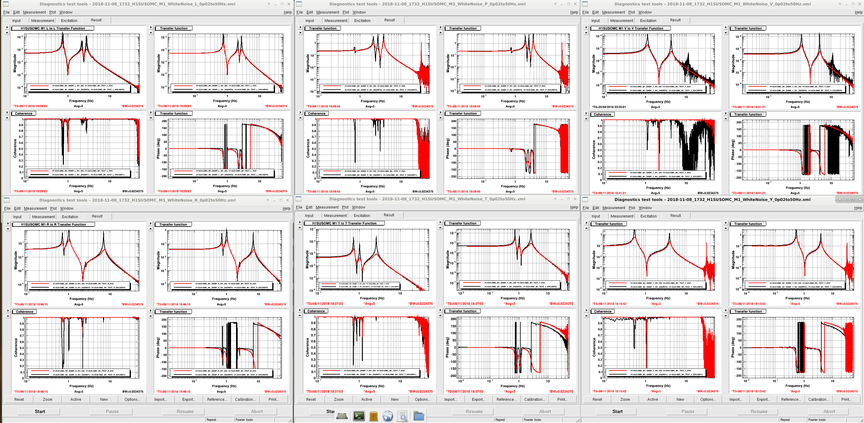
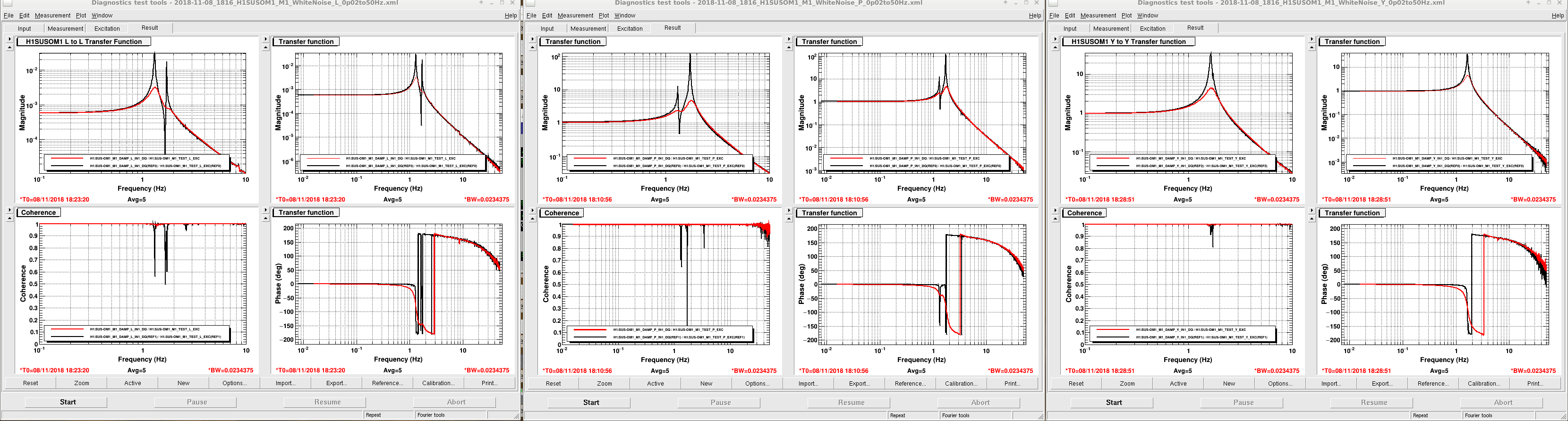
The data was taken this morning when the IFO was being prep for locking. All HAM6 related items were in healthy states (OPS overview was all green). No invasive activities going on in the LVEA. The references used for these plots could be more recent, I just pulled up the most recent template, ran it, and save-as to new date without changing the reference.
OMC reference trace date: 25/04/18
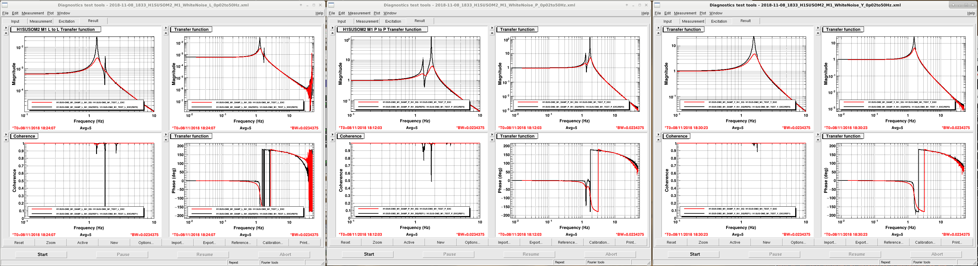
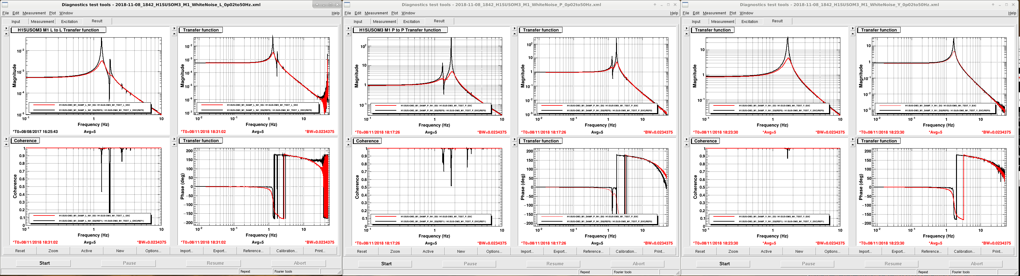
OM1, OM2, OM3 reference traces date: 08/08/17
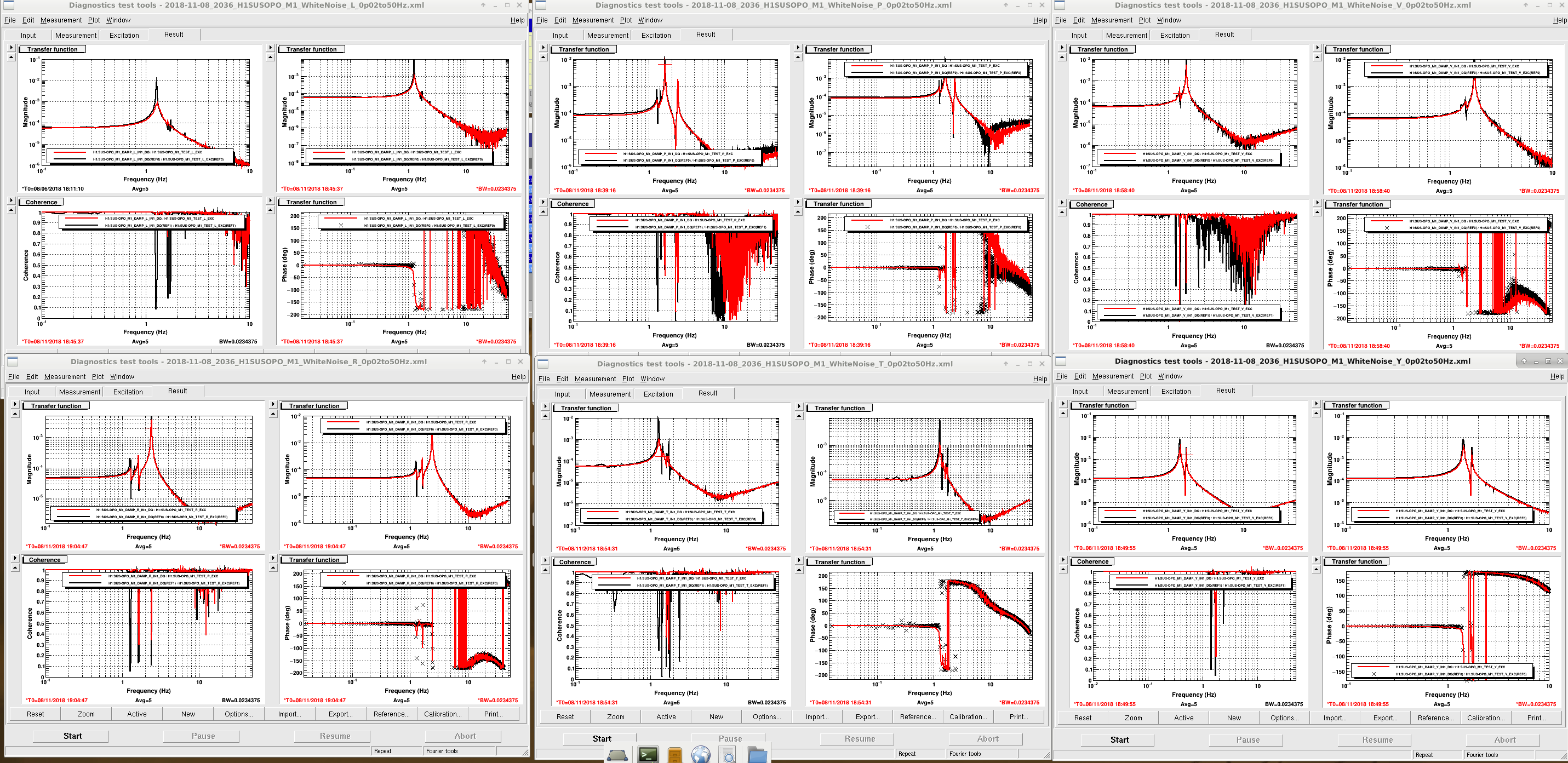
OPO reference trace date: 08/06/18
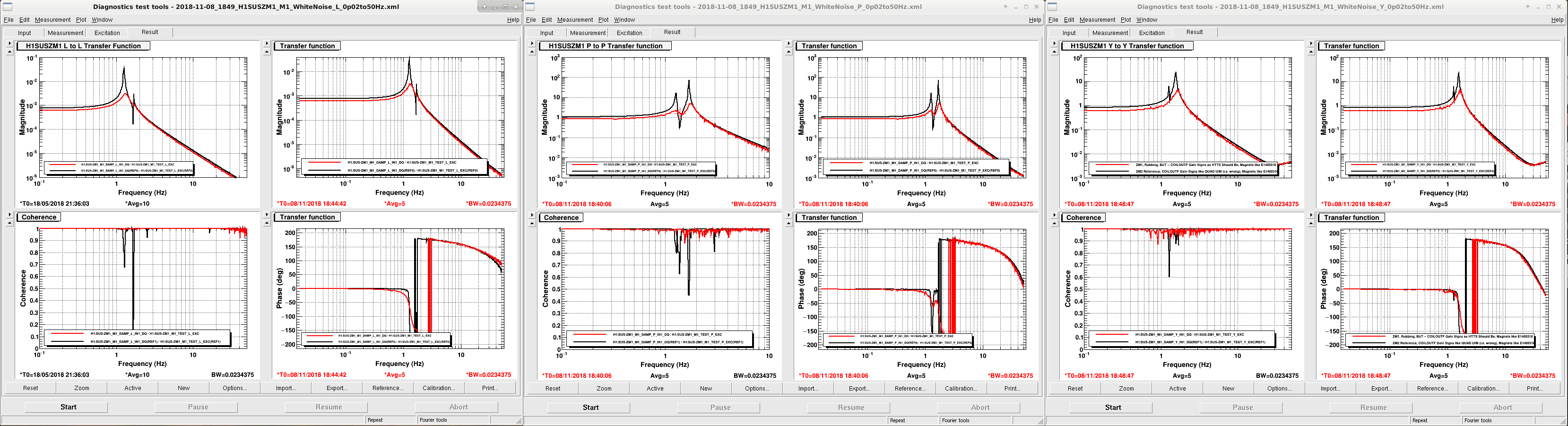
ZM1 reference trace date: 18/05/18
The files were saved in:
/ligo/svncommon/SusSVN/sus/trunk/OMCS/H1/OMC/SAGM1/Data/
/ligo/svncommon/SusSVN/sus/trunk/HTTS/H1/OM1/SAGM1/Data/
/ligo/svncommon/SusSVN/sus/trunk/HTTS/H1/OM2/SAGM1/Data/
/ligo/svncommon/SusSVN/sus/trunk/HTTS/H1/OM3/SAGM1/Data/
/ligo/svncommon/SusSVN/sus/trunk/OPOS/H1/OPO/SAGM1/Data/
/ligo/svncommon/SusSVN/sus/trunk/HTTS/H1/ZM1/SAGM1/Data/
Having trouble committing to svn at the moment, but will happen eventually.
Committed to svn.