Jenne, Peter, Hang
We noticed that the DARM noise around 20-30 Hz was not as ''smooth'' as our best references, indicating there were some scattering noises. As the first step, we shook the CPs similarly to what was done in LHO:37053 and then moved their alignments to minimizing the scattering shelves.
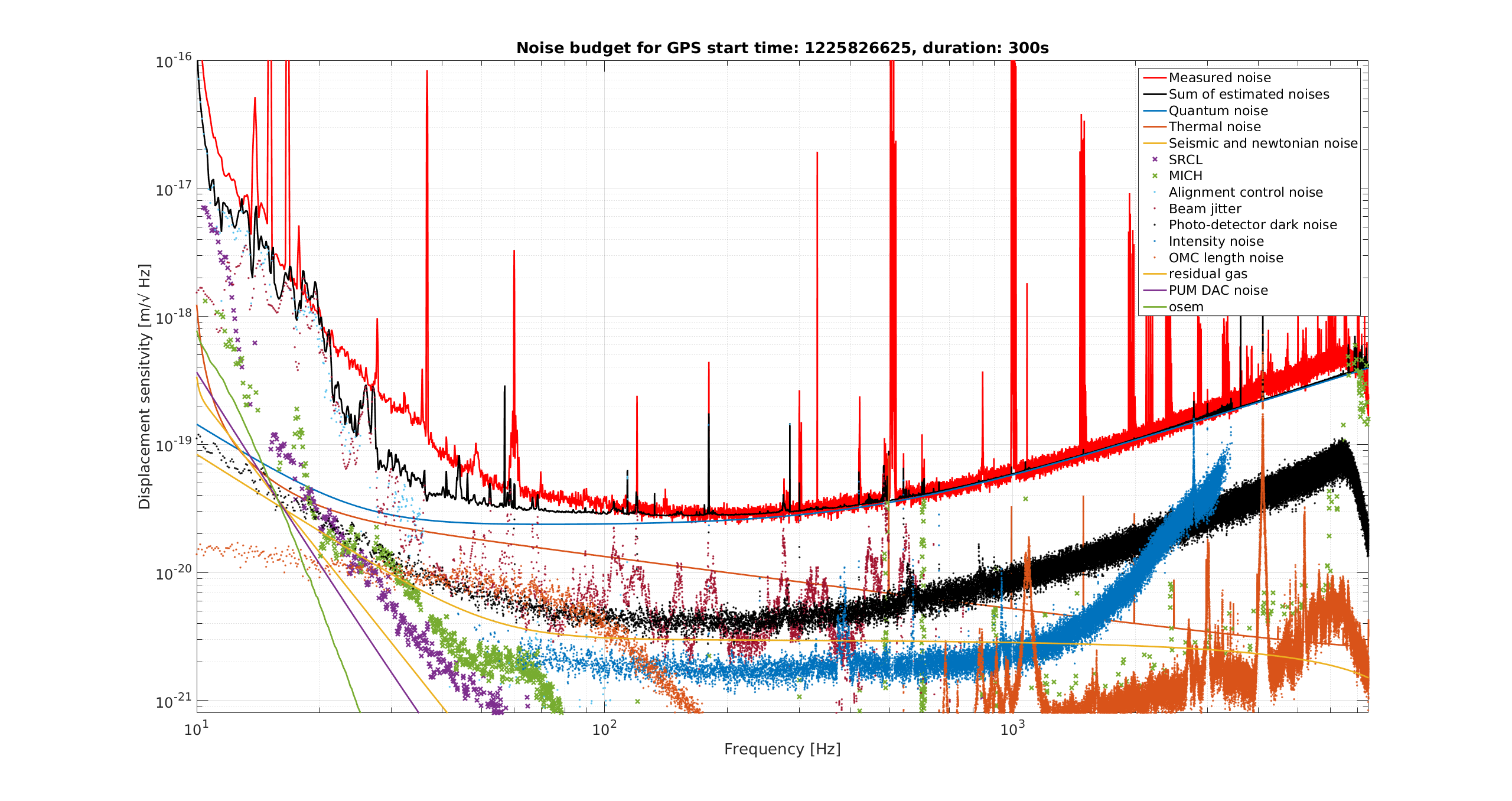
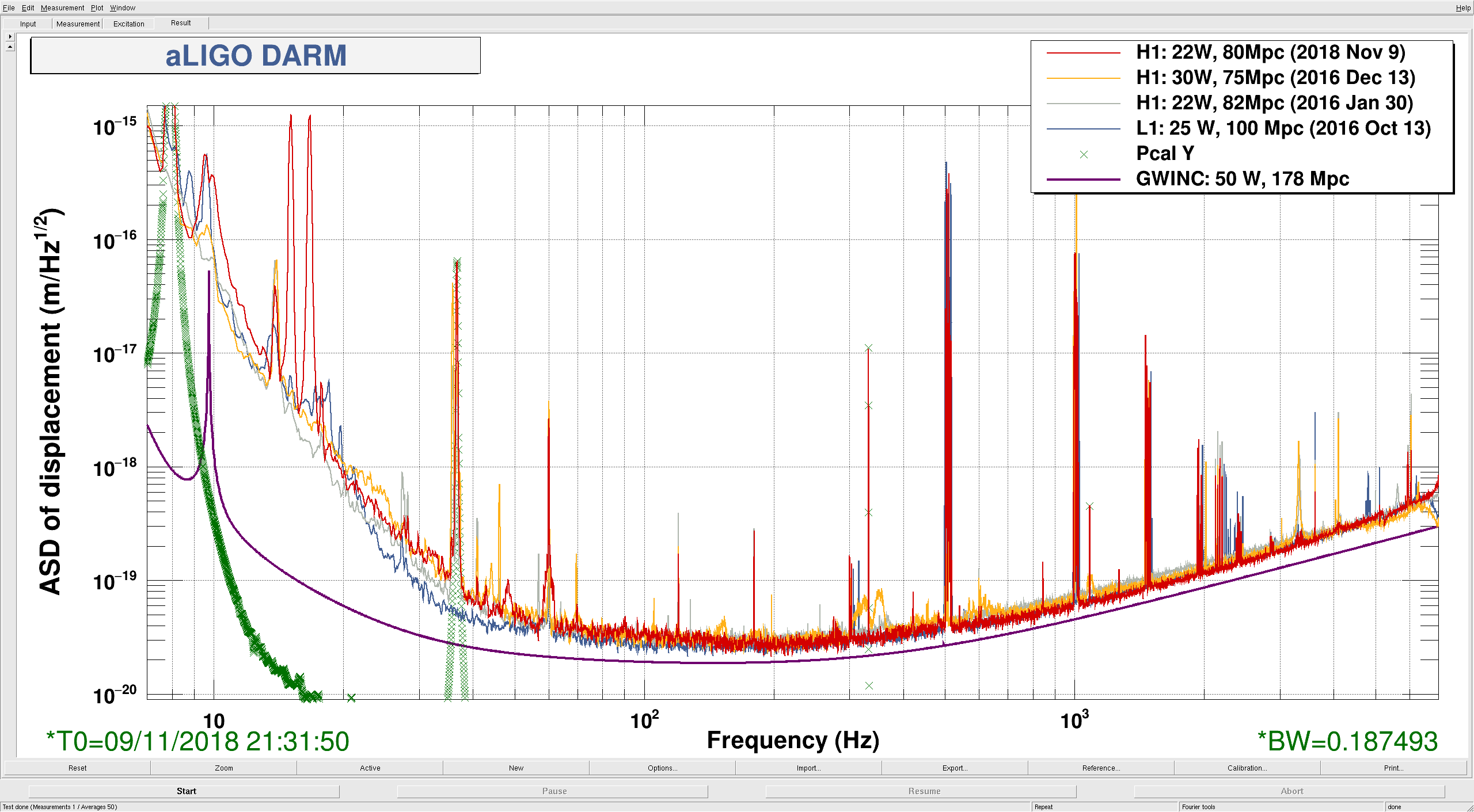
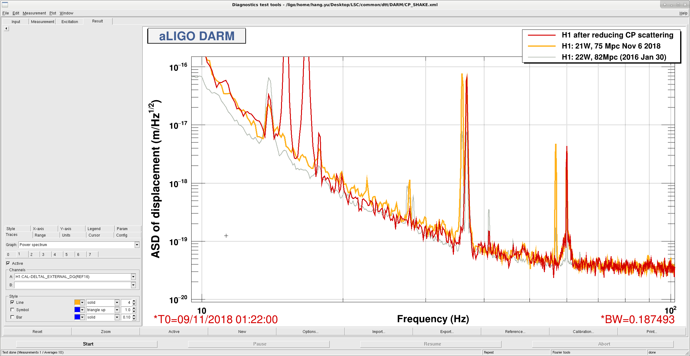
The CP moves led to a broadband improvement in DARM from ~15 Hz to ~ 40 Hz. Please see the first attached plot for a noise comparison (red: DARM after moving CP; orange: O3 best reference before the CP move; grey: old best).
==================================================================
Details
We dithered the CPs in length at 0.1 Hz with an amplitude of roughly 20 um (600 ct to SUS-ITMX/Y_R0_DAMP_L_EXC) to create significant scattering shelves in DARM. Then we moved the CPs in P/Y to minimize the shelves.
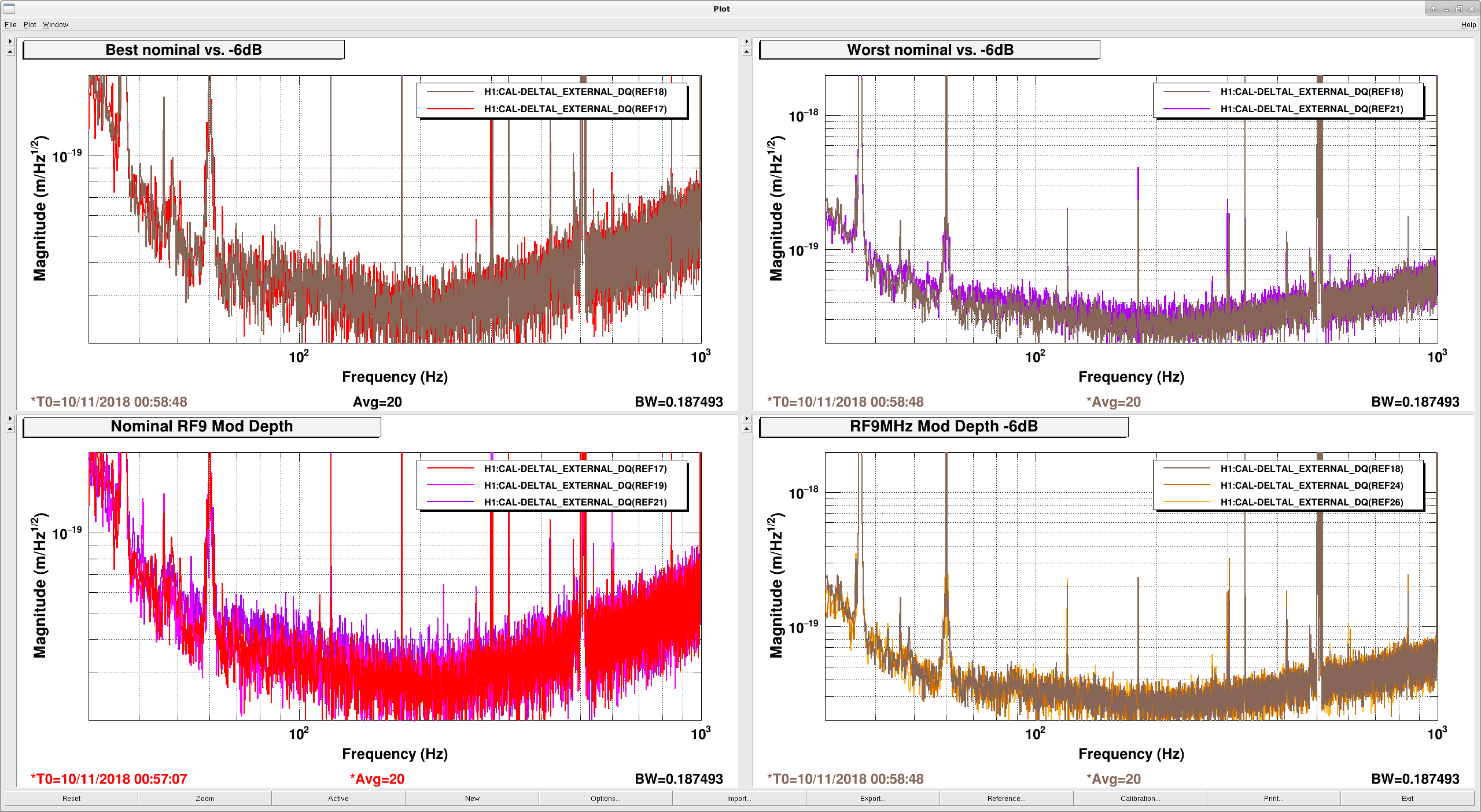
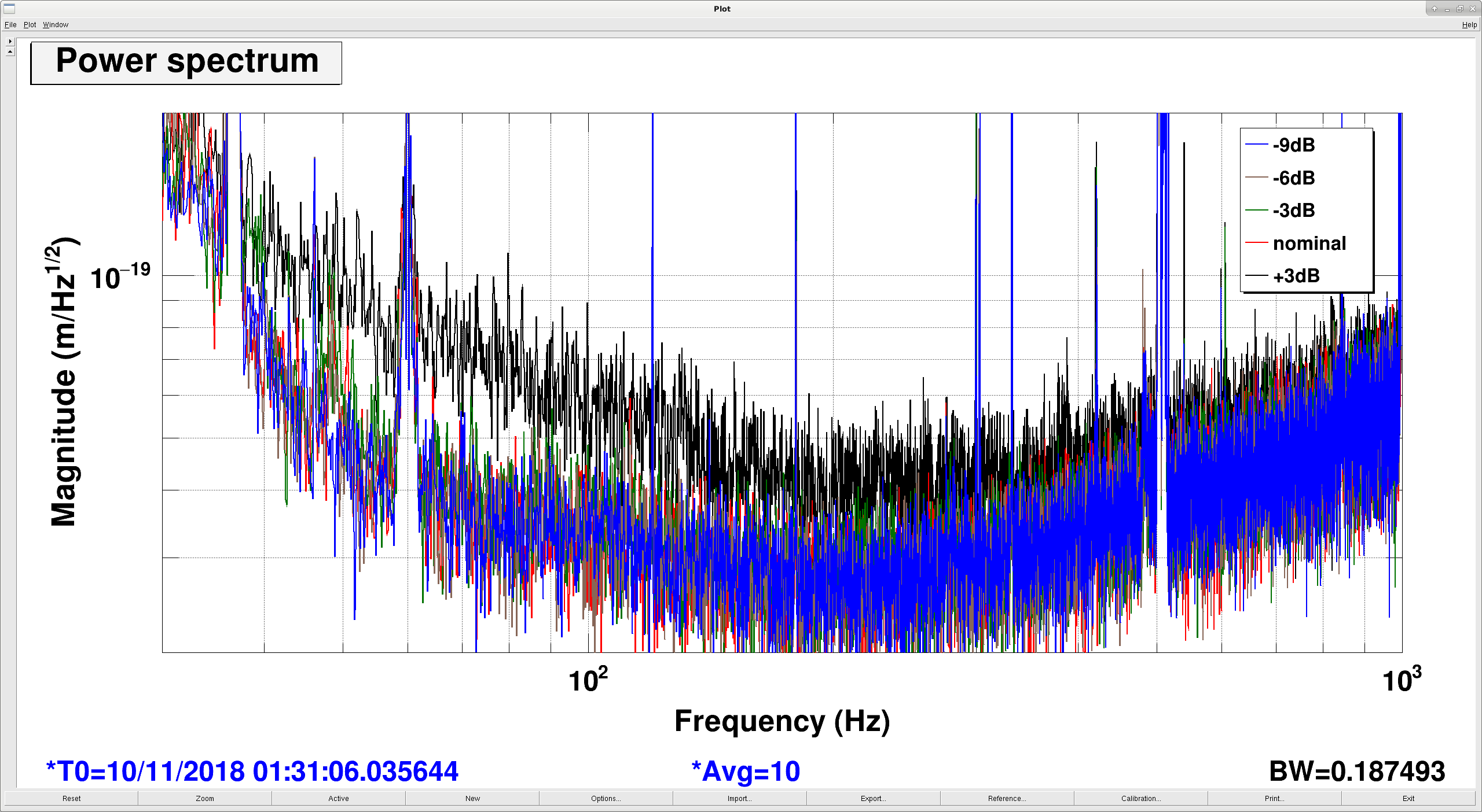
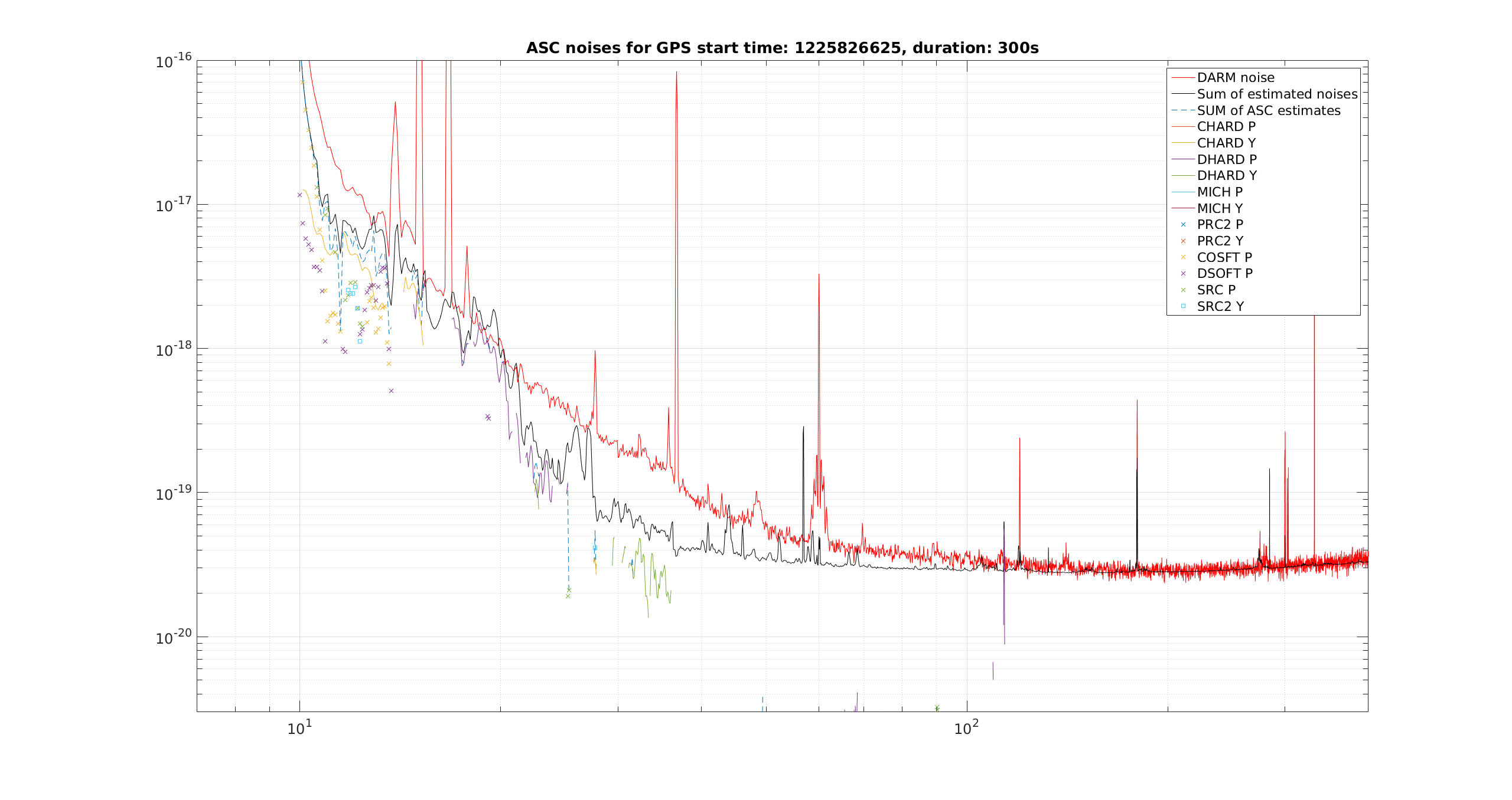
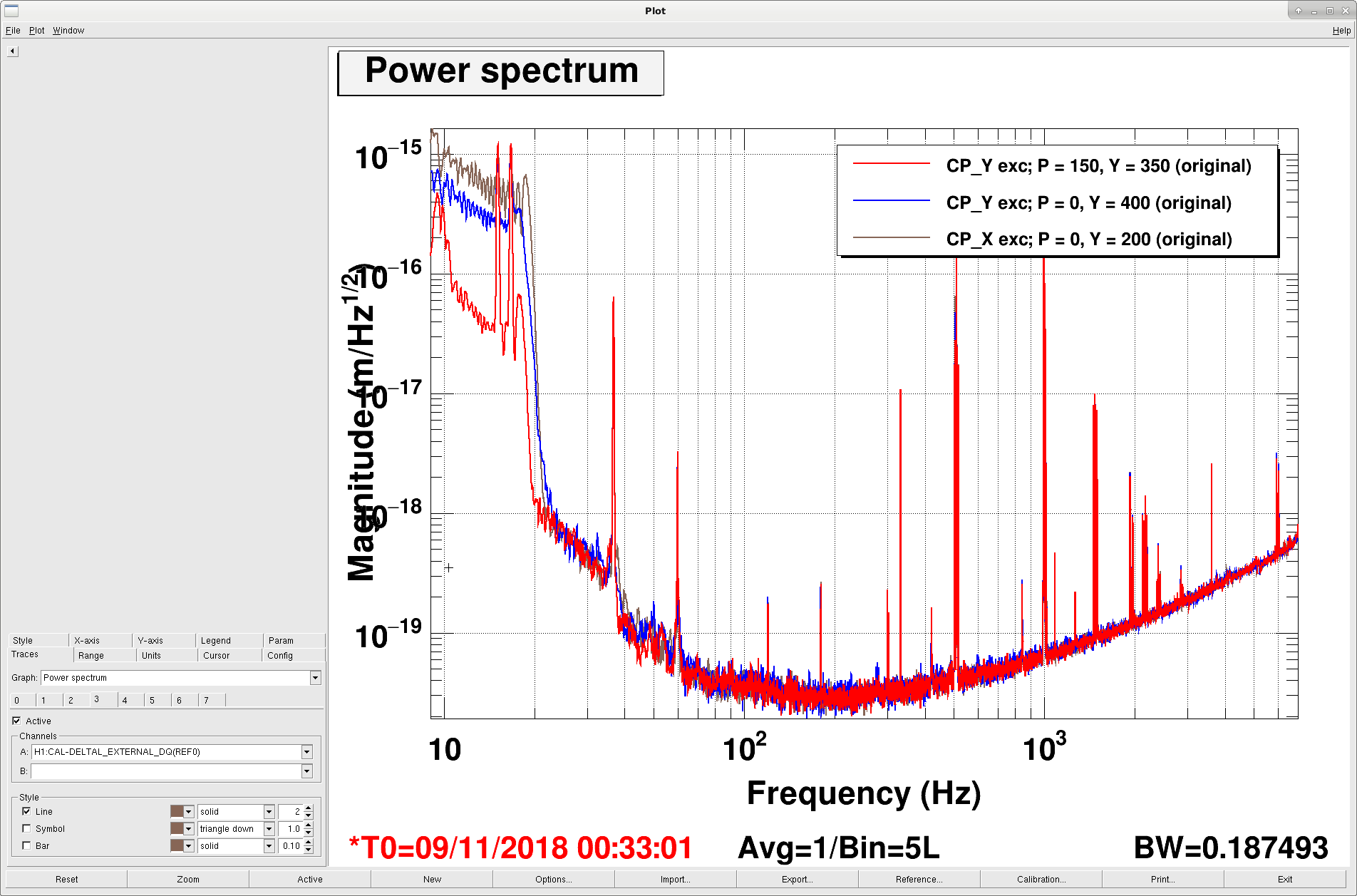
In the second plot we showed some examples of the scattering shelves. The blue/brown traces were shelves created when we excited CP_Y/X in length, respectively, with the CPs at their original alignments. For CP Y, we were able to reduce the scattering shelf by almost an order of magnitude by moving it in PIT +150 urad and in YAW -50 urad from its original position. For X, we tried to move it +- 100 urad in both P/Y yet the original one seemed to be optimal already.
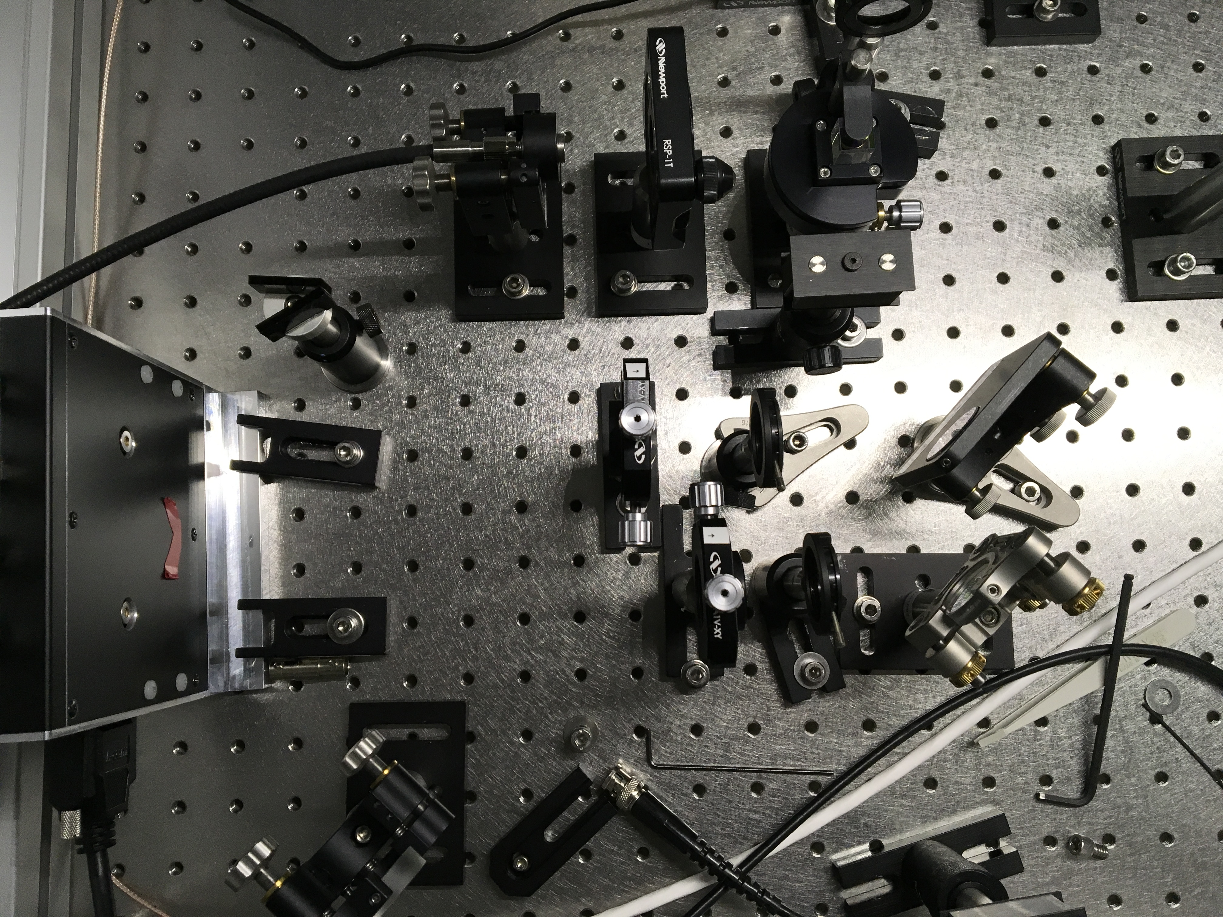
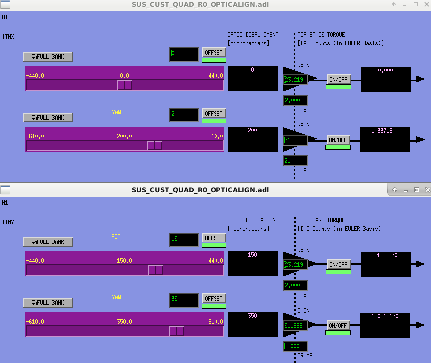
In the last plot we showed the current alignment of the CPs.
==================================================================
Since our DARM was still not as smooth as LLO, there might still be some scattering from BS AR or ITM ARs that might be worth doing further investigations.