sheila.dwyer@LIGO.ORG - posted 23:08, Monday 05 November 2018 (45036)
Summary alog
There have been a lot of things happening today, most of which is other logs, but I thought it would be useful to make a summary:
- DRMI locking:
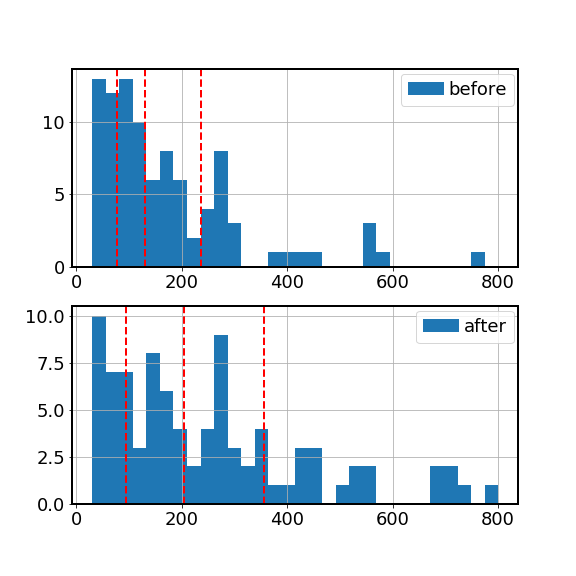
- This morning Hang undid the filter change that he made to the MICH low pass a month or so ago. Hang made the plot which is the first attachment and shows the lock acquisition times before and after he made his change. The vertical red lines show percentiles of the locking time.
- Beam dumps:
- After locking was recovered, Jenne and I added beam dumps for the beams transmitted by the AS AIR and POP AIR beam diverters 45010 More work is needed to dump the popair beam well.
- ASC cut offs:
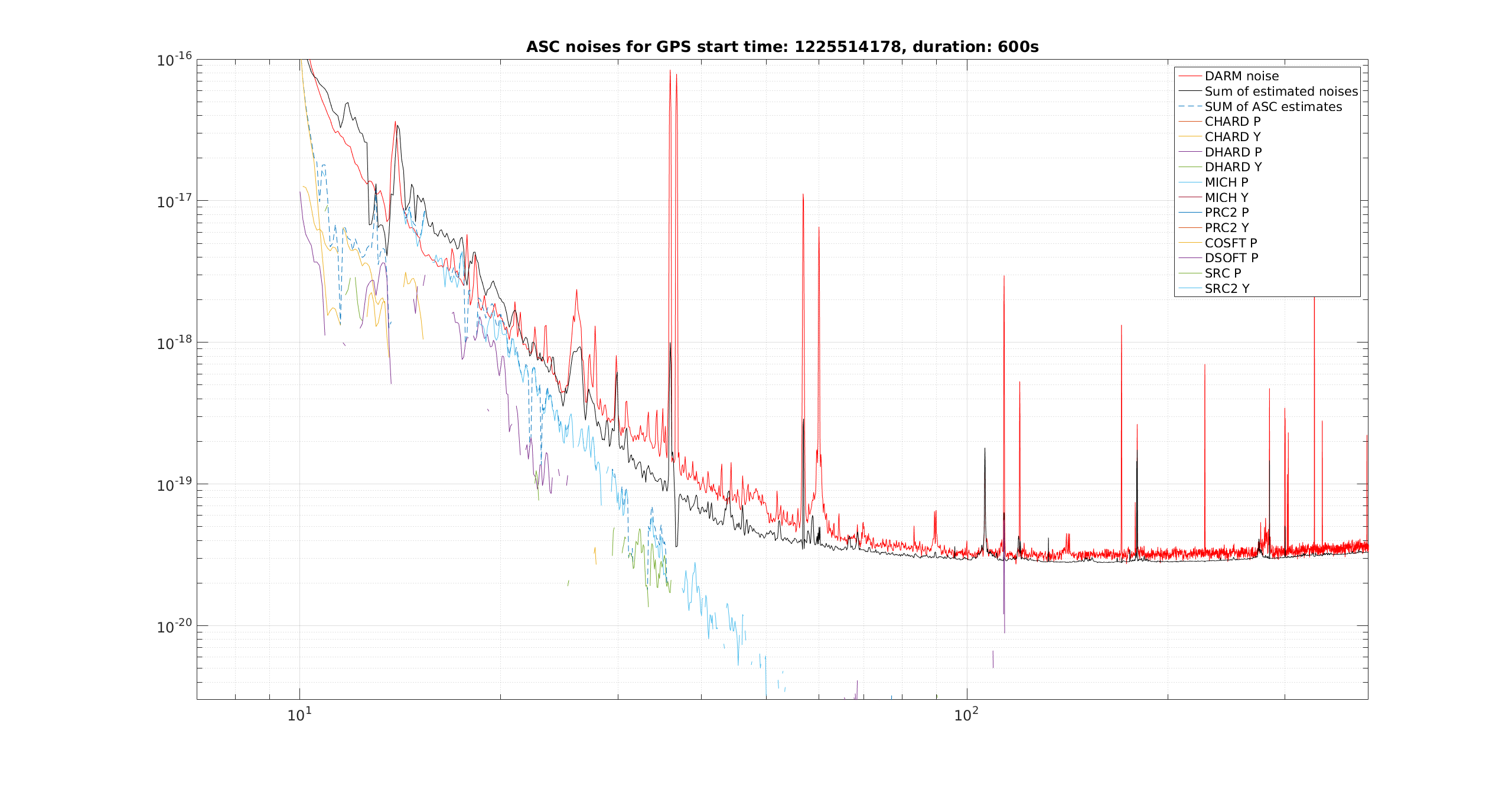
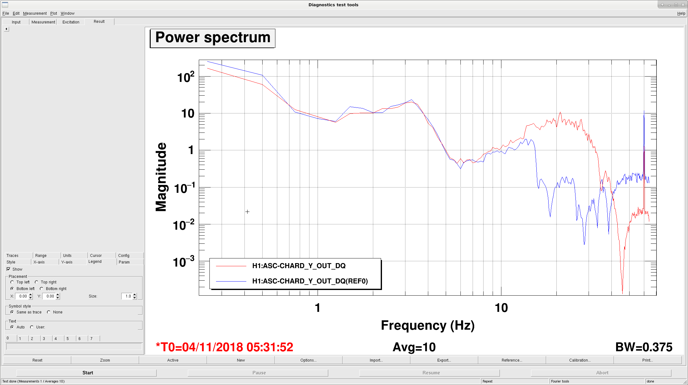
- I asked Hang to look at why CHARD Y noise was higher in our noise budget than it was in O2, he changed the low pass so that CHARD Y is now much lower in our noise budget 45023
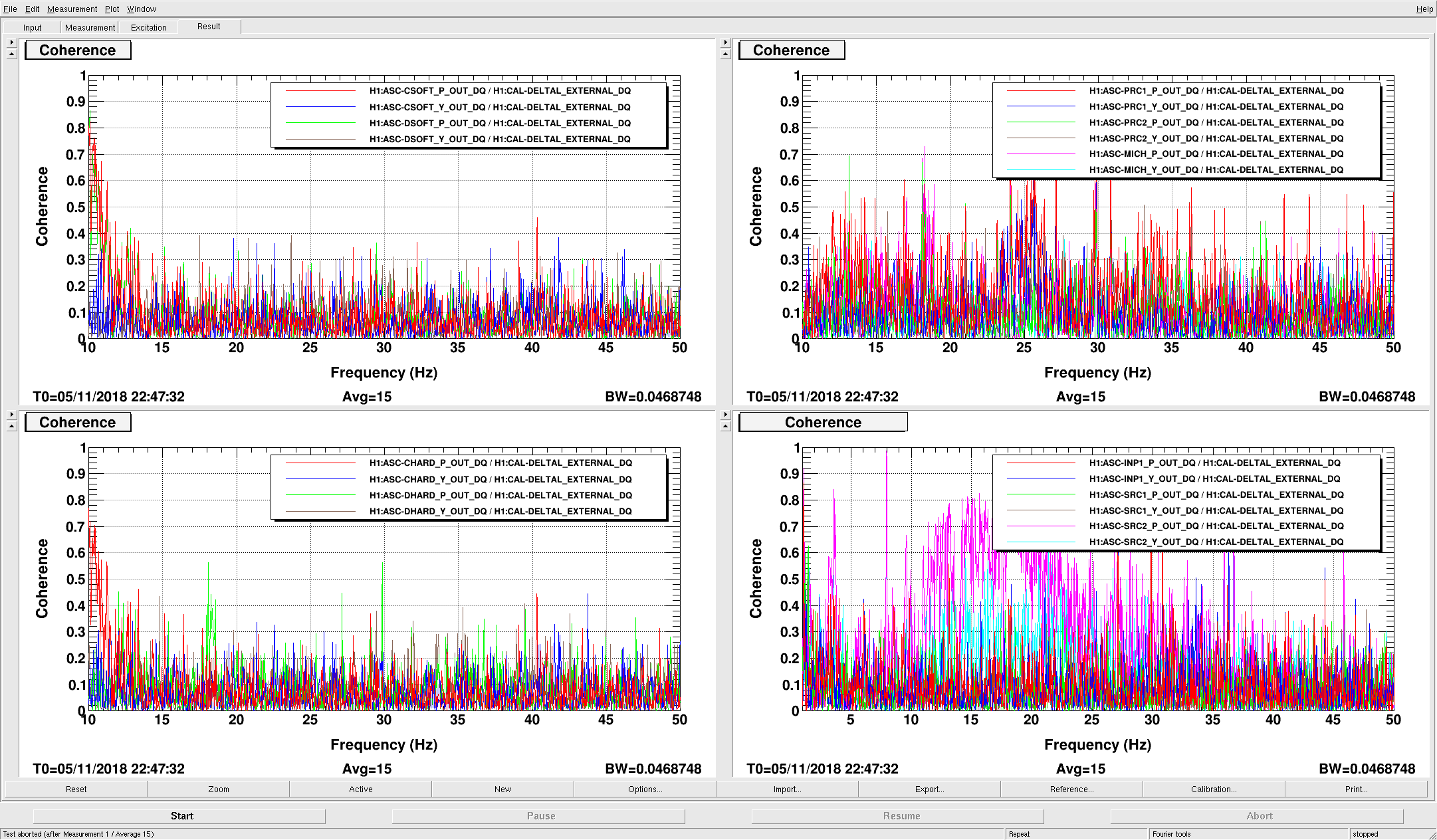
- Jenne noticed that SRC2 P had high coherence with DARM, and did noise injections. 45026 Like AHRD Y, this was a significant contribution the the DARM noise budget up to 30 Hz until Hang added roll offs 45032
- Hang also reduced the gain of SRC2Y and added a cut off there. This is only engaged in the LOW_NOISE_ASC state because it causes instabilities if used earlier.
- We took new noise budget injections for SRC2 P, Y, and CHARD Y after these changes were made.
- LSC noise:
- Stefan checked the input matrix element from POP9I to SRCL that is used to cancel the PRCL signal in POP45I. 45034 As we suspected, this coupling seems to be changing from lock to lock.
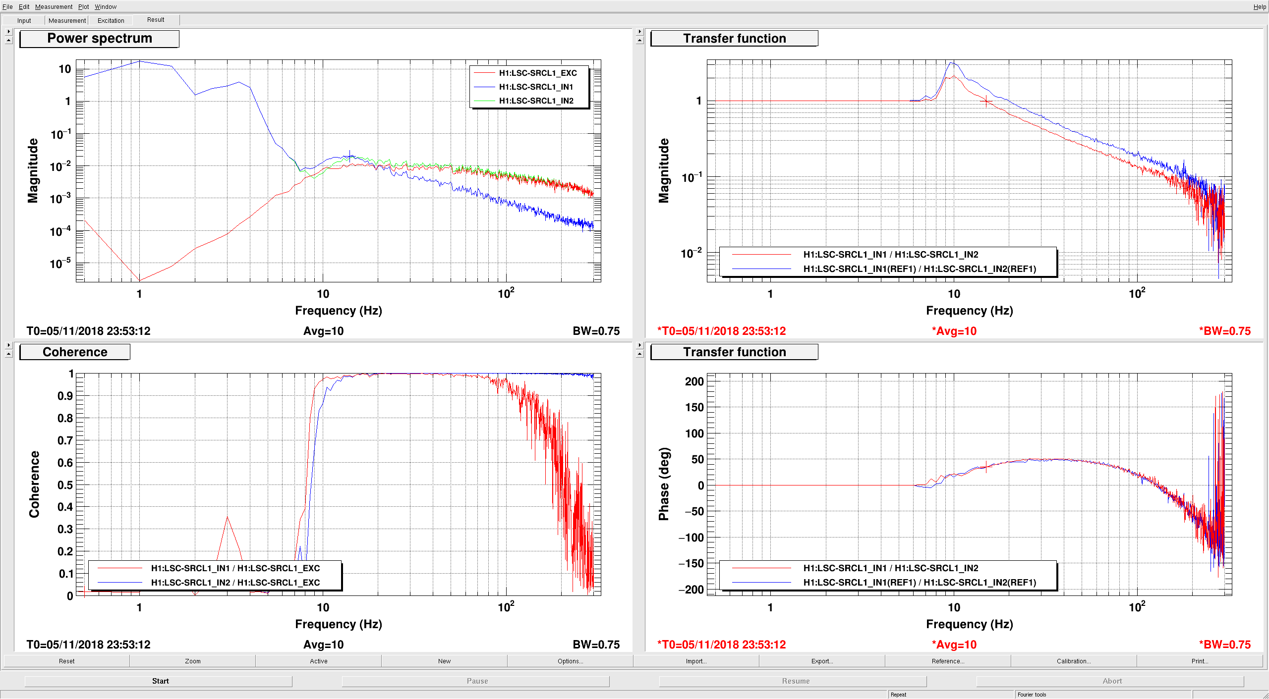
- Stefan also lowered the SRCL gain and put this in the guardian. 45035, then we redid the SRCL injection for the noise budget.
- We redid the SRCL and HAM3 noise injections for the noise budget after this work was done.
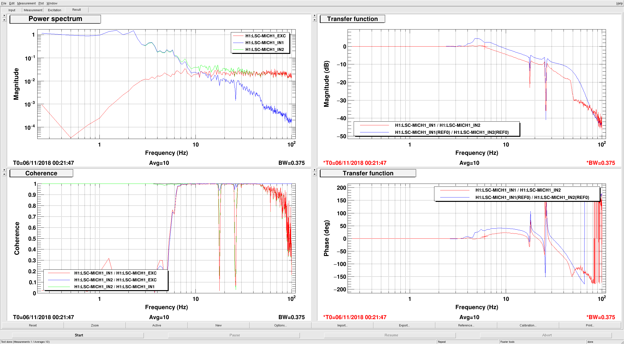
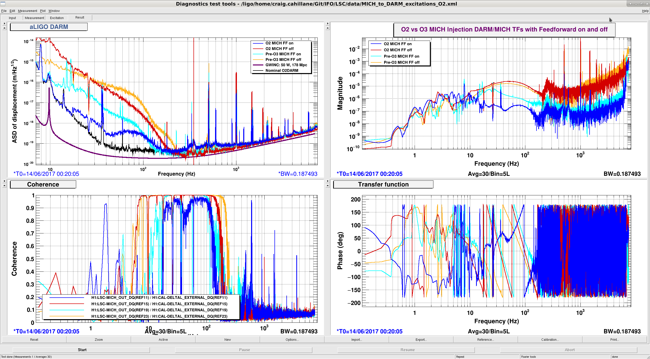
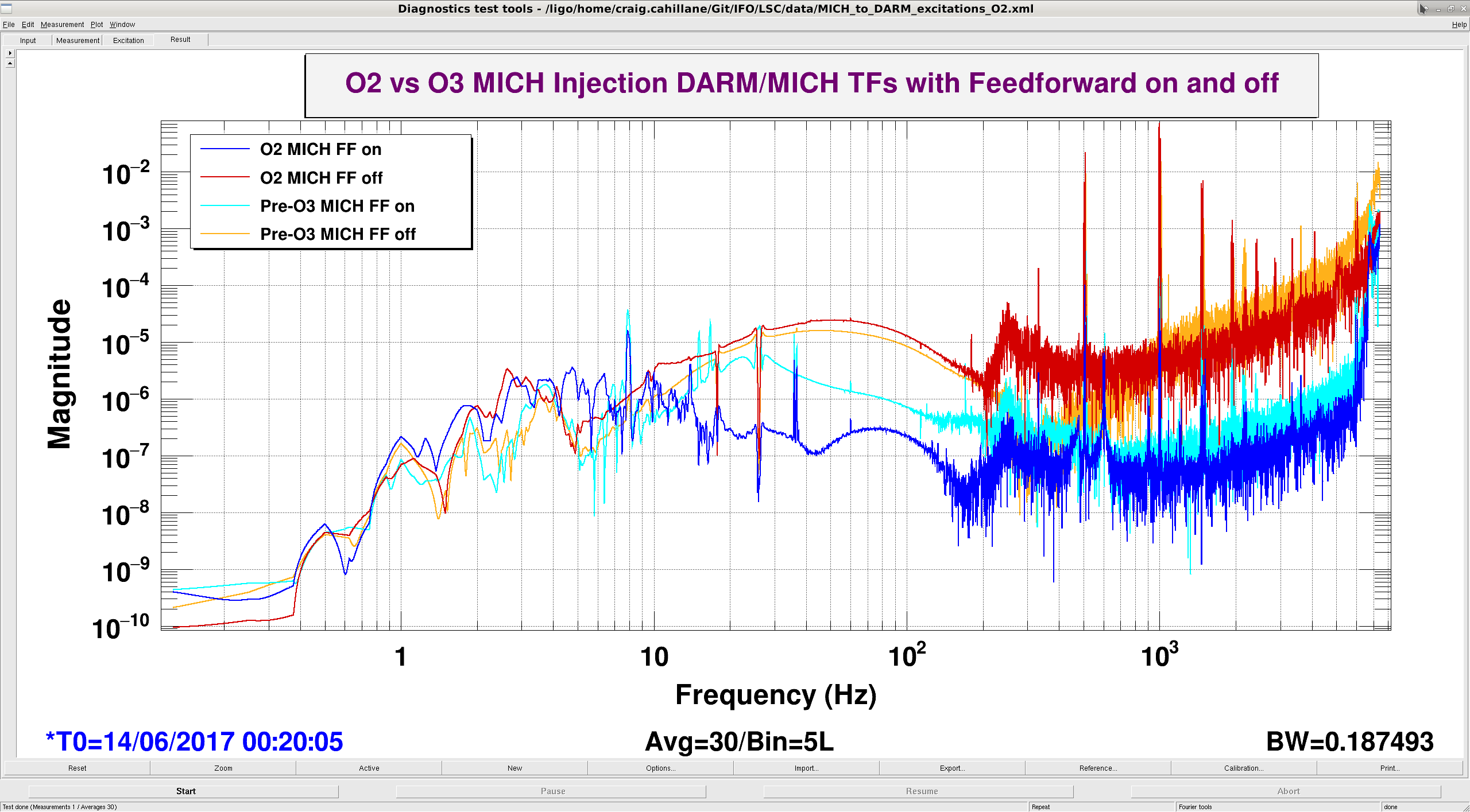
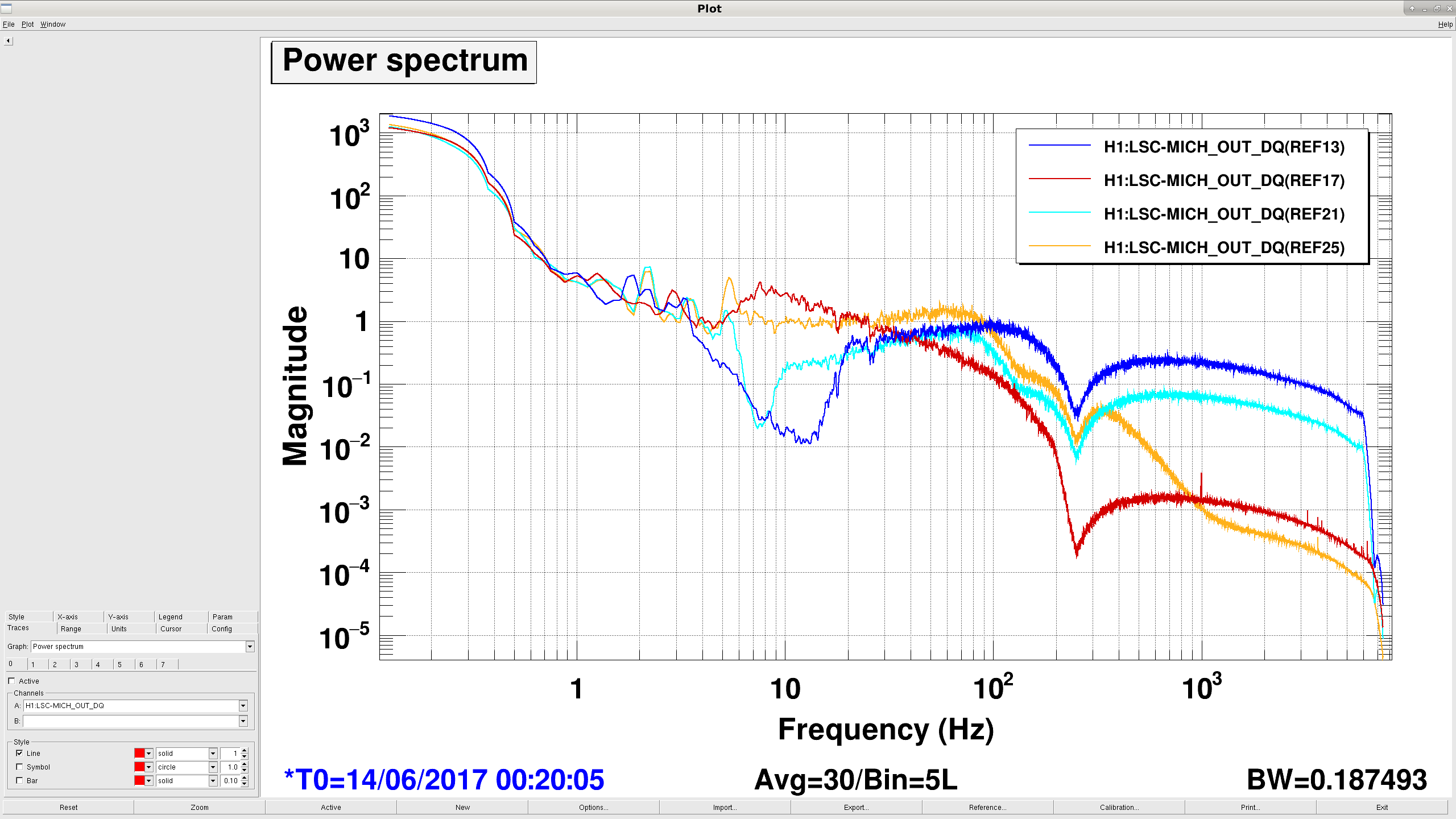
- Craig made a comparison of measurements Jenne and I had from O2 with ones he took recently of the MICH to DARM coupling with and without feedforward, 45029 the main message is that our coupling to DARM is the same but our feedforward performance has been worse.
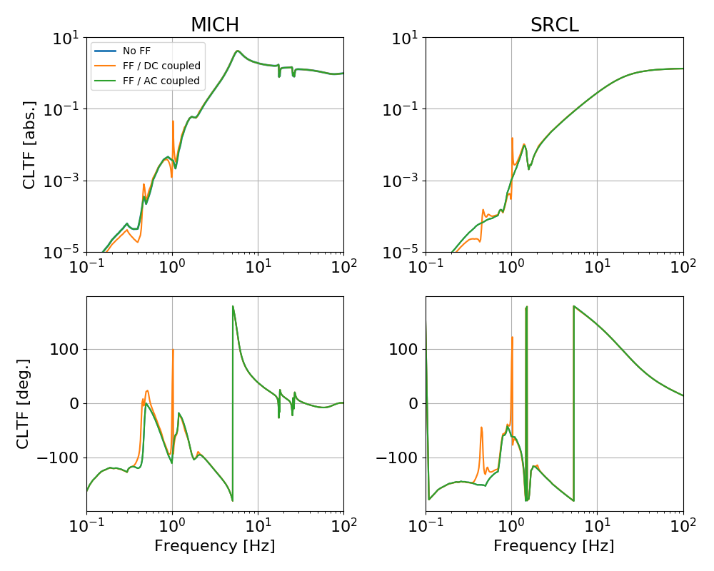
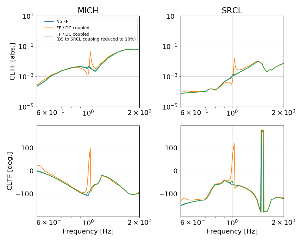
- Gabriele posted an interesting model of how the SRCL FF can be unstable, which is why we need to AC couple it which limits how accurate our feedforward can be. 45030
- We moved the notches for the beam splitter bound and roll modes into the LSC filter bank, rather than the suspension filter bank. This was to avoid having them in the feedforward path which makes fitting the feed forward more difficult. We set up the DRMI guardian to acquire with the notches still in the suspensions, so that there high Q filters can be after the triggering rather than before, then after DRMI has acquired we swtich it to the LSC bank. The real motivation for doing this is that I want to be conservative about changes to DRMI acquisition.
- Craig has measured and done fitting to retune the MICH feedforward, sending the feedforward to the DARM actuator rather than the ITMs. The first round resulted in a similar level of suppression as the existing feedforward,
so Craig is now doing a recursive fitting.Craig was able to reduce the coherence using a recursive fitting 45038
- Georgia found possible down conversion of violin damping 45037
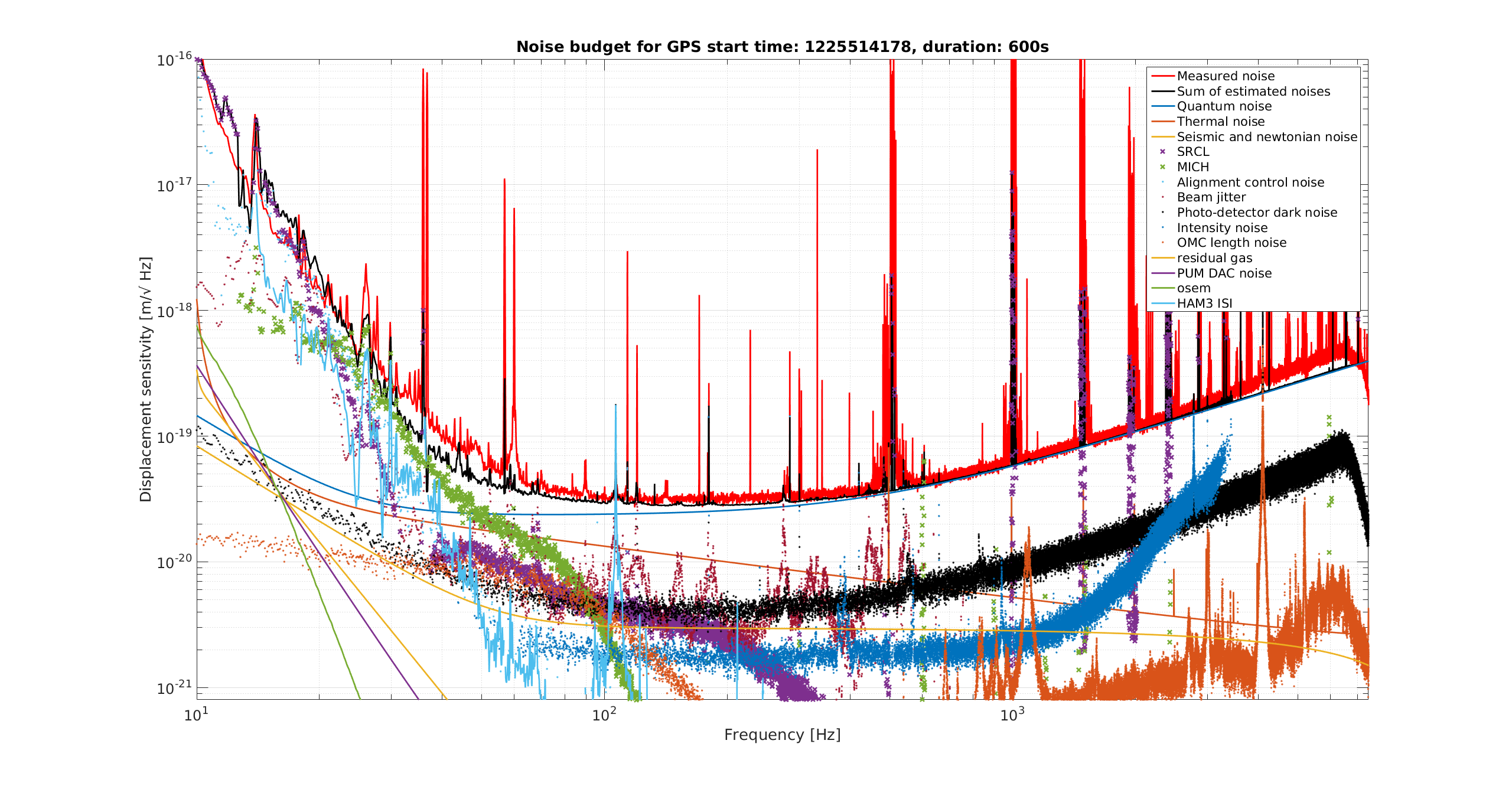
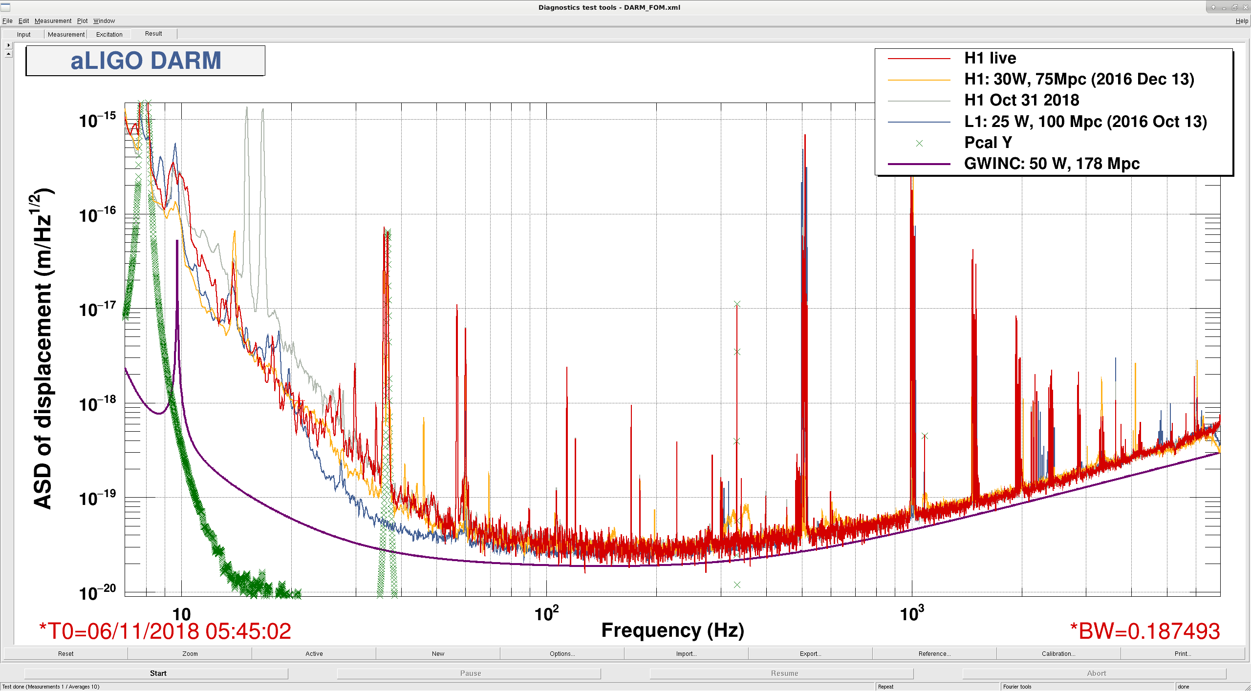
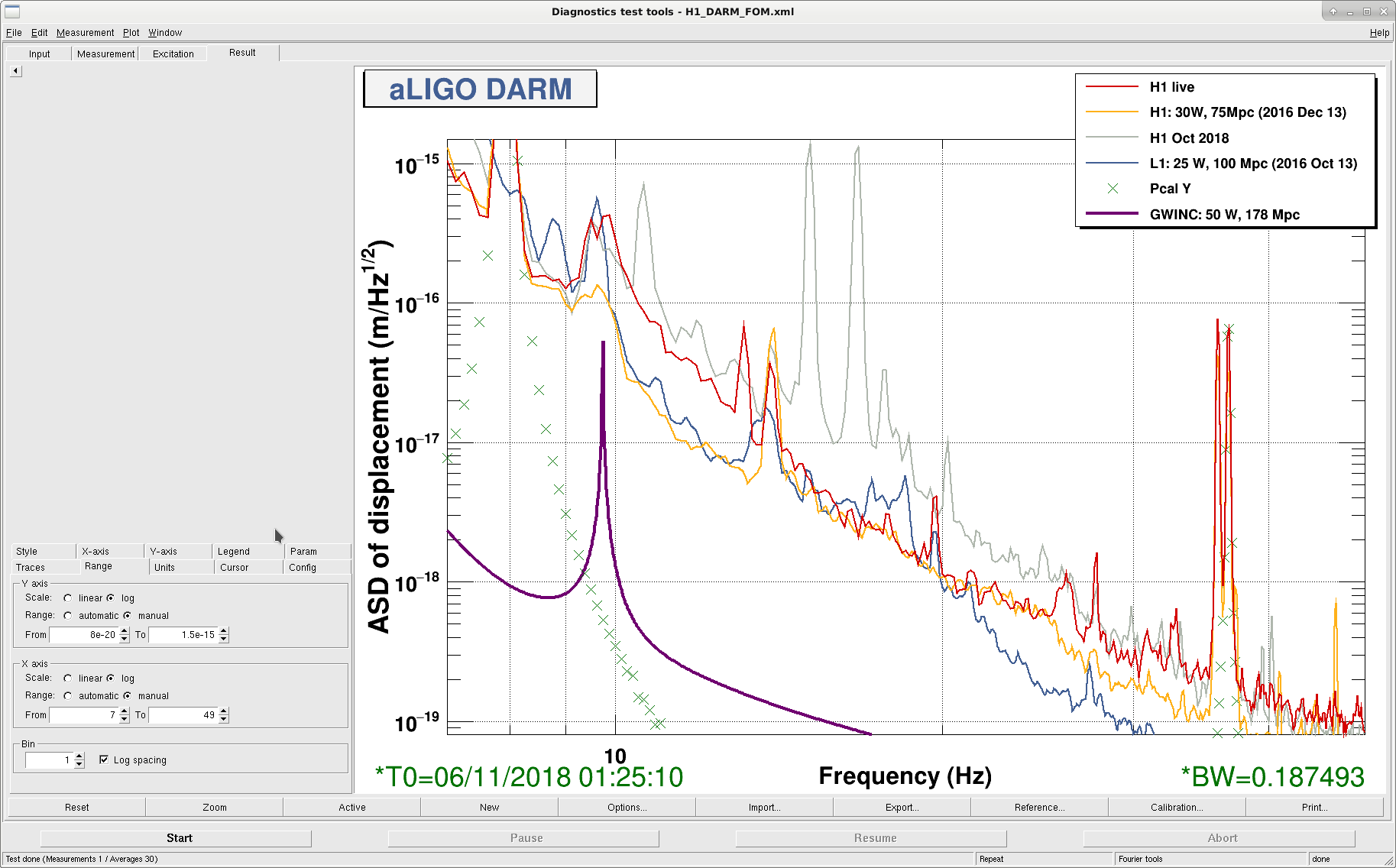
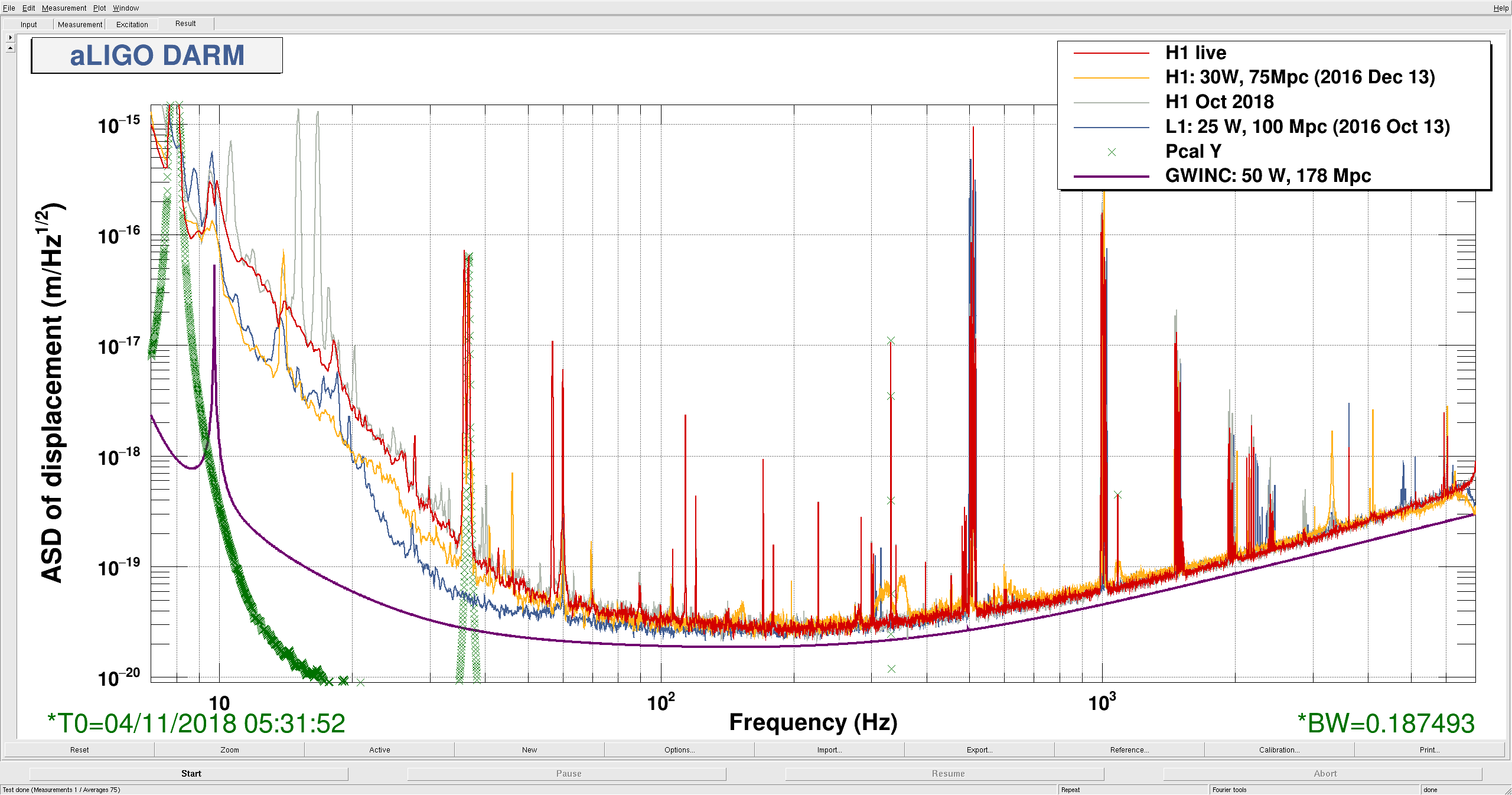
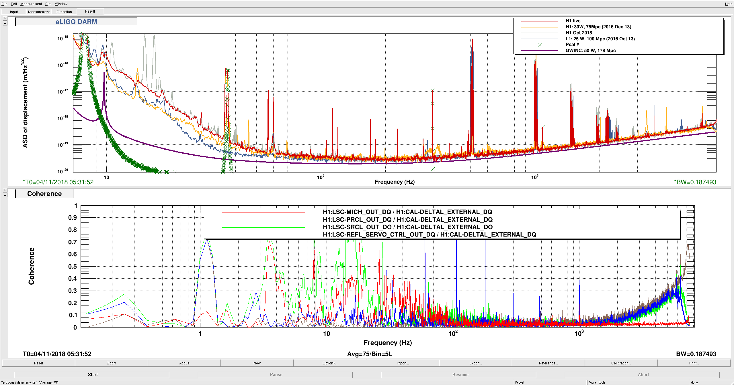
A noise budget including all of these improvements is attached, there is a trace here for HAM3 coupling as well as SRCL and MICH, but there is a risk that we are double counting now because the HAM3 noise couples to DARM through MICH (and SRCL). The last attachment is a comparison of the DARM spectrum tonight to Friday night in grey. The improvements today have brought us to the early O2 reference below 25 Hz.
Images attached to this report


