Displaying reports 44741-44760 of 88438.Go to page Start 2234 2235 2236 2237 2238 2239 2240 2241 2242 End
Reports until 19:09, Sunday 04 November 2018
H1 ISC
thomas.vo@LIGO.ORG - posted 19:09, Sunday 04 November 2018 (45009)
Trouble relocking after dolphin crashes

Dan Brown, Danny V., TVo

Note for the morning crew, after the frontend restarts from the dolphin crashing, we cleared all the affected watchdogs for SEI and SUS.  However, when we tried to relock, the green WFS wouldn't engage on both arms until we had to do some realignment and then WFS_PUM worked.  It seems like H1:LSC-TR_Y_NORM_MON has an elevated setting, maybe a dark offset somewhere that hasn't been reset?  Also, it seems like the IMC WFS are not engaging as well at first, but once I lowered the threshold on the ASC IMC trigger to 30 instead of 40, they resumed. 

I'm not sure what re-start procedure needs to happen in order to recover from such a dramatic front end bootfest, for now we're leaving the ISC LOCK guardian in down.

H1 CDS
thomas.vo@LIGO.ORG - posted 18:19, Sunday 04 November 2018 - last comment - 18:34, Sunday 04 November 2018(45006)
Dolphin crashed, manually restarting

Dave, Thomas, Danny, Jamie, Dan Brown

While attempting to re-lock the IFO, the dolphin network crashed and all the codes needed a restart.  we called Dave and he gave us instructions on how to log in and restart:

ssh controls@{computer}

then we run /etc/startWorld.sh

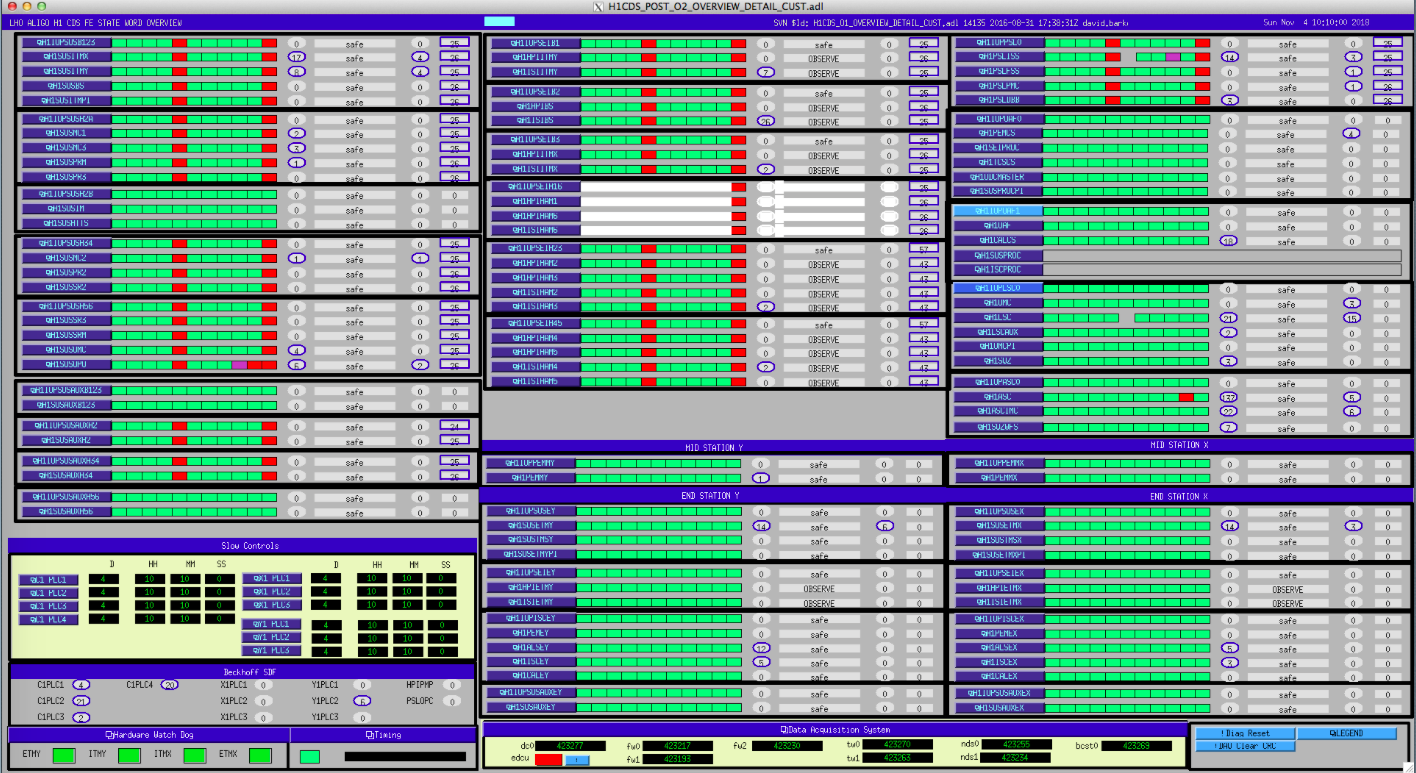
Everything is green on the cds overview screen now.

Images attached to this report
Comments related to this report
david.barker@LIGO.ORG - 18:27, Sunday 04 November 2018 (45007)

I've opened FRS11750 for this crash. We will fill in the lost-time after the IFO has been recovered.

david.barker@LIGO.ORG - 18:34, Sunday 04 November 2018 (45008)

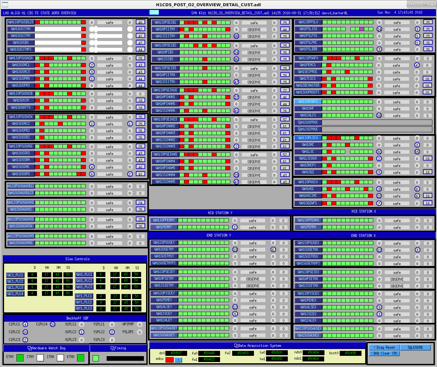
Looking at the CDS overview posted in the alog (taken soon after the crash while h1susb123 was being recovered), there are several things to note:

h1sush34 may have been OK, only timing errors not FEC errors.

h1seib3 looks like it was OK, only IPC errors.

h1seib2 has both IPC and IOP-DAC errors, which eventually required a restart to clear.

h1oaf1 looks perfectly OK, which is surprising since one would expect at least IPC errors.

During the recovery h1ioplsc0 was restarted, and Thomas reported that h1oaf1 did not show any errors when this was done (this is a slave to the h1lsc0 timing master). This sounds suspicious and I would be wary of h1oaf1's state.

H1 CDS (DAQ)
david.barker@LIGO.ORG - posted 10:25, Sunday 04 November 2018 - last comment - 12:52, Sunday 04 November 2018(45001)
h1seih16 kernel panic again, this time with associated DAQ data disruption

Looks like h1seih16 has had another kernel-panic event. This time it has caused the DAQ data for related front ends to become marked as bad (CDS overview attached).

Similarly to earlier crashes like this, nearly but not all of the front end computers sharing the same 10GE port on the DAQ data concentrator has bad DAQ data. In this case h1seih16 shares its h1dc0 port with psl, all corner station sus and seismic, and corner station sus-aux (except susauxb123). So it is not known why sush2b and susauxh56 are OK.

At this point there is no reason to think that the real-time models are not running correctly, we have just lost EPICS controls of h1seih16 and the DAQ data from those affected systems.

Would the first person to arrive on site please call me and we can recover the systems.

Images attached to this report
Comments related to this report
david.barker@LIGO.ORG - 10:35, Sunday 04 November 2018 (45003)

opened ticket FRS11749

david.barker@LIGO.ORG - 12:30, Sunday 04 November 2018 (45004)

Thomas, Dave:

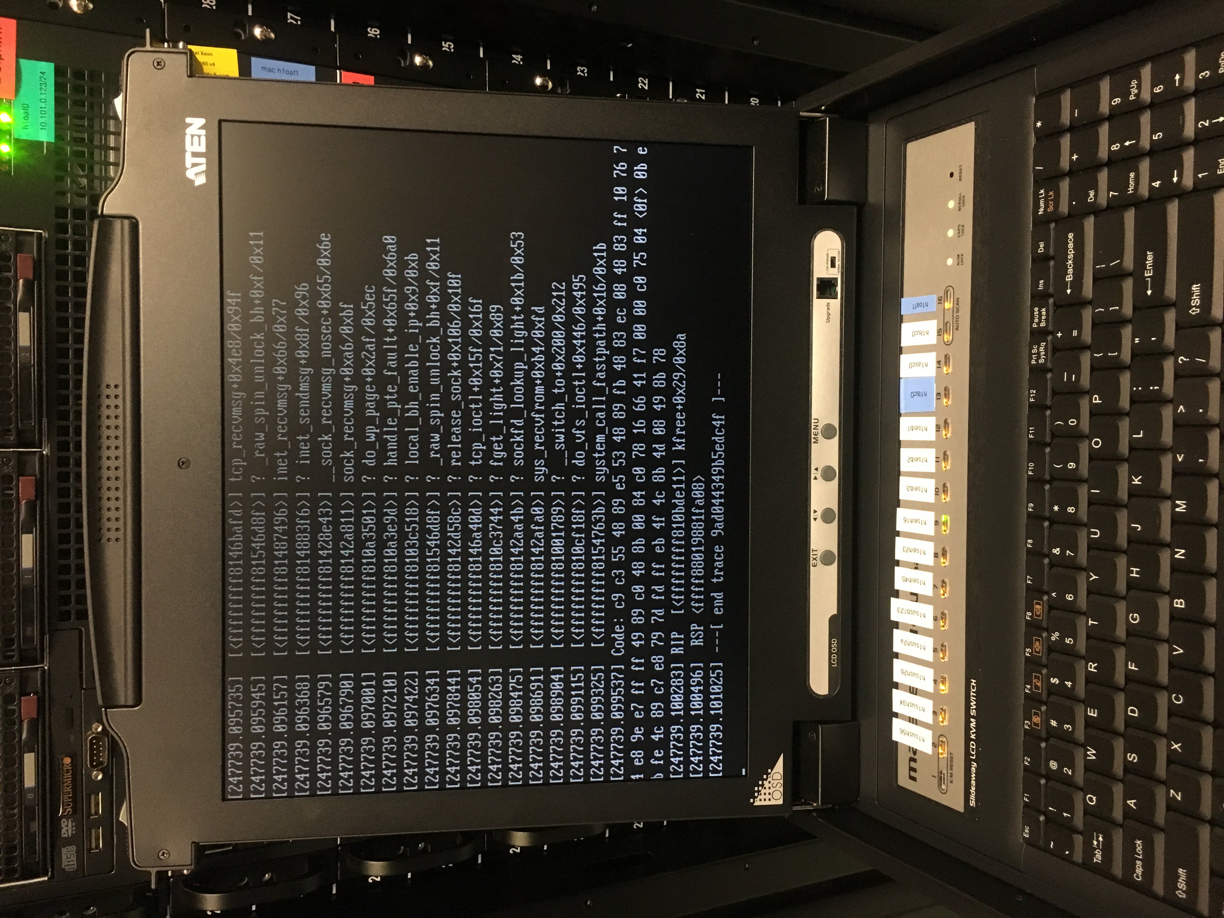
we recovered the system from the crash at 11:30 PST. Thomas took a photograph of h1seih16's console (attached), I disabled the dolphin switch port remotely (testing my new scripts in the process) and then Thomas pressed the front panel RESET switch. When h1seih16's mx_stream started, the bad-DAQ status on all the other front ends automatically cleared (no restart_streamers were needed). 

Images attached to this comment
thomas.vo@LIGO.ORG - 12:52, Sunday 04 November 2018 (45005)

We were able to relock to nominal low noise as well so the situation seems to be ok for now.

H1 ISC (ISC)
craig.cahillane@LIGO.ORG - posted 03:58, Sunday 04 November 2018 - last comment - 10:26, Sunday 04 November 2018(45000)
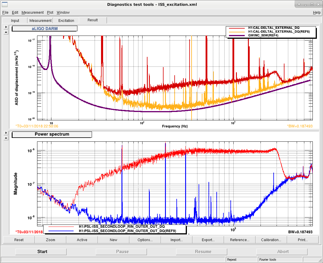
Injections Tonight
Frequency noise injections
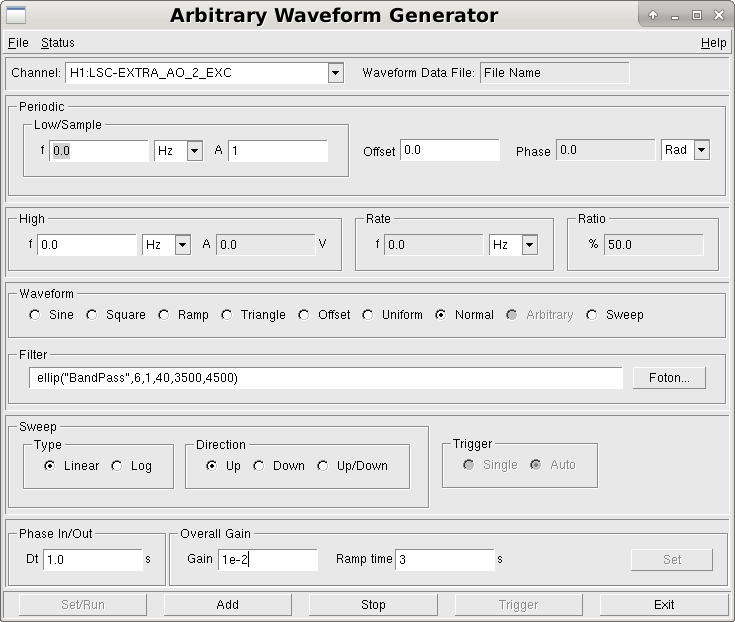
Into CARM Servo Board EXC A via LSC-EXTRA_AO_2_EXC (Pic 1)

Inj Amp     Start Time     End Time
-------------------------------------
1e-2        1225337909     1225338605
3e-2        1225338652     1225340457
3e-3        1225340607     1225341956
1e-3        1225341989     1225344477


Intensity noise injections
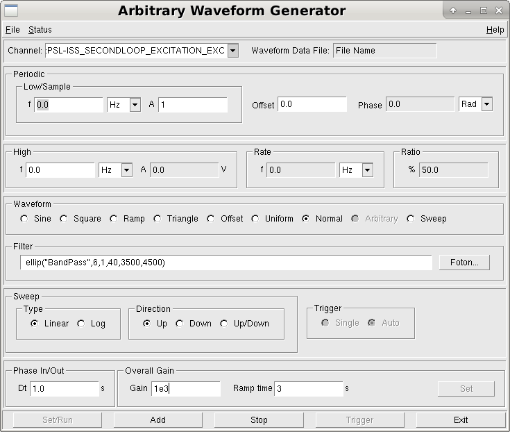
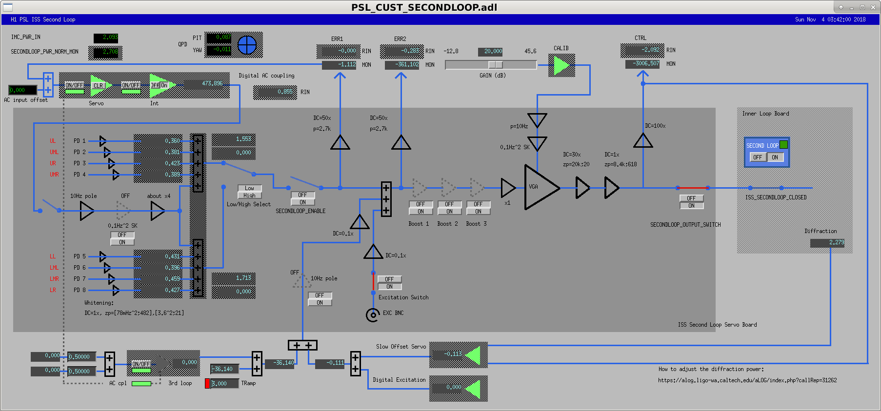
Into PSL-ISS_SECONDLOOP_EXCITATION_EXC with the low pass disengaged

Inj Amp     Start Time     End Time
-------------------------------------
1e3         1225346150     1225347492
3e3         1225347687     1225348986
1e4         1225349022     1225350095
3e2         1225350140     1225351784
1e2         1225351821     1225353267


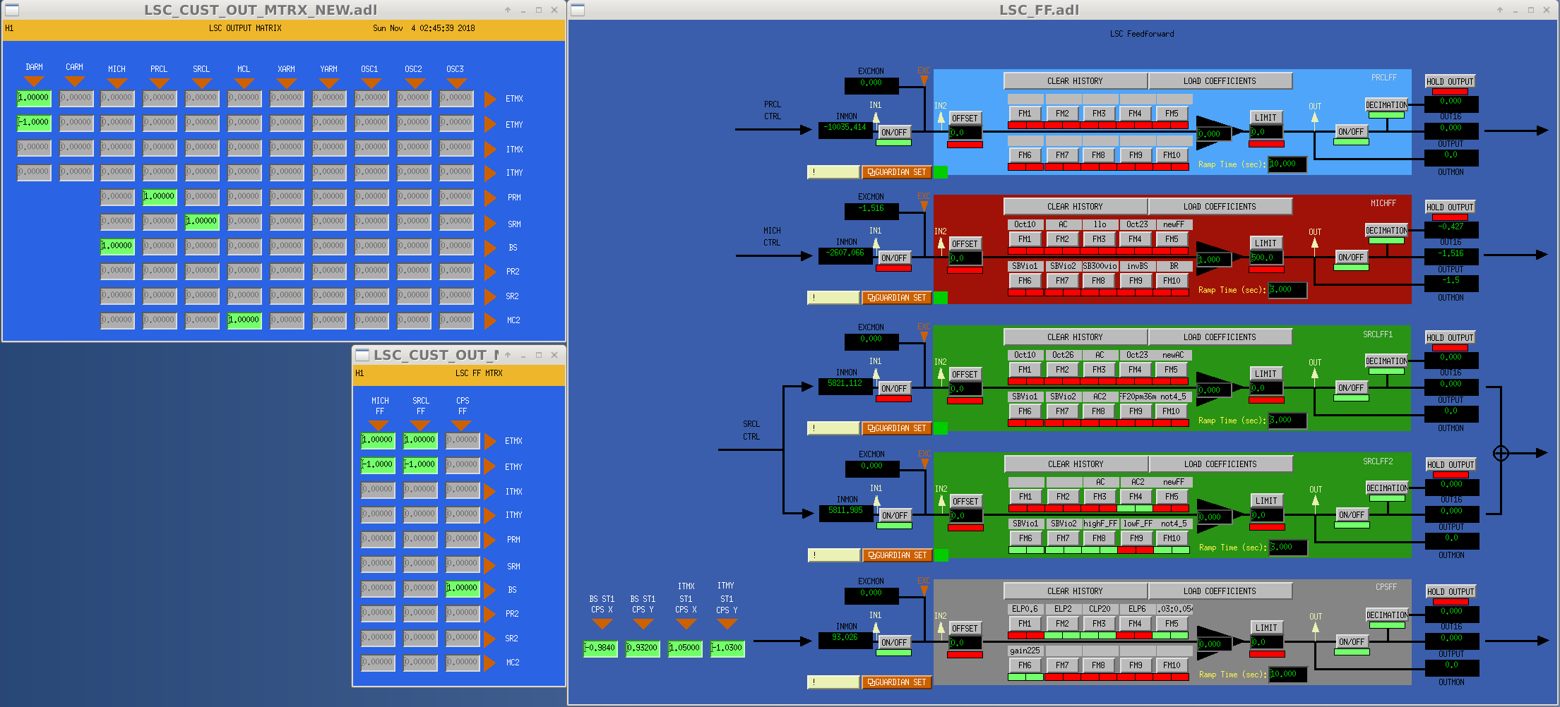
MICH Feedforward
I changed the actuators for the MICH FF to DARM measurements from the ITMs to the ETMs per Sheila's suggestion.
I did not have permissions to write to /opt/rtcds/userapps/release/lsc/h1/templates/, so I created two new templates in /opt/rtcds/userapps/release/lsc/h1/scripts/feedforward.
Have not had a chance to fit the MICH FF because I unlocked the IFO during the test.  

That is the only reason we lost lock this evening, had 13 straight hours of IFO time.  

I also altered ALS guardian so that X arm green WFS don't come on.  Mediocre alignment makes the WFS cause locklosses during LOCKING_ALS.
Images attached to this report
Comments related to this report
sheila.dwyer@LIGO.ORG - 10:26, Sunday 04 November 2018 (45002)

I forgot to log this yesterday, but I noticed that the X arm WFS have been set to off using the gain slider, so that they have not been on during initial alignment unless someone notices and turns them on.  This is probably the reason why we ended up with bad alignments after several inital alignment attempts during the day Friday, so I added a line that turns the WFS gain on in the ENABLE_WFS state.  

I think that we should still be able to turn off the X arm WFS by hand if needed.  It is likely that turning the X arm WFS off in the guardian is also turning off the Y arm WFS, which do work.  We should look into why the X arm WFS don't work anymore.  

H1 ISC
sheila.dwyer@LIGO.ORG - posted 18:19, Saturday 03 November 2018 (44998)
noise budget update

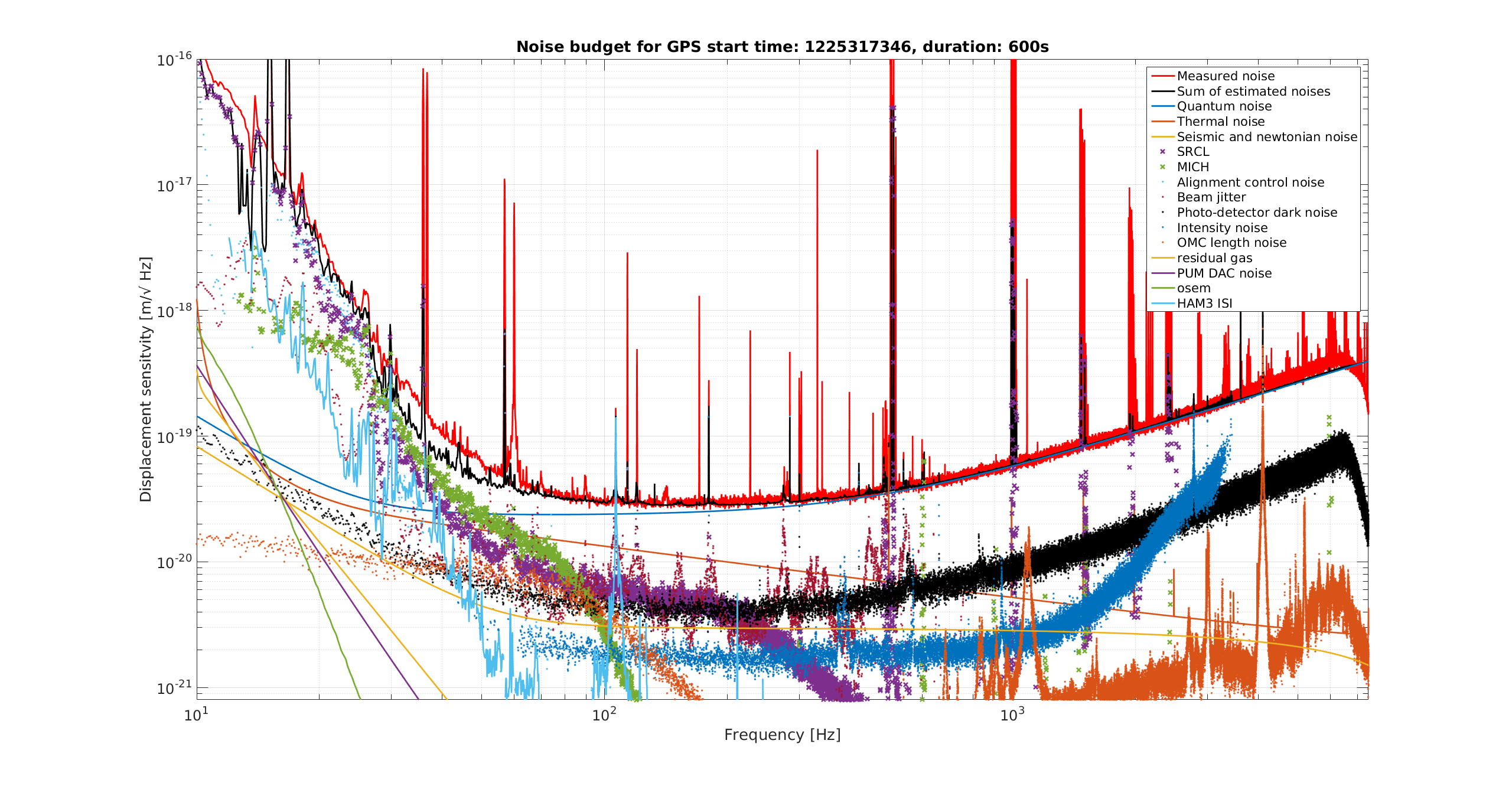
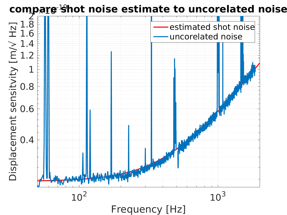
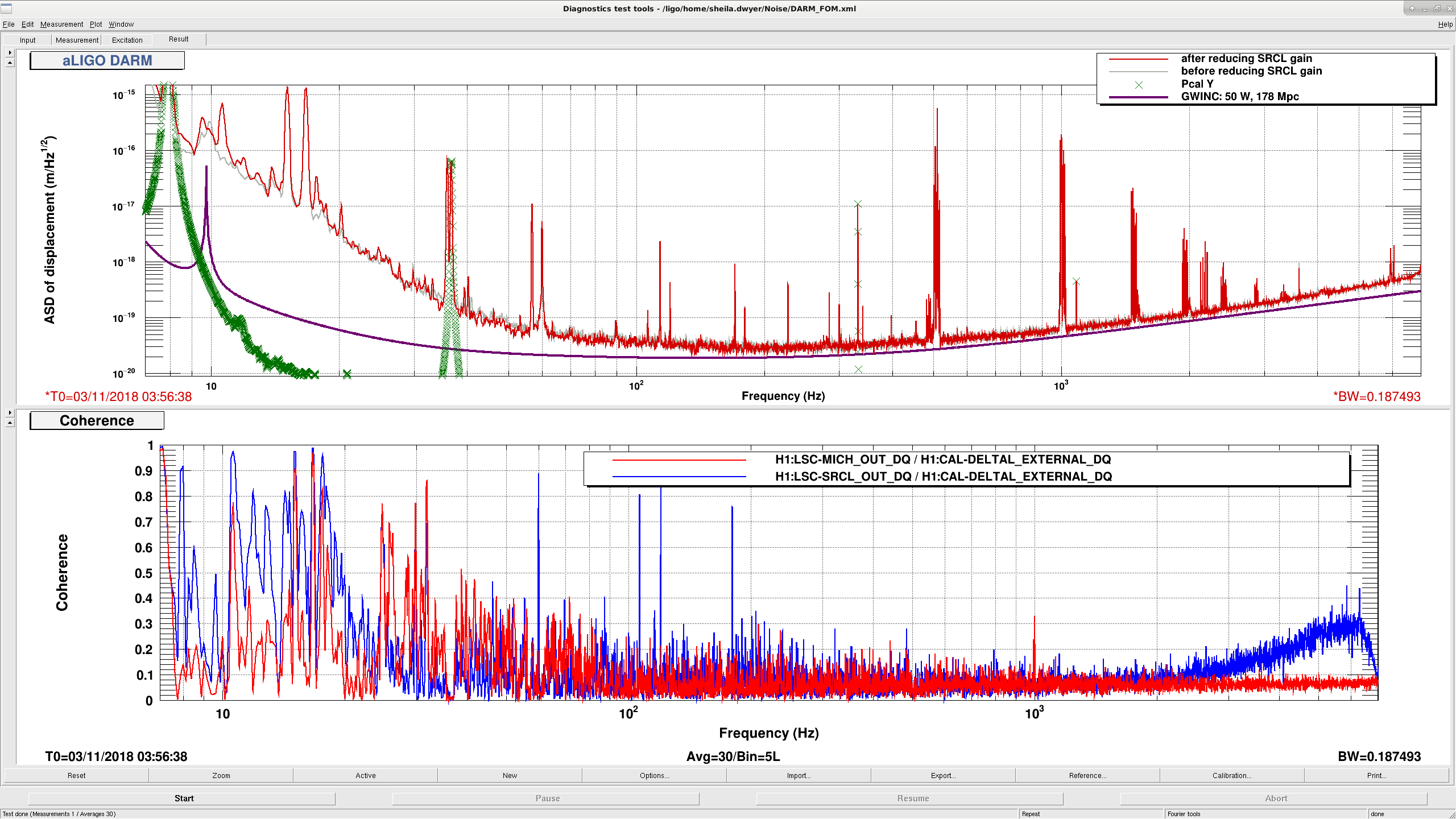
Attached are some plots from an updated noise budget, with several measurements retaken in the last couple of days. 


Last time we posted a noise budget 44840 we were missing an intensity noise measurement, here you can see that intensity noise is making a significant contribution about a few kHz. The second attached screenshot shows the intensity noise injection, which only goes up to 3kHz.  This could be contributing to OMC length noise observed here: 44874

PRC2Y gain reduction

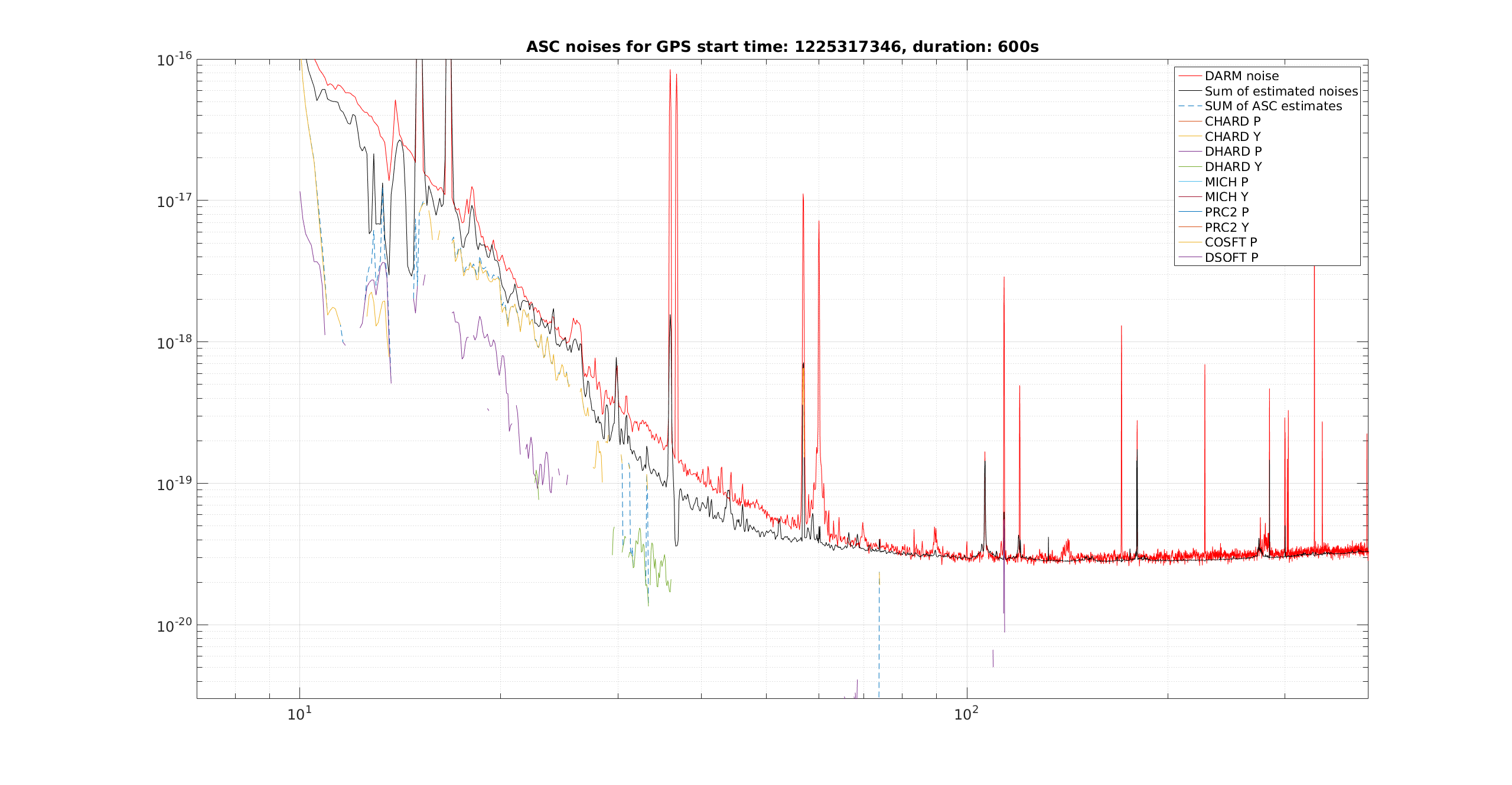
The third attachment shows the ASC noise contributions to DARM, only the PRC2 P+Y measurements have been updated since the last noise budget here. Since PRC2Y was previously dominating the ASC noises, I reduced its gain by a factor of 2 and engaged an 8Hz elliptic low pass, now PRC2Y is not showing up in the plot because it is more than a factor fo 10 below DARM.  

Other notes on the noise budget:  

I also reran the HAM3 injections as well as MICH and SRCL today, those curves are updated in the plot.  

I am still using a guess and check method for the optical gain and cavity pole since we don't have the kappas yet.  This time we are using kappa c = 92% and a cavity pole of 440 Hz. 

Images attached to this report
H1 CAL (CAL)
sheila.dwyer@LIGO.ORG - posted 17:37, Saturday 03 November 2018 (44997)
GDS calib strain spectral leakage

Jamie, Sheila, Craig

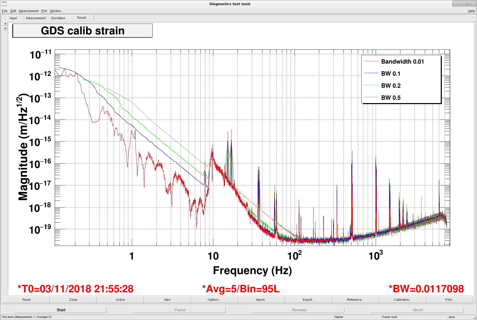
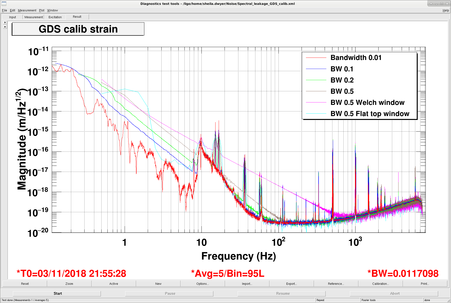
We were updating our noise budget and noticed that the spectrum of GDS calib strain we calculate using pwelch with a hanning window and 5 second FFTs had spectral leakage.  For comparison we took some spectra in DTT and found that with a bandwidth of 0.5Hz we can reproduce the problem in DTT.  The attached screenshot shows spectra taken with different bandwidths and windows. 

It seems like we need more attenuation of the microseism.

Images attached to this report
Non-image files attached to this report
H1 CDS
david.barker@LIGO.ORG - posted 09:07, Saturday 03 November 2018 - last comment - 12:43, Saturday 03 November 2018(44994)
DAC errors on Seismic HAM2,3,4,5 systems (ISI and HEPI) model restarts needed

We have had another DAC issue on h1seih23/45 which will require a restart of all the models on these front end computers.

Would the first person into the control room today please call me on my cell phone and we can get these systems going again.

I have performed all the diagnostics data gathering; as before the first DACs on both systems are reporting empty FIFOs. 

On Tuesday I can install new IOP software on these systems to run through empty fifo errors.

Comments related to this report
david.barker@LIGO.ORG - 12:38, Saturday 03 November 2018 (44995)

Opened  FRS11748 for this issue.

Fault was cleared by restarting all models on h1seih23 and h1seih45. Sheila monitored the restarts from the control room. FRS was subsequently closed. I've marked zero hours lost because issue happened when there were no commissioning activities. If this is incorrect, please edit the FRS accordingly.

david.barker@LIGO.ORG - 12:43, Saturday 03 November 2018 (44996)

In this instance the time sequence was:

GPS local time event

1225270147

Nov 03 2018 01:48:49 PDT

h1iopseih45 DAC-KILL

1225270150

Nov 03 2018 01:48:50 PDT

h1iopseih23 DAC-KILL

Note that the delta time between IOP DAC errors is 3 seconds, for the previous 3 events the deltas were 25, 15, 5 ,so the 'multiples of 5 seconds' pattern has been broken and was presumably coincidence.

H1 ISC
sheila.dwyer@LIGO.ORG - posted 22:39, Friday 02 November 2018 (44993)
locking tonight- improved noise from 60-100 Hz

Georgia, Craig Sheila


Images attached to this report
H1 ISC
sheila.dwyer@LIGO.ORG - posted 20:11, Friday 02 November 2018 (44991)
SRCL noise summary

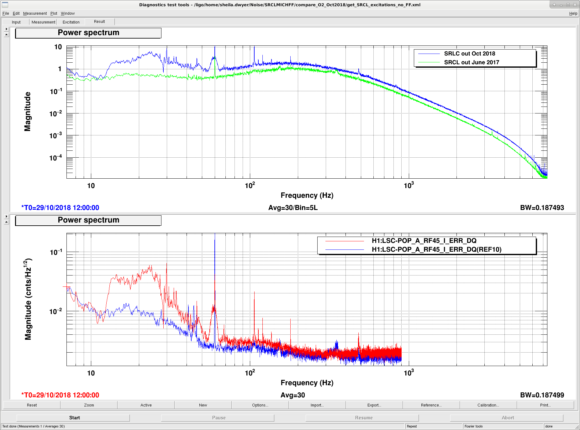
In our DARM noise budget, both SRCL and MICH noises are higher than they were during O2, and are limiting our noise right now.  Here I am just summarizing some information about the SRCL noise.  

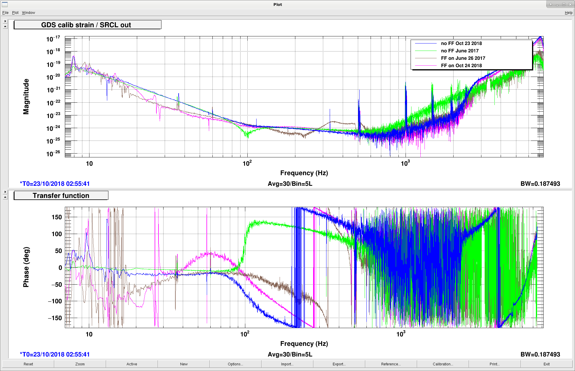
In the first attachment, you can see that the coupling of SRCL control signal without feedforward on is very similar now to what we had in June 2017 (blue and green traces).  The brown and pink traces show the coupling with feedforward on, you can see that the feedforward now is actually doing a slightly better job than we were doing in O2 from 40-100 Hz.  

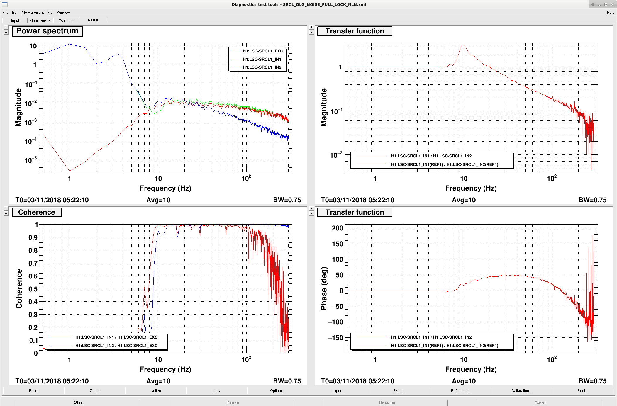
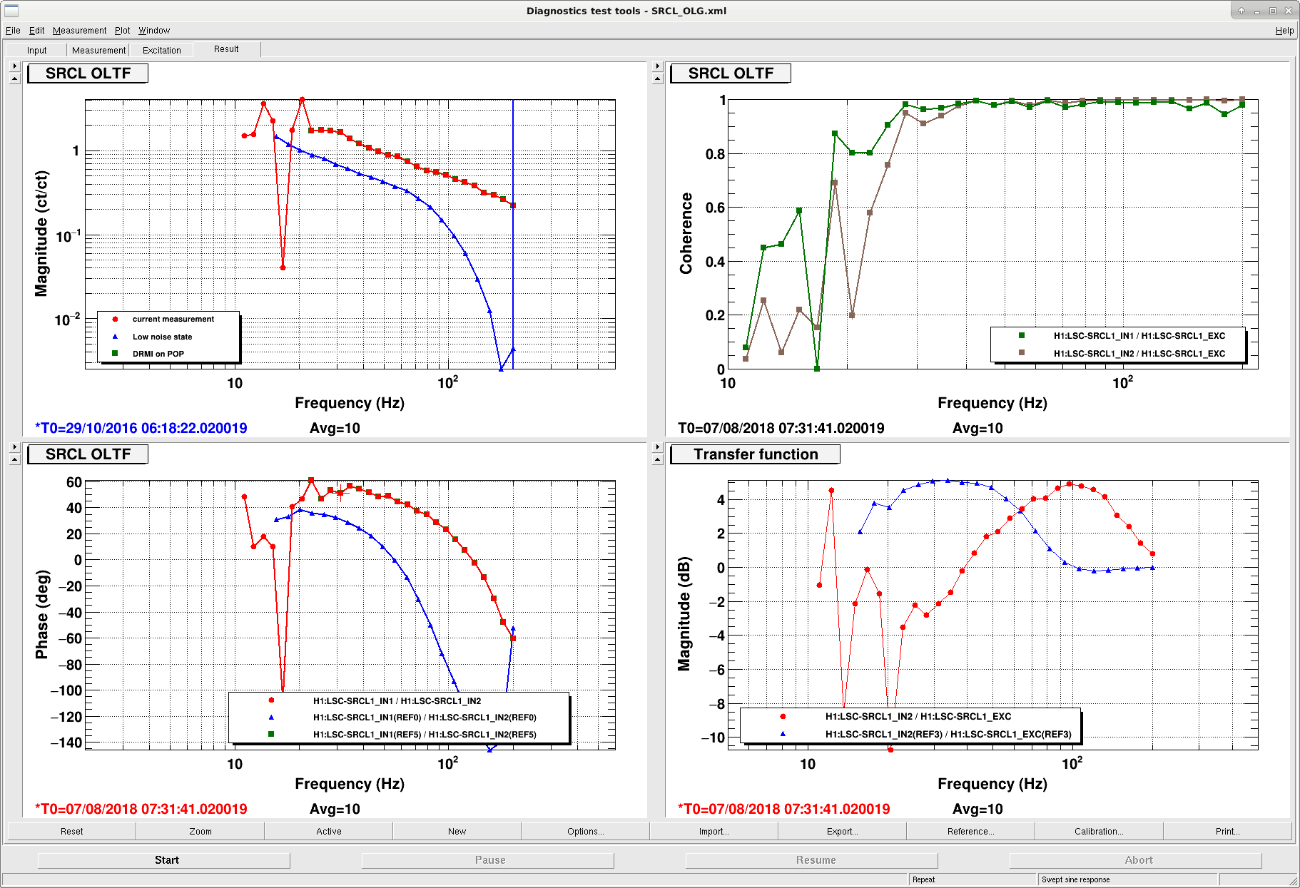
In the second attachment, you can see that the SRCL control signal is now larger than it was in O2.  The lower panel shows the signal out of the sensor.  We changed the whitening gain from 30dB to 21dB, (we now compensate for the whitening gain in the digital gain but we didn't in O2, the gain change is corrected for in this plot). 

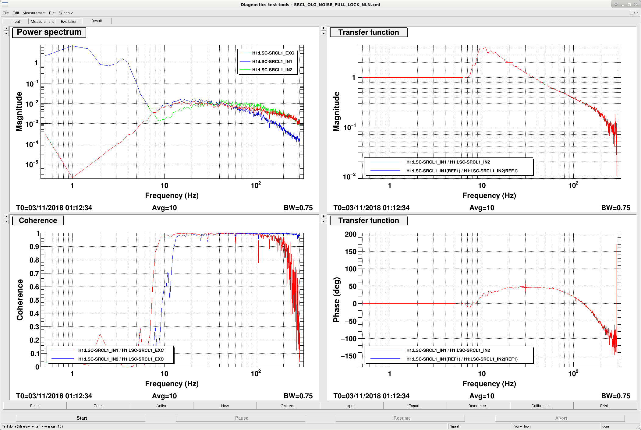
Above 70 Hz, the control signal is about a factor of 2 above what it was in O2.  This makes sense, because our UGF is about a factor of 2 higher than it was in O2.  (See 3rd and 4th attachments, and the OLG posted by Evan Hall here: 24933

Below 70Hz or so, there is excess noise.  Much of this noise is due to HAM3 motion (see Georgia's measurement in 44393 and the comment from Hang).  We were able to reduce this noise in SRCL by tuning the PRCL subtraction in the input matrix (44893), however, the tuning seems to be changing from lock to lock so that we are not able to use a consistent input matrix to get rid of this noise.  

Images attached to this report
H1 ISC (ISC)
hang.yu@LIGO.ORG - posted 17:24, Friday 02 November 2018 (44990)
REFL/POP power & SRCL/PRCL noise vs. PRG in FINESSE

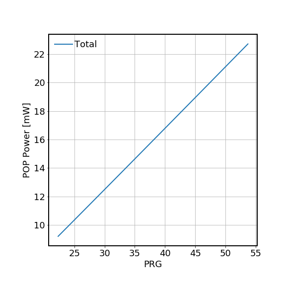
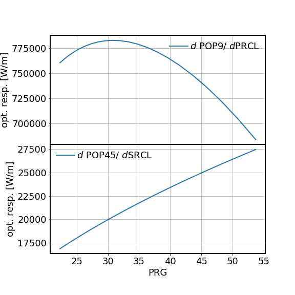
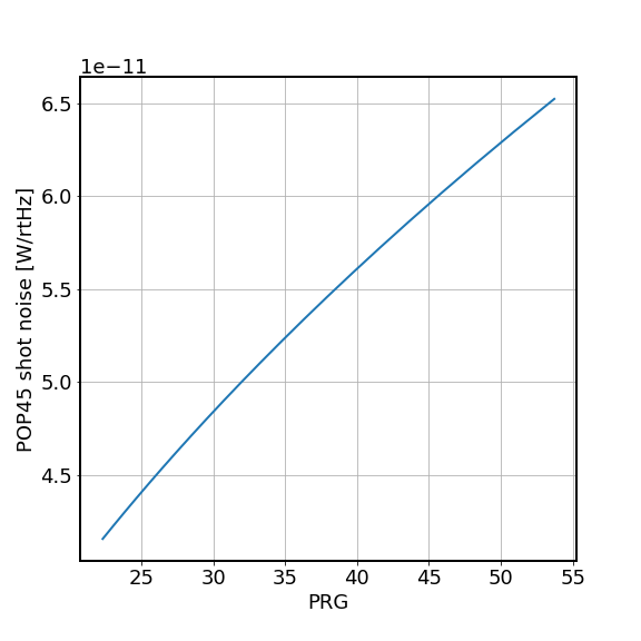
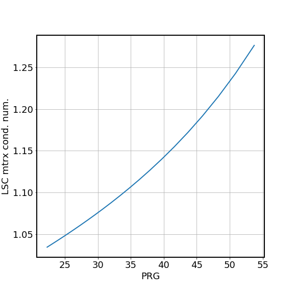
We did some FINESSE modeling to see the power/noise/optical response at the REFL/POP port in the NLN state.

=====

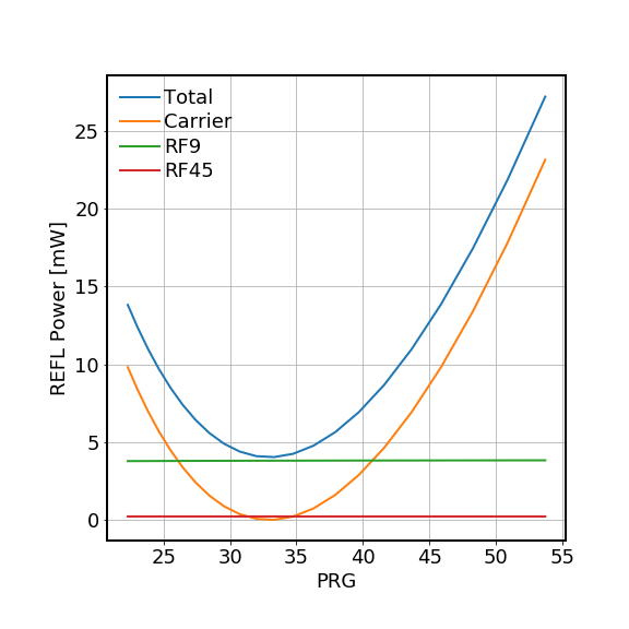
In the first plot we show REFL port power as a function of power-recycling gain (PRG). In addition to the total power, we also show the contributions from the carrier, RF9, and RF45 individually. The simulation result is very similar to the analytical estimation did in LHO:44410 (the RF45 contribution in this entry is lower than previously estimated as we assumed the NLN here and thus here we have extra 6 dB reduction in RF45 mod. depth). However,  the measured REFL power (LHO:44947) is lower than the model by about a factor of 2...

Also note that as the carrier is no more critically coupled, the shot noise level (in [W/rtHz]) will go up by almost factor of ~ sqrt(4) = 2 due to the increased amount of REFL power. However, the signal strength for, e.g., CARM will only go up by ~ sqrt(46/33) ~ 1.2. Therefore we might expect to lose a factor of 2/1.2 ~ 1.7 in CARM sensitivity...

=====

For the LSC_POP DC power the model and measurement seem to agree well. See the second plot. 

=====

In the third plot we show the expected optical response for POP9 to PRCL (top), and POP45 to SRCL (bottom). Those values are calibrated to [W/m]. For PRCL we see the response decreases as the PRG increases. This is expected because as the PRG goes up, the difference in the PRC finesse as seen by the carrier field and by the RF9 filed gets reduced. For POP45 to SRCL, the signal strength increases as we improve the PRG.

=====

In the forth plot is the shot noise level of the POP45 signal in [W/rtHz]. 

We also consider how well we can invert the response matrix of POP9/POP45 to PRCL/SRCL as the PRG changes. The condition number of this response matrix is shown in the fifth plot. Here to compute the condition number, we normalized the response such that the max. resp. to a dof is normalized to 1 (such normalization is equivalent as we having a freedom to choose an overall scalar at the input matrix). For example, the normalized resp matrix at PRG of 46 is given below,

norm'ed resp matrix POP9 POP45
PRCL 1 -0.17
SRCL 0 1

which leads to a condition number of 1.2. The larger the condition number, the harder the inversion of matrix (and thus the higher the sensing-noise-limited sensitivity).

=====

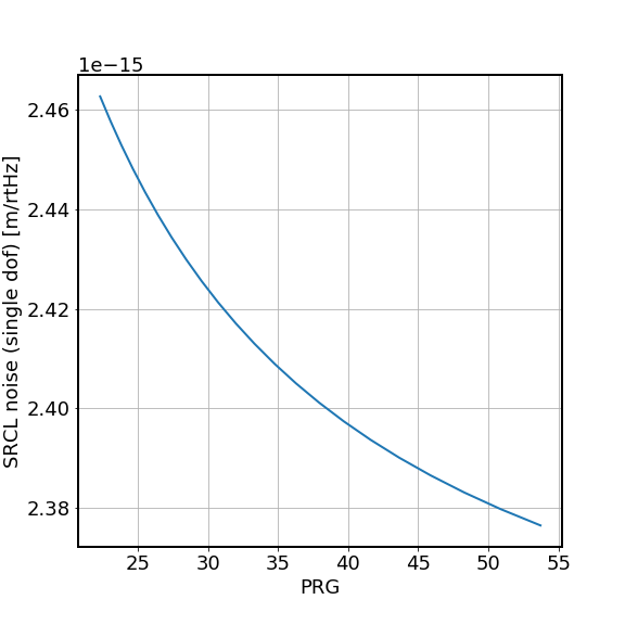
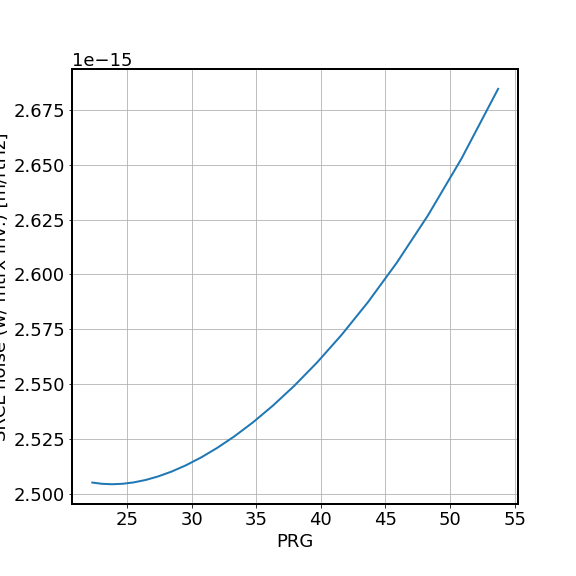
In the last two plots we showed the SRCL noise. In the second last one we simply take the POP45 noise in [W/rtHz] divided by its response to SRCL in [W/m]. In this case we see that the shot-noise-limited SRCL sensitivity improves slightly. However, this assumes that we do not need to do any matrix inversion, which is unrealistic as we do not have a significant gain hierarchy between the corner dofs. 

In the last plot we show SRCL noise, taking into account that the condition number gets worse as the PRG goes up (by multiplying the single dof shot noise with the sqrt of the matrix condition number as an approximation). However, the SRCL noise is worsen by only a few %. Effectively it should not change from now to O2. 

=====

Parameters used in the simulation:

T_prm = 0.031, T_itm = 0.014, T_srm=0.325. The PRG variation is achieved by varying the common losses of the arms. 

For the modulation depth, we assumed Gamma_9 = 0.19 and Gamma_45 = 0.25 * (-6 dB) = 0.125, as in the NLN we reduced the RF45 mod. depth by 6 dB.

We assume that 1.25% of the power refl'ed from the ifo is delivered to the refl PD. For POP, we assumed T_pr2=230 ppm and 9% of the pop beam goes to POP QPD. 

Perfect mode matching is assumed for this study. 

Images attached to this report
H1 ISC (ISC)
georgia.mansell@LIGO.ORG - posted 23:42, Thursday 01 November 2018 - last comment - 07:40, Thursday 08 November 2018(44972)
PR2 camera spots

[Sheila Cheryl Keita Georgia]

After discovering the coupling between HAM3 and DARM we were curious about the beams that we see on the PR2 camera and whether they can help us identify sources of clipping and backscatter. We see a few beams in this camera image that we would like to identify.

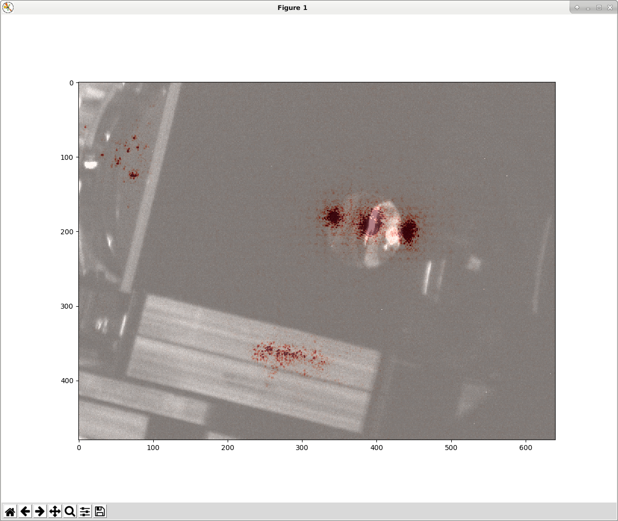
We haven't zoomed or moved the PR2 camera since we last tried to identify these spots in July. I used Gabriele's script to superimpose the camera image we see now, at 20W, with the visible image. See attached screenshot.

There are 4 spots visible on the PR2 scraper baffle: it looks like 3 at first glance but I think the central spot has a smaller spot slightly above it, the intensity of this smaller spot fluctuates during the lock. To check that these spots were not coming from the MC2 transmission we locked the mode cleaner at 25 W, and did not see these spots with anywhere near comparable intensity.

In the visible image, looking through the hole in the scraper baffle, with think we can see the outline of a round mount which could be the 3" mirror directly behind PR2. Visible in the 3" mirror we think we can see the reflection of a mount that could be the first to the first mirror on the POP QPD path. I'm not sure if any other beams we see on the camera are actually coming from these mirrors though.

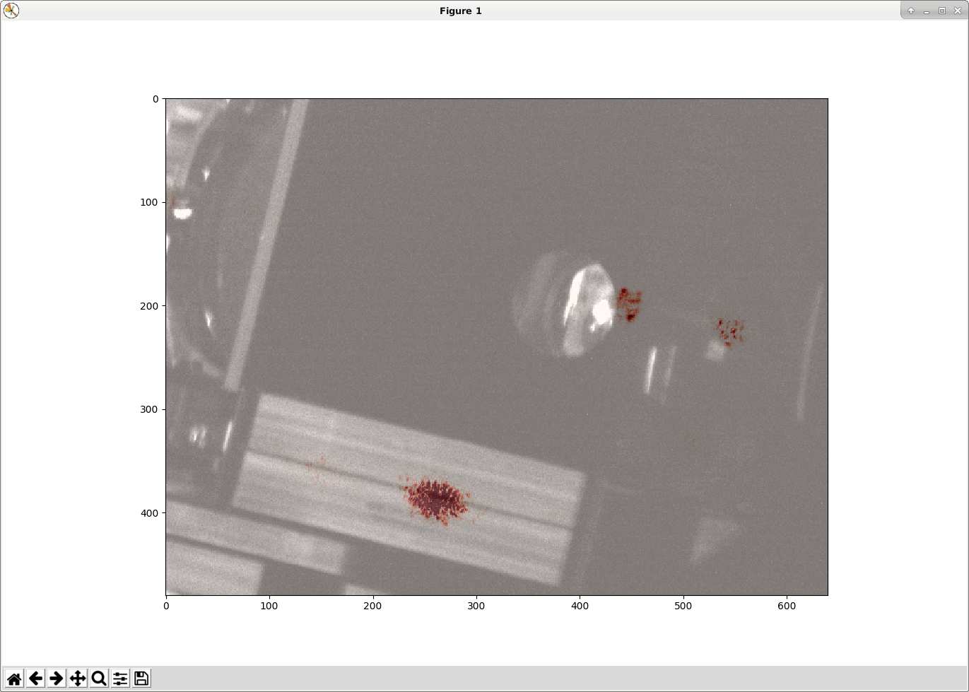
There is also some light visible on the balance mass, which Keita and Sheila hypothesize could be a reflection off the AR surface of an ITM, which is wedged such that the thin part is on top, which is reflecting off PR3 and is not getting caught by the scraper baffle. When ALS is locking/locked we also see spots on the balance mass, from both the X and Y arm green. This is shown in the second attached screen shot. The other spots visible in the second screenshot are also green.

On the left we also see some spots which might be coming from the beamsplitter elliptical baffle.

Images attached to this report
Comments related to this report
jeffrey.kissel@LIGO.ORG - 08:24, Friday 02 November 2018 (44977)
Associated with FRS Ticket 11740.
georgia.mansell@LIGO.ORG - 20:22, Friday 02 November 2018 (44992)

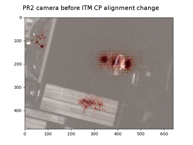
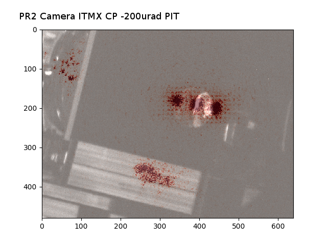
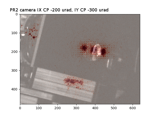
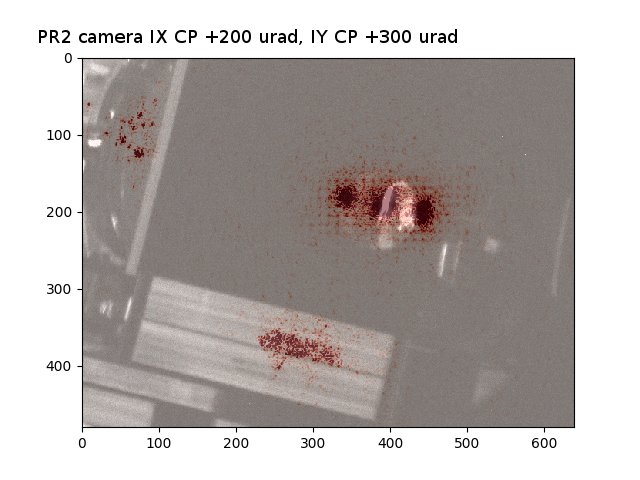
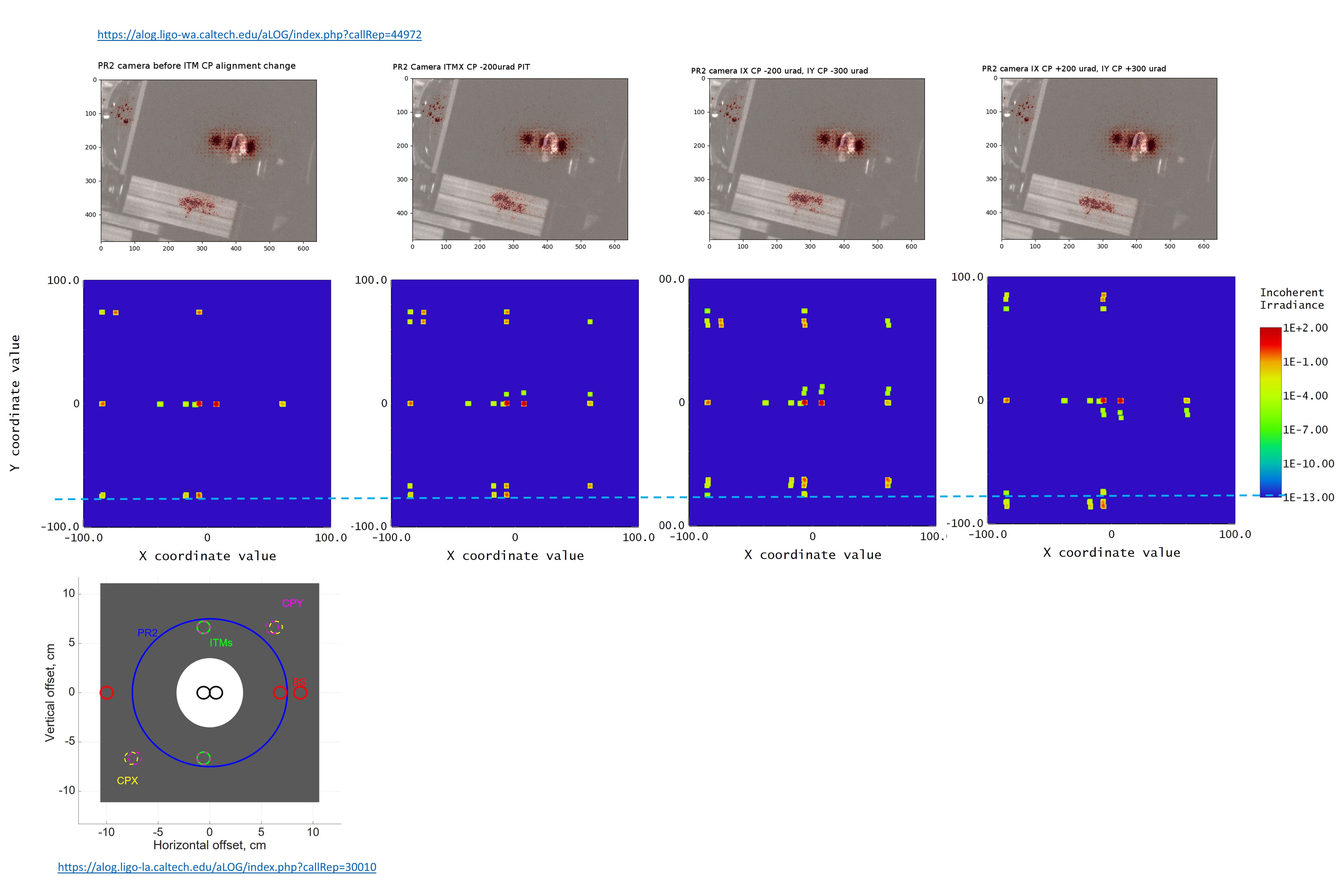
On Anamaria's suggestion we tried steering the ITM compensation plates and looking at the spots on the PR2 camera.

The spots on the ballast mass originate from both CP's. See attached photos:

1.before the CP move

2. with only the IX CP pitched (-ve)

3. with both ITM CP's pitched (-ve)

4. with both ITM CP's pitched (+ve)

Images attached to this comment
calum.torrie@LIGO.ORG - 08:26, Monday 05 November 2018 (45011)

Please see attached pdf for the overlay and identification of IFO items seen in Georgia's alog picture. (Sent previously via e-mail and now posted here for record.)

Eddie and Calum

Non-image files attached to this comment
calum.torrie@LIGO.ORG - 08:36, Monday 05 November 2018 (45012)

Again previously on e-mail and adding here for record ...

From Corey Austin:

Those are second order ghost beams from ITM-AR and/or CP (so ITM-AR->ITM-HR->ITM-AR->PR3->masses). The attached slide shows pictures taken at LLO in full lock before/after we added a baffle in front of those masses during our last vent.

LLO has a 'tie-fighter' shaped spot on our camera that we decided was coming from the beamsplitter which may be your 3 beams.

From Alena / Calum / Eddie:

For future use /  reference LHO has that baffle Corey refers to (before / after pics attached again) on the shelf at LHO. To see it in more detail (at LLO) see table baffle on pg. 3, Detail 'D' of  LIGO-D0900520-v14 (https://dcc.ligo.org/LIGO-D0900520) and yes you have to be careful with placement so as not to clip the main beam!

From Calum:
Thought these would be a useful reminders too
(i) Den's previous post on Ghost beams: https://alog.ligo-la.caltech.edu/aLOG/index.php?callRep=30010
(ii) and that the PR2 scrapper Baffle D1000328 is designed to catch the ghost beams from BS, CP and ITM as per Den's images in above log.


Non-image files attached to this comment
calum.torrie@LIGO.ORG - 07:07, Wednesday 07 November 2018 (45086)

Hiro, GariLynn and I had been discussing the ghost beams around PR2 and Hiro looked into the BS ghosts due to the wedge, see below and attached.

From Hiro:

The ghost beam around PR2 due to the wedge of BS is 90mm from the center of PR2.

 
Non-image files attached to this comment
alena.ananyeva@LIGO.ORG - 07:40, Thursday 08 November 2018 (45117)
Attaching Zemax simulations for all four conditions:
1 - detector view in front of PR2 baffle before ITM CPs alignment change
2 - detector view in front of PR2 baffle ITMX CP -200 um pitch
3 - detector view in front of PR2 baffle ITMX CP -200 um pitch and ITMY CP -300 um pitch
4 - detector view in front of PR2 baffle ITMX CP +200 um pitch and ITMX CP +300 um pitch

The detector is looking in both direction, the model does not have the baffle spacer and ballast masses therefore in zemax we may see more beams than on camera photos. The group of ghost beams highlighted with a dashed line matches the ghost beams seen on the mass in front of the baffle.
Adding a simulation of the ghost beams in front of PR2 baffle from an older aLog https://alog.ligo-la.caltech.edu/aLOG/index.php?callRep=30010 [Denis Martynov]
Images attached to this comment
Displaying reports 44741-44760 of 88438.Go to page Start 2234 2235 2236 2237 2238 2239 2240 2241 2242 End