patrick.thomas@LIGO.ORG - posted 16:00, Tuesday 30 October 2018 (44924)
Ops Shift Summary
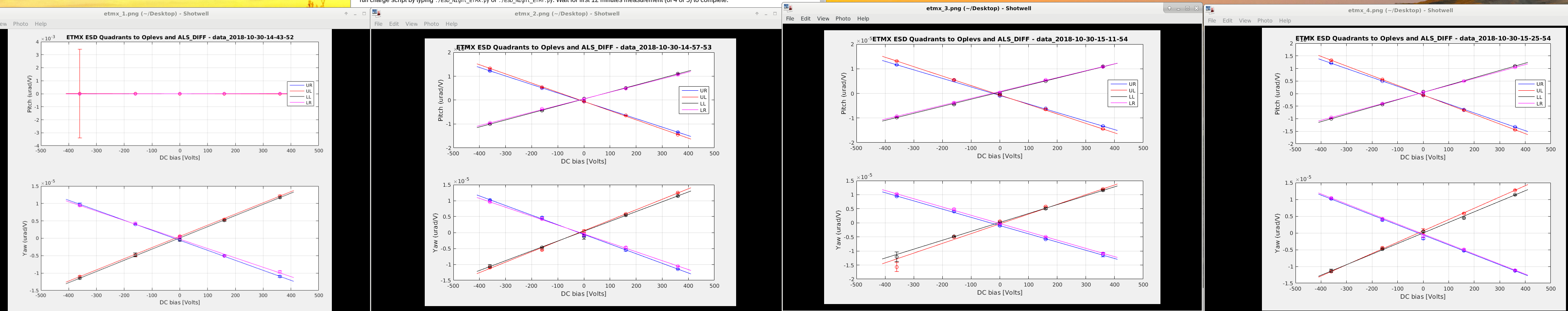
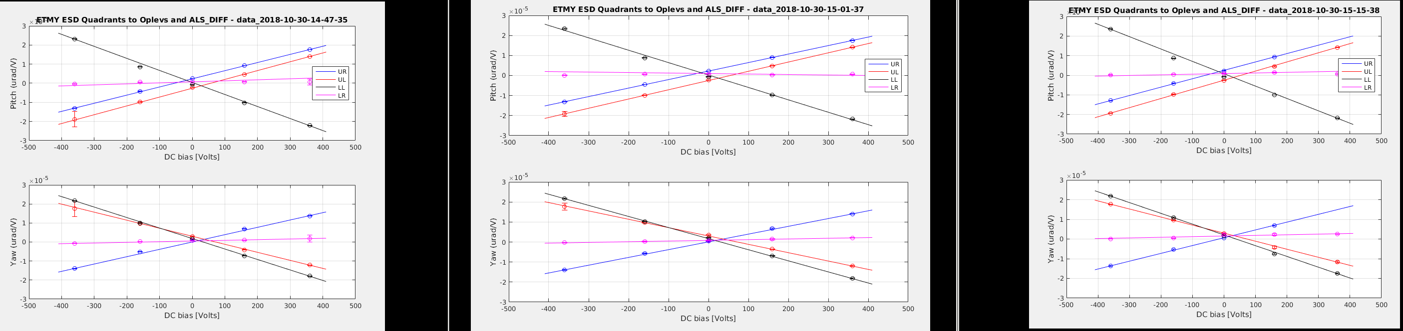
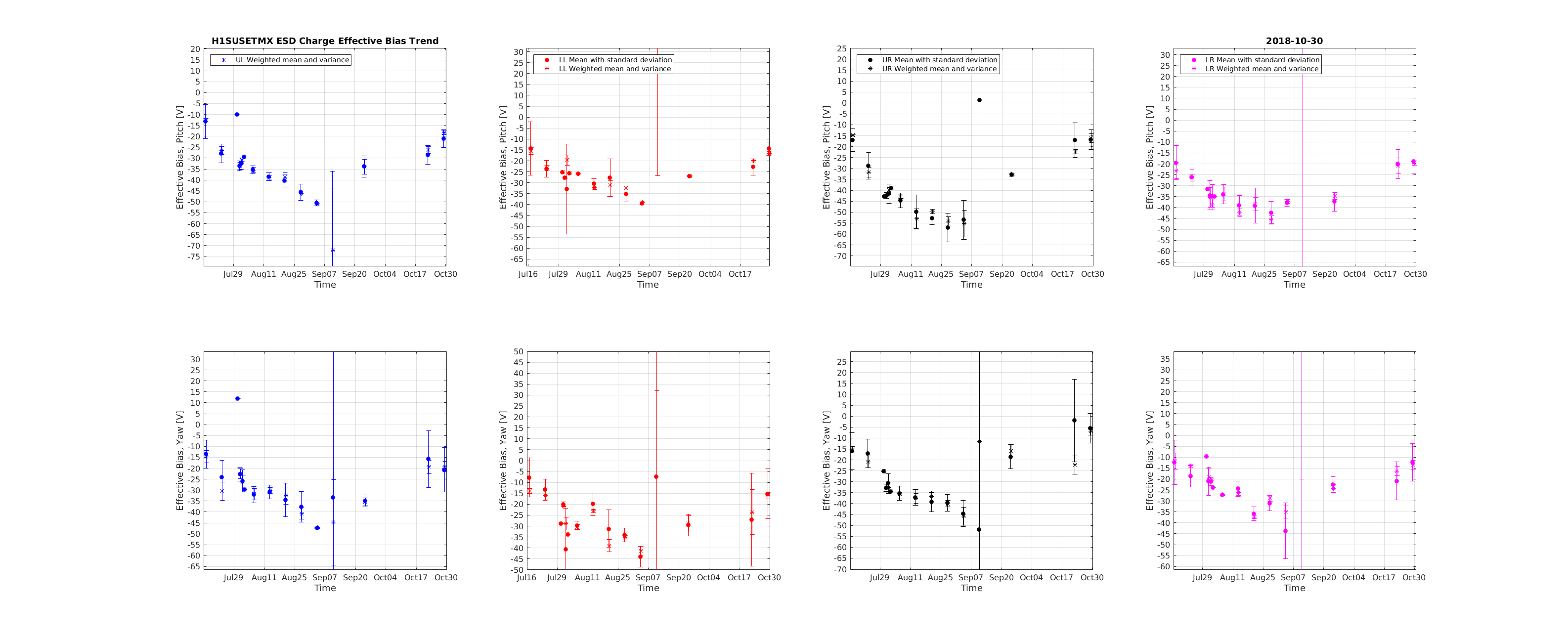
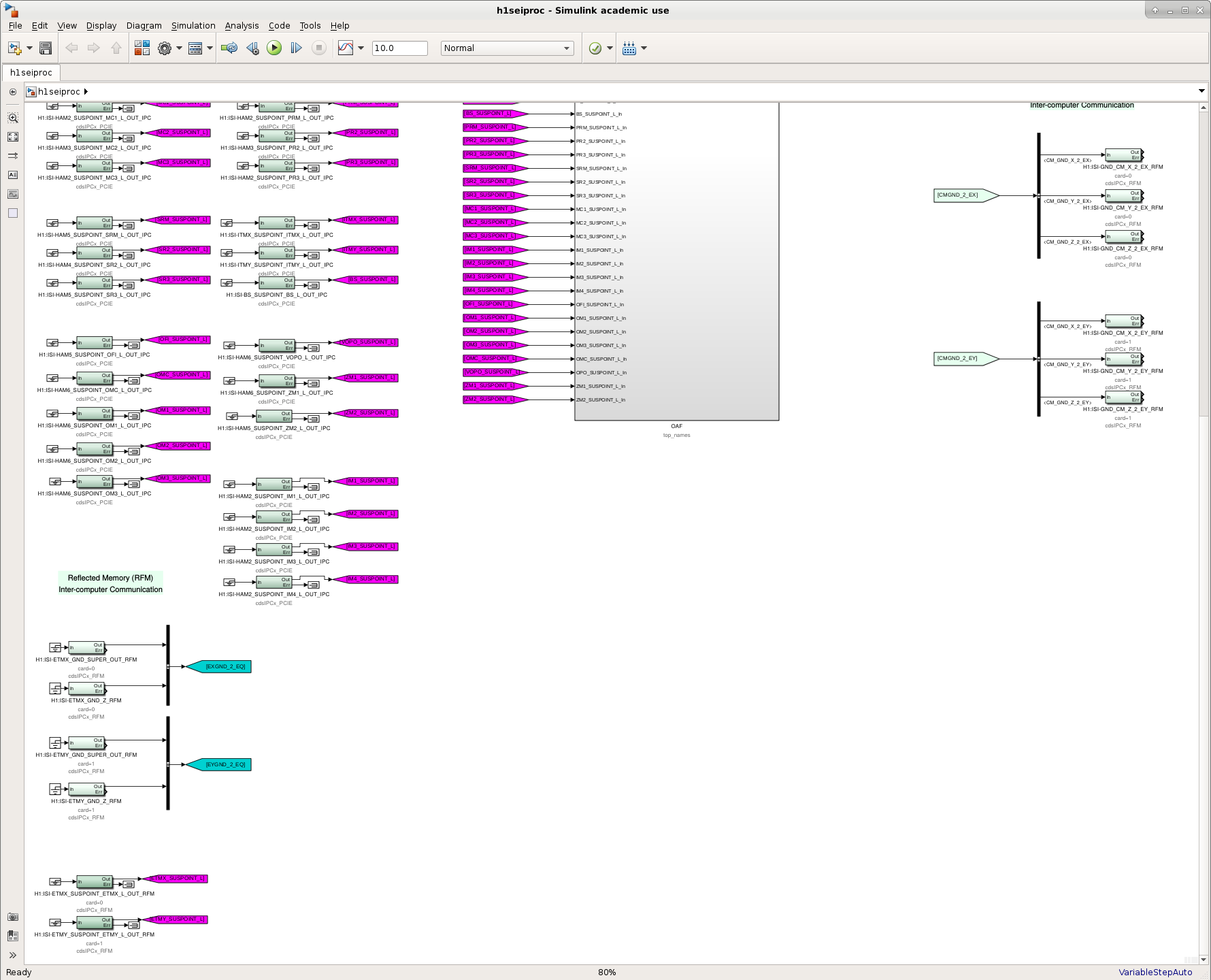
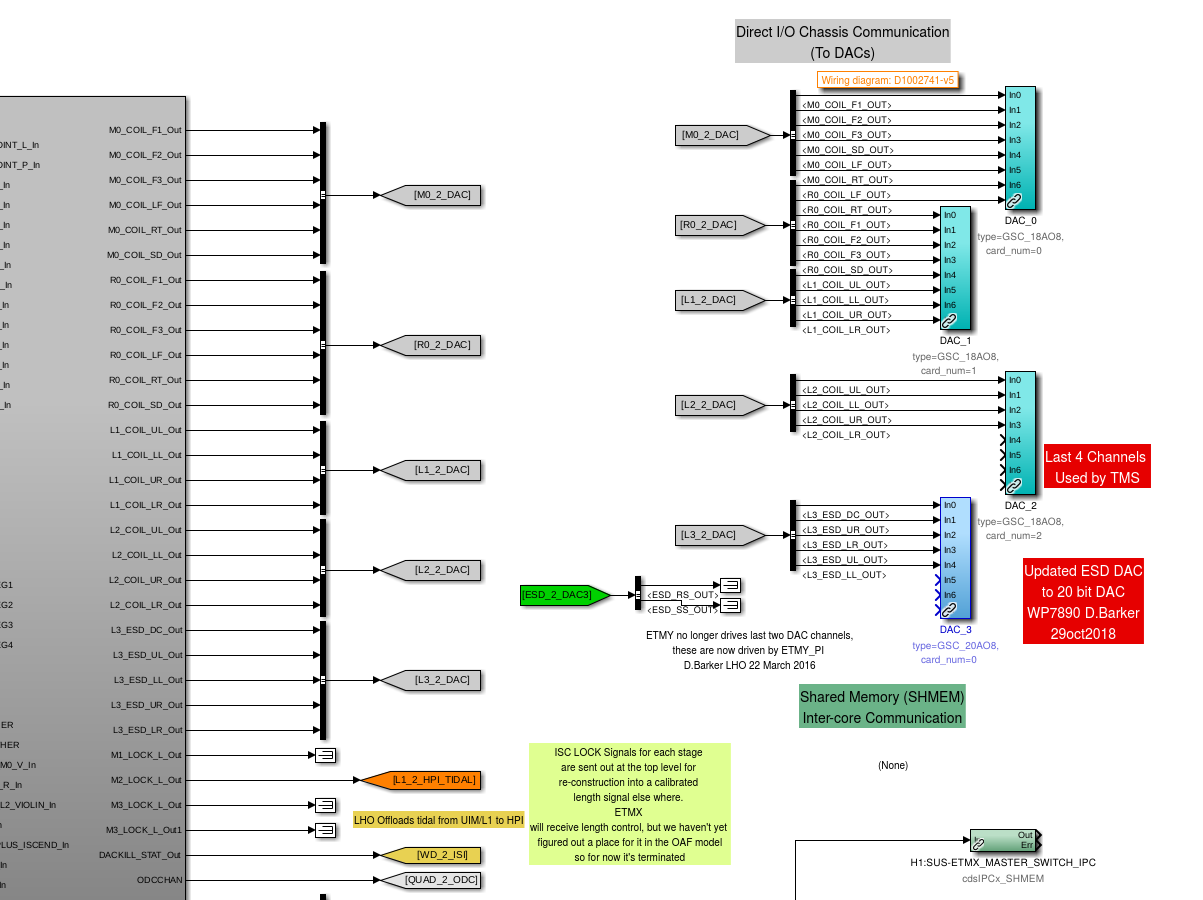
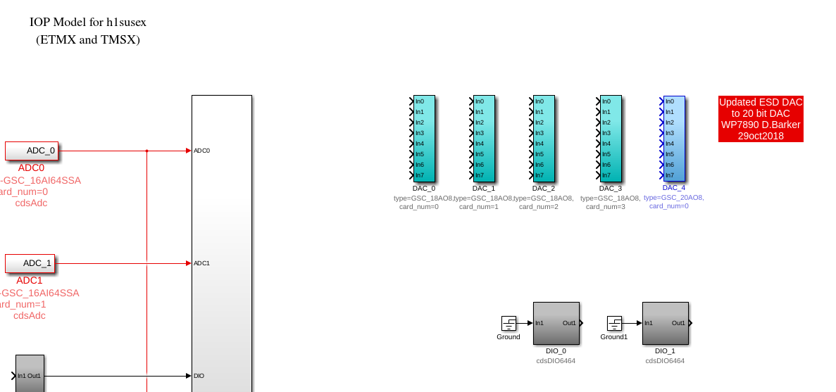
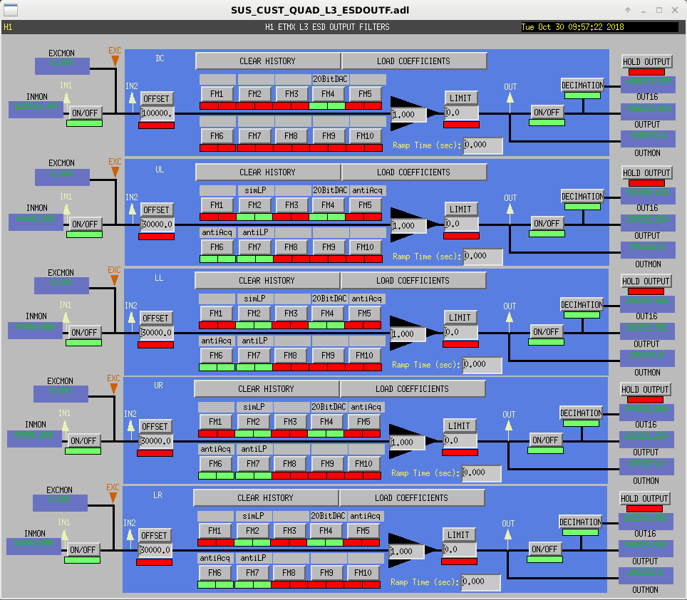
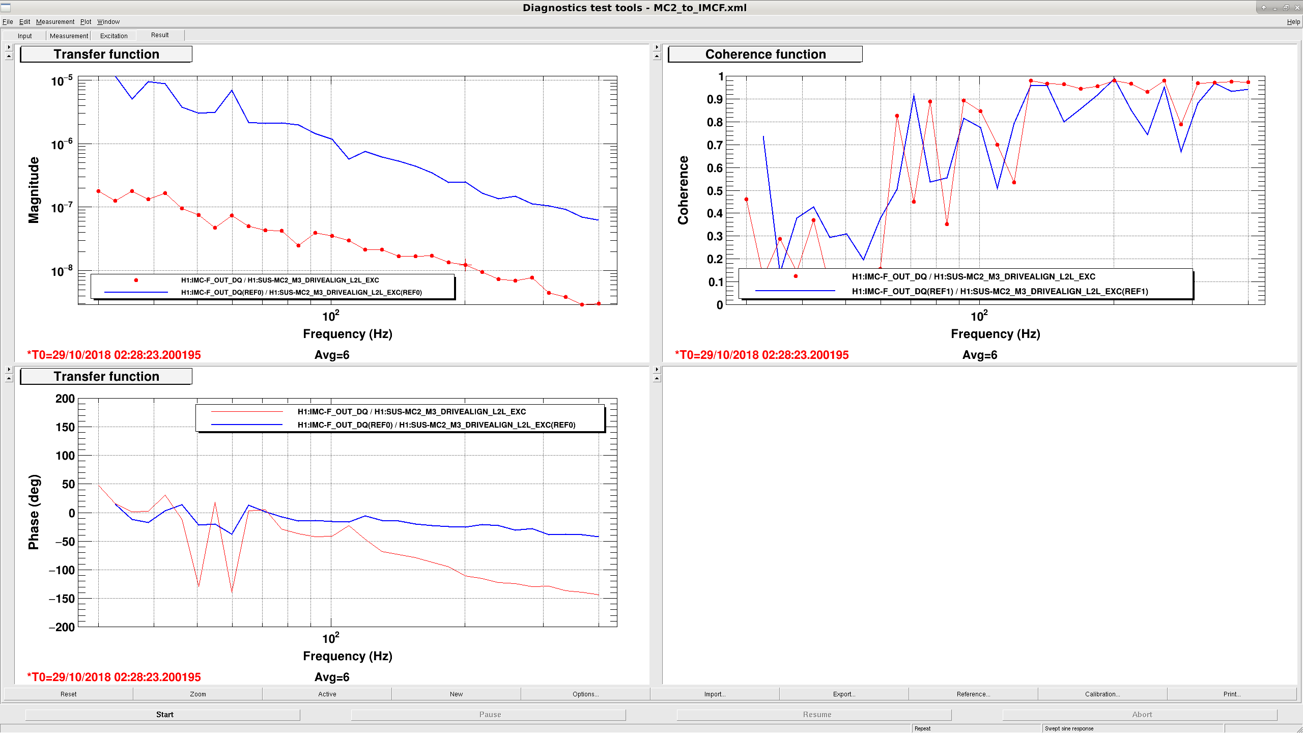
14:16 UTC Chris S. starting at end X supply fan room to grease fans. In order end X, mid X, mid Y, end Y
14:27 - 16:12 UTC Corey running charge measurements
14:36 UTC SEI config to SC_OFF_NOBRSXY
14:37 UTC Ran dust monitor check. All report OK.
15:00 - 15:38 UTC Kyle to end Y to start pumps on BSC10
15:14 UTC Vanessa to LVEA
15:29 UTC LN2 delivery
15:35 UTC Set HAM 2 ISI to DAMPED. Ed and Filiberto to HAM1,2 for cabling
15:42 - 18:43 UTC TJ, Thomas to LVEA, opening HWS table, taking pictures
15:44 UTC Jason to PSL enclosure, DBB work
15:56 UTC Cheryl to PSL enclosure
16:10 - 17:22 UTC Hugh to end stations, HEPI maintenance
16:10 UTC Marc to join Fil
16:17 UTC Jim to end X, BRS
16:18 UTC Jeff J. to LVEA, safety inspect
16:25 UTC SUS ETMX, TMSX to safe. Dave, SUS ETMX model restart, 20 bit DAC
16:25 UTC Corey to join Cheryl
16:27 UTC Vanessa to endX, endY
16:33 - 17:13 UTC Bubba to LVEA, 3IFO inspection
16:38 UTC h1calcs model change
16:42 - 18:50 UTC Chris to LVEA, forklift charging, etc.
16:44 UTC Christina, forklift by VPW
16:58 UTC Richard to mechanical room to look at heater circuits
16:58 UTC Terry to ISCT6
16:59 - 18:58 UTC Dick to ISC racks, RF measurements
16:59 UTC Nutsinee to ISCT6
17:08 UTC Jeff J. to end Y, safety inspect
17:22 - 17:30 UTC Hugh to LVEA to locate tools near squeezer bay
17:30 - 17:40 UTC Tour in CR
17:31 - 17:57 UTC Richard to mechanical room
17:40 - 18:06 UTC Gerardo to mid and end stations, checking for filters on fan exhaust
17:50 UTC Ed, Filiberto done, heading to end X to terminate cables
17:52 UTC HAM2 to isolated
17:54 UTC Dave, Jeff restarting ETMY SEI model
18:10 UTC Observatory mode to preventive maintenance, thought I had earlier
18:12 UTC Greg, DMT update
18:14 - 19:01 UTC Ed and Fil at end X, cable work, turning HV off
18:18 UTC DAQ restart
18:39 - 19:11 UTC Dave to end Y
19:20 UTC Pepsi truck through gate
19:23 UTC Corey, Cheryl and Jason done in PSL enclosure
19:30 UTC Observatory mode to locking
19:41 UTC DAQ restart
19:45 UTC ISI config to WINDY, starting initial alignment
20:27 UTC Restarted video0
20:42 UTC Greg M. done calibration update
20:58 UTC Observatory mode to commissioning
21:53 - 22:33 UTC Gerardo to end X fan room