jeffrey.kissel@LIGO.ORG - posted 13:14, Sunday 28 October 2018 - last comment - 19:08, Sunday 28 October 2018(44866)
Added 30k Offset to ETMX ESD Output, 18 bit DAC Glich Avoidance
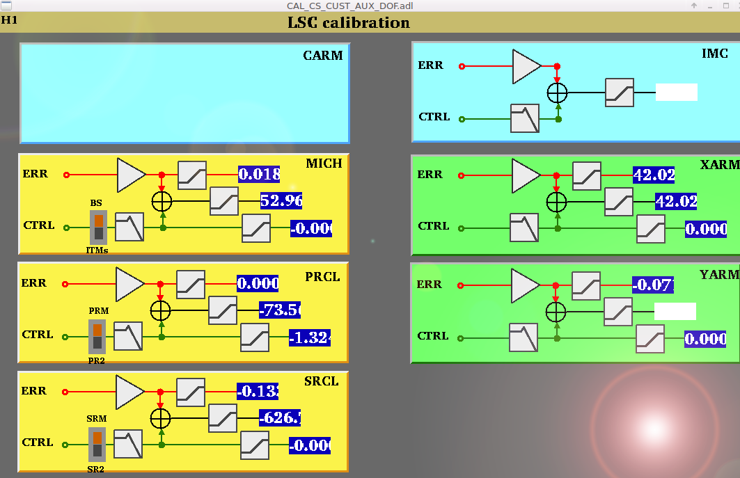
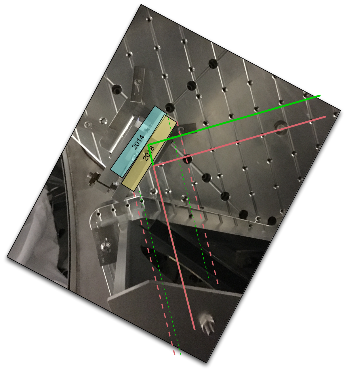
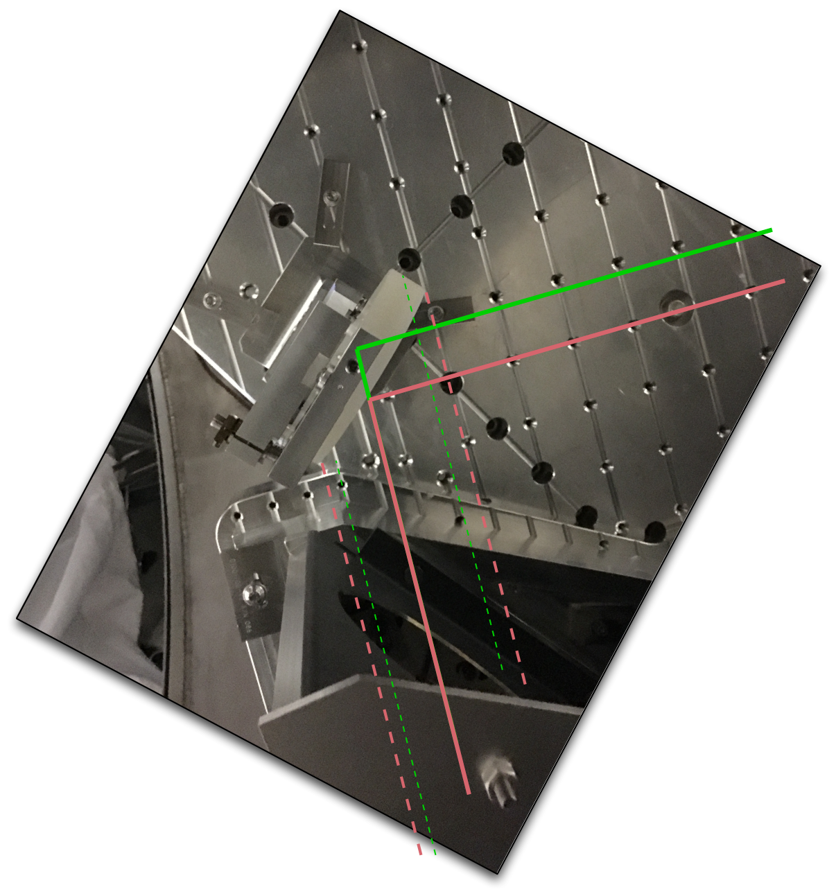
J. Kissel
#SundayInvestigations

Rana and Gabriele had the IFO running when I came in, and we meandered through discussing "status of the IFO" topics. After seeing many glitches in the otherwise stable IFO, I realized we haven't turned on any offsets on the ETMX ESD stage that had on the ETMY ESD during O2 that helped avoid zero-crossings of the 18 bit DACs (mostly because the 20-bit DACs were recently on my brain; see ECR E1800306).

Thus, while the IFO was locked and in nominal low noise, with a ramp time of 60 seconds, I turned on a +30000 ct offset (~1/4 the range) on each of the UL, LL, UR, and LR quadrants in the ESDOUTF banks (see attached screenshot).
I haven't accepted this into the SDF system, because I have no idea if this a source of some of the glitches we're seeing. If we find we like it, we'll then keep it for real.

This went in around 2018-10-28 20:00 UTC. The IFO had been locked and at low noise for ~30 minutes or so prior to this with no one doing anything. No one's touching it now (for at least 30 minutes), so this should be a good chunk of time to compare ON vs. OFF.
It would be great if @DetChar would use some of their techniques for investigating and finding zero-crossing glitches to see if this was actually a problem, and if these offsets improved things.
Images attached to this report

Comments related to this report
I lost lock twice at LOWNOISE_ESD_ETMX with the verbal warnings "PRM; MC2" before losing lock.  I turned off these offsets at around Oct 29 2018 02:06:41 UTC, we'll see if this helps relock.
If we decide we still want these offsets (which we may not), we should probably switch them on in guardian after switching to the lownoise ESD.

EDIT: After turning these off we were able to get to NOMINAL_LOW_NOISE.