[Jenne, Gabriele]
We might be limited by intensity noise that we can't sense with the ISS first loop diodes. Now that we got your attention, see the details below. The most interesting plot is the last one.
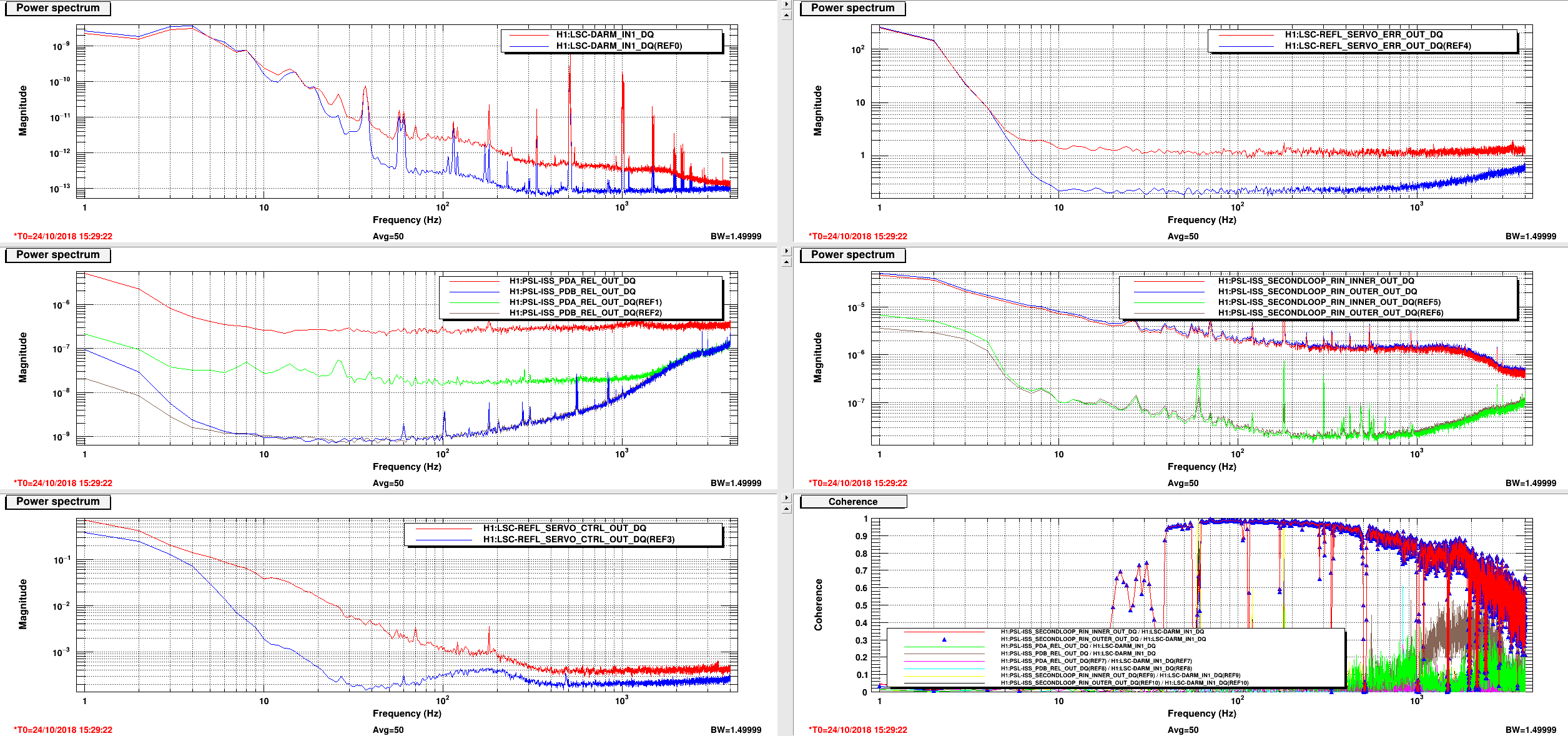
This morning we checked whether the ISS second loop was open. The output switch of the second loop board (H1:PSL-ISS_SECONDLOOP_OUTPUT_SWITCH_MON) was indeed open, but the input switch on the first loop board was closed (H1:PSL-ISS_SECONDLOOP_CLOSED). So we decided to open it.
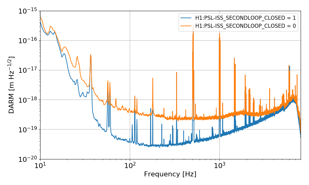
We were surprised to see that the sensitivity got significantly worse when the switch was open. See below (H1:PSL-ISS_SECONDLOOP_CLOSED = 1 means switch closed, first loop closed but second loop still open at the output of the second loop board, H1:PSL-ISS_SECONDLOOP_CLOSED = 0 means switch open at the input of the first loop board, but the first loop is still closed)
At the same time we see that the first loop signals (PDA is out-of-loop and PDB is in-loop) also changed. The in-loop signal did not show any difference, while the out-of-loop signal noise floor increased by about a factor of ten. See below (top panel is again DARM, bottom panel is the in-loop signal (dashed) and the out-of-loop signal (solid).
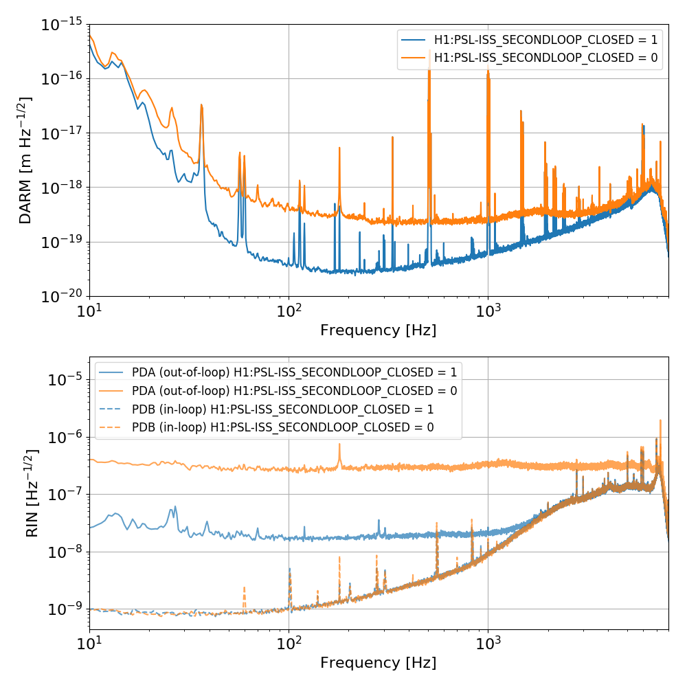
So it looks like the noise in DARM increased at almost all frequencies by about the same factor as the noise seen by the ISS first loop (out-of-loop) PDA sensor.
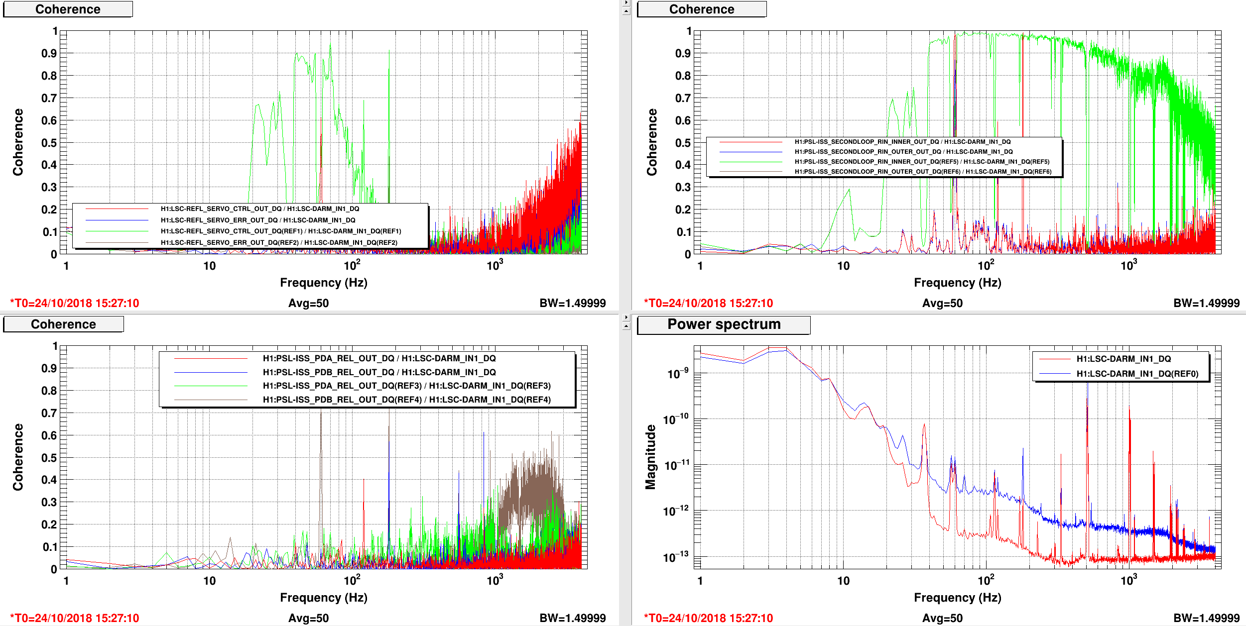
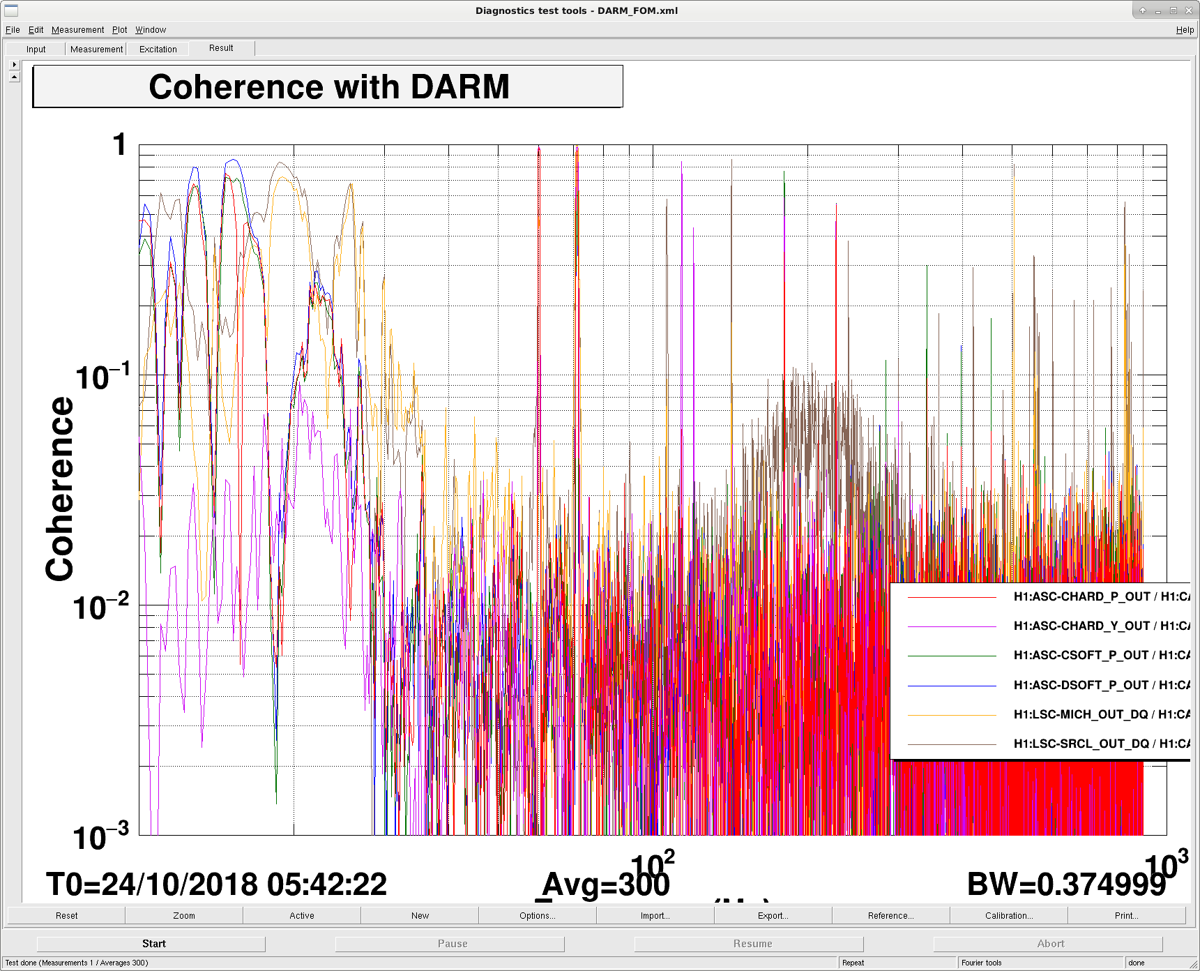
However, coherence is very poor between DARM and PDA/PDB, even when the noise is high.
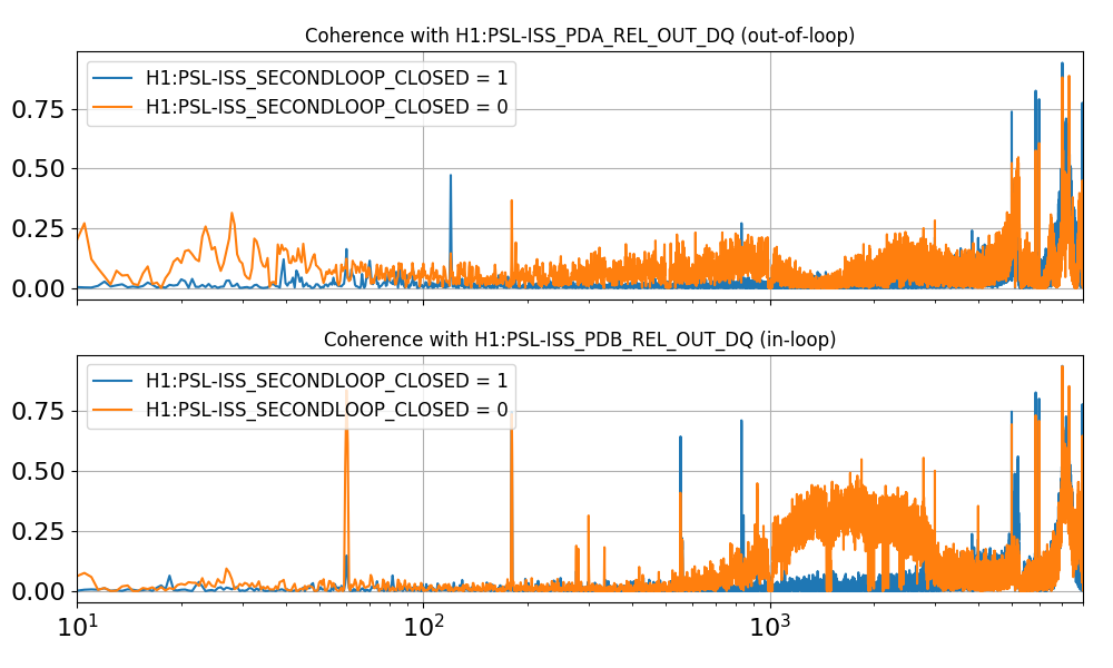
It's however clear that the noise increase in DARM is related to toggling the ISS input switch (we tried many times).
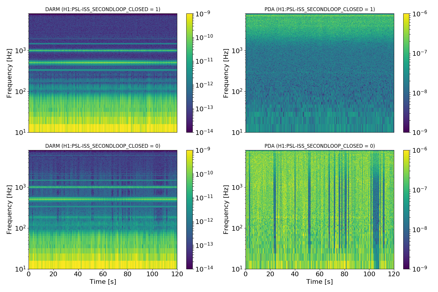
Spectrograms of DARM and PDA (out-of-loop signal) in the quiet and noisy periods show that the noise is highly non stationary, so maybe this is enough to explain the lack of coherence.
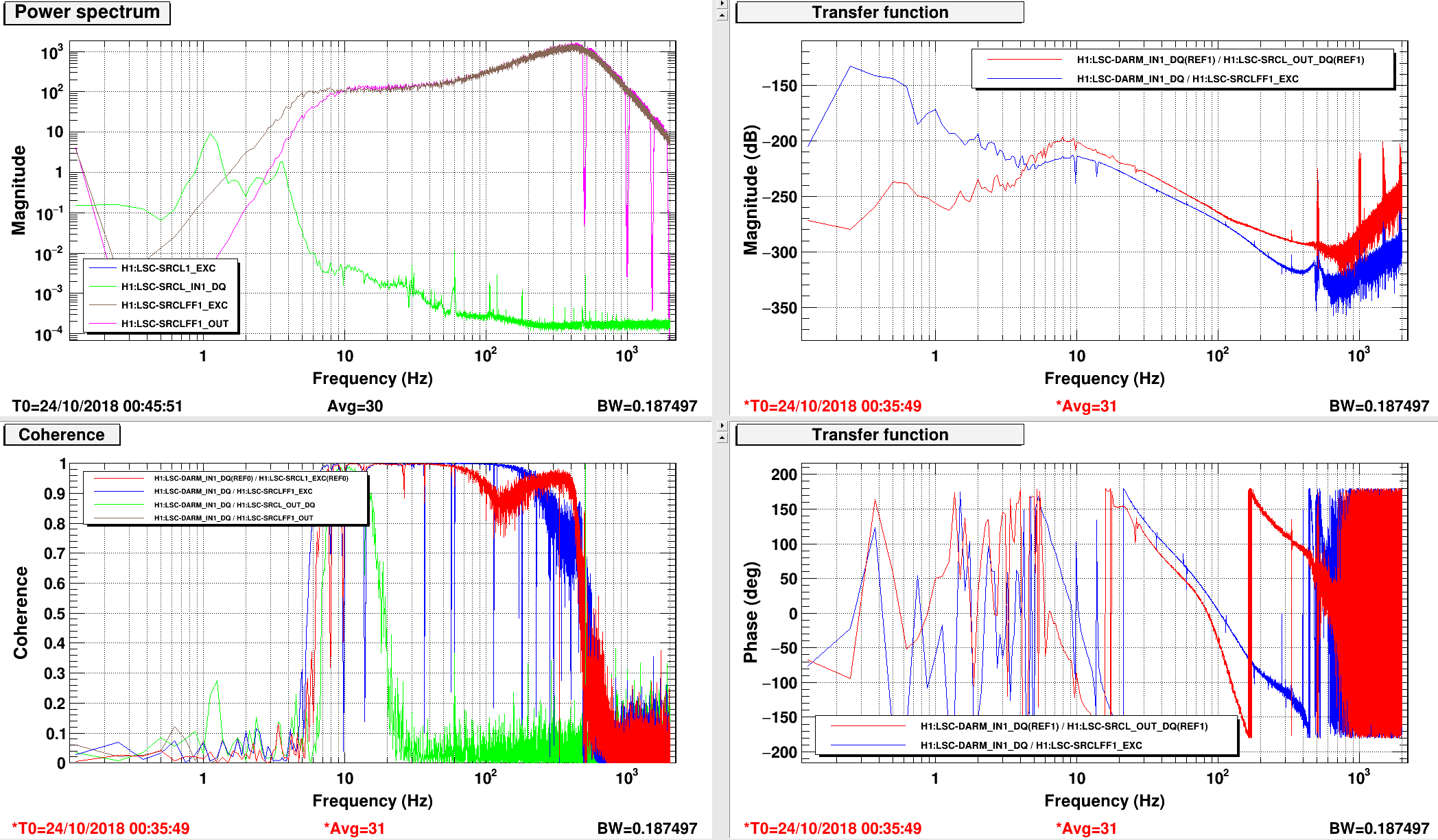
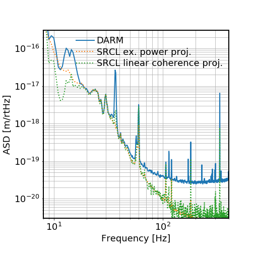
So the next question is how close is the intensity noise (as measured by the ISS first loop out-of-loop signal) to limiting us in normal condition?
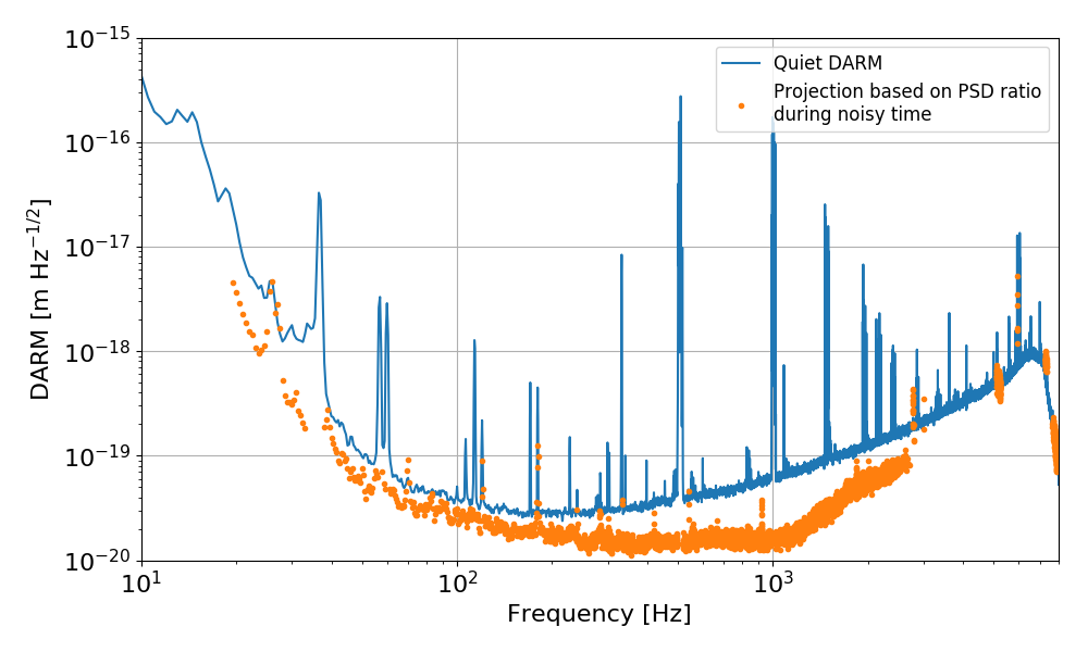
To answer, we computed the ratio of the DARM spectrum over the PDA spectrum while in the noisy state, and use this ratio to project the quiet state PDA spectrum into DARM. We restricted the projection to only those points where the DARM noise got higher by more than a factor of two when in the noisy state. The result, shown below, seems to indicate that we are likely limited by "intensity" noise measured by the ISS first loop sensor, which couples in a non-stationary or non-linear way, so we don't see coherence.
Next steps:
- understand why the noise in the first loop signals got worse with that switch open (maybe a dangling connection?)
- understand if the noise at that input is limiting the ISS first loop performance even when the ISS second loop switch is closed
- check if other PSL signals got worse (frequency noise?)
- do some intensity noise injections, to make sure we see the same with "real" intensity noise
More information:
- when the ISS second loop switch is open (noisy state), we see a clear increase of intensity noise in the ISS second loop signal, which is coherent with DARM
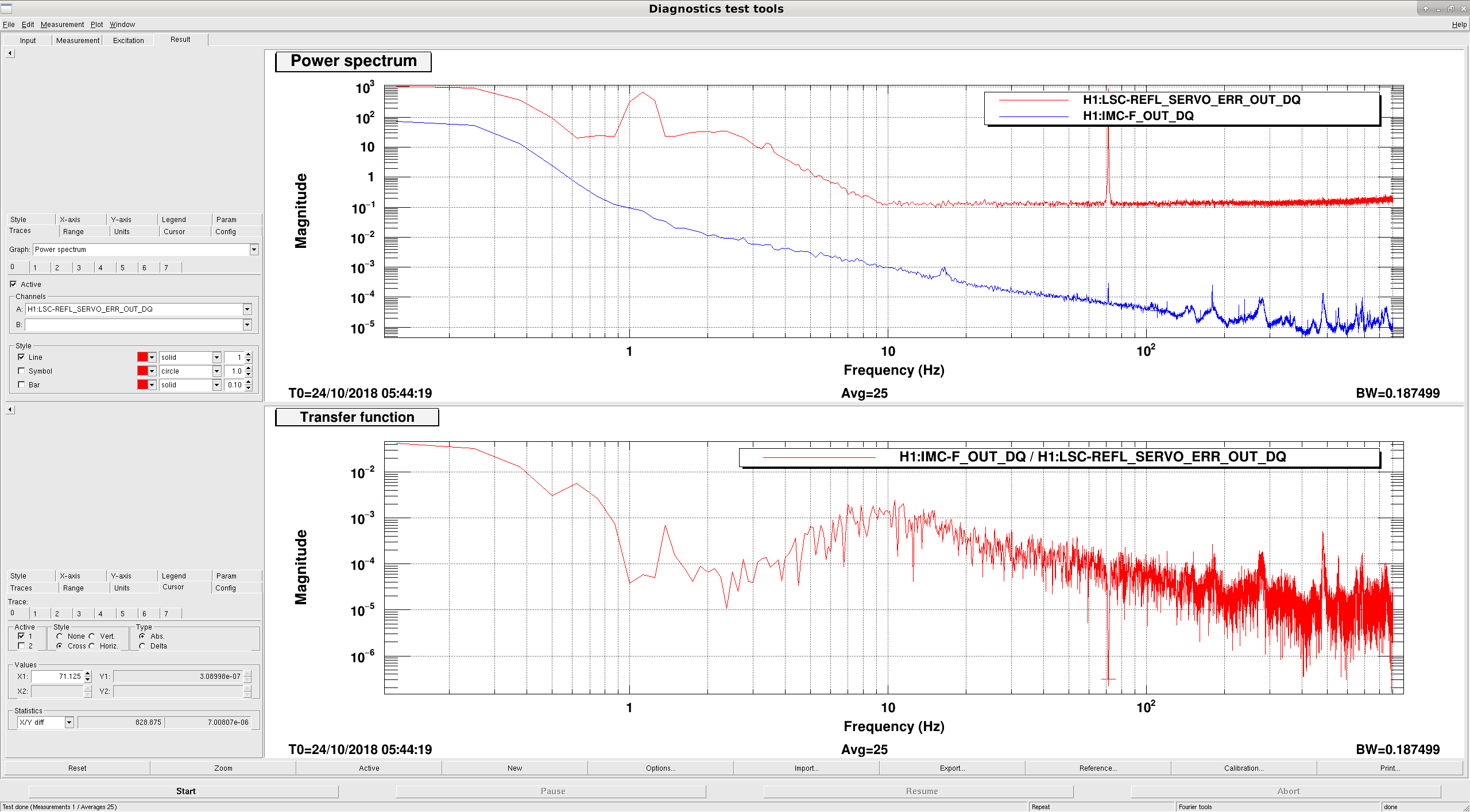
- there is also an increase of "frequency noise", at least as seen by REFL SERVO signals.