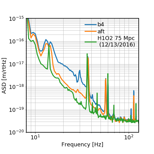
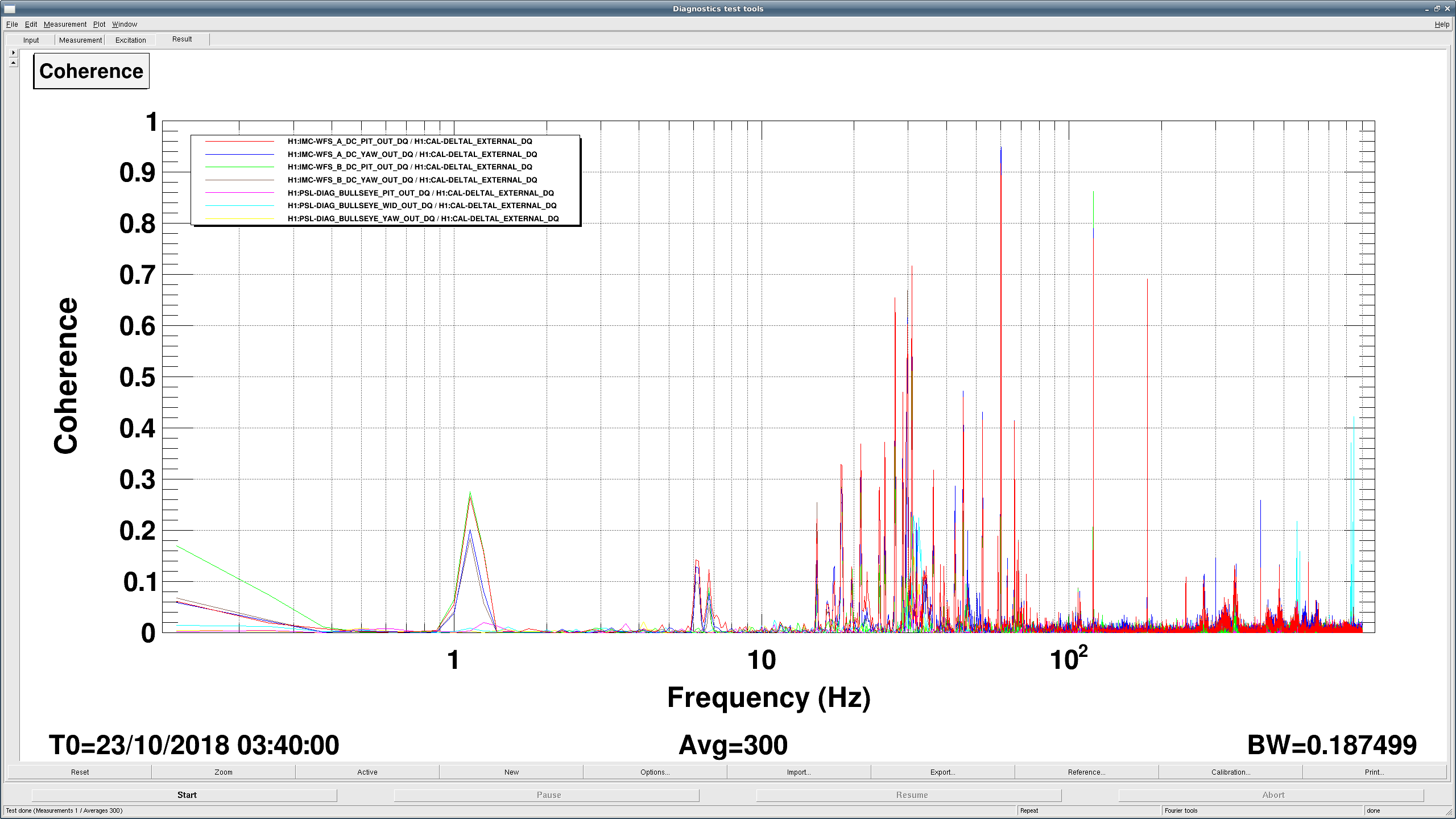
I reduced the 9MHz modulation depth by 6dB, and it seems like that gives us several more Mpc. It seems like our sensitivity is really improving when I reduce the modulation depth, although I'm not sure why it has such a significant effect, particularly at high frequencies. I plot here also 3 of the calibration lines, so you can see that their peaks are lining up pretty well. If anything, the green and brown traces with the 9MHz at it's lock acquisition value are a bit worse than they look here, since the 1080Hz line should be scaled up by a teeny bit.
Note that the lockloss around 16:45 was me, trying to reduce the 9MHz by another 3dB, but the old script that I use to step by hand further didn't include compensation for the analog CARM gain. I've fixed the script, so will likely try again next lock.

I have now put the 9MHz reduction into the main acquisition sequence path.
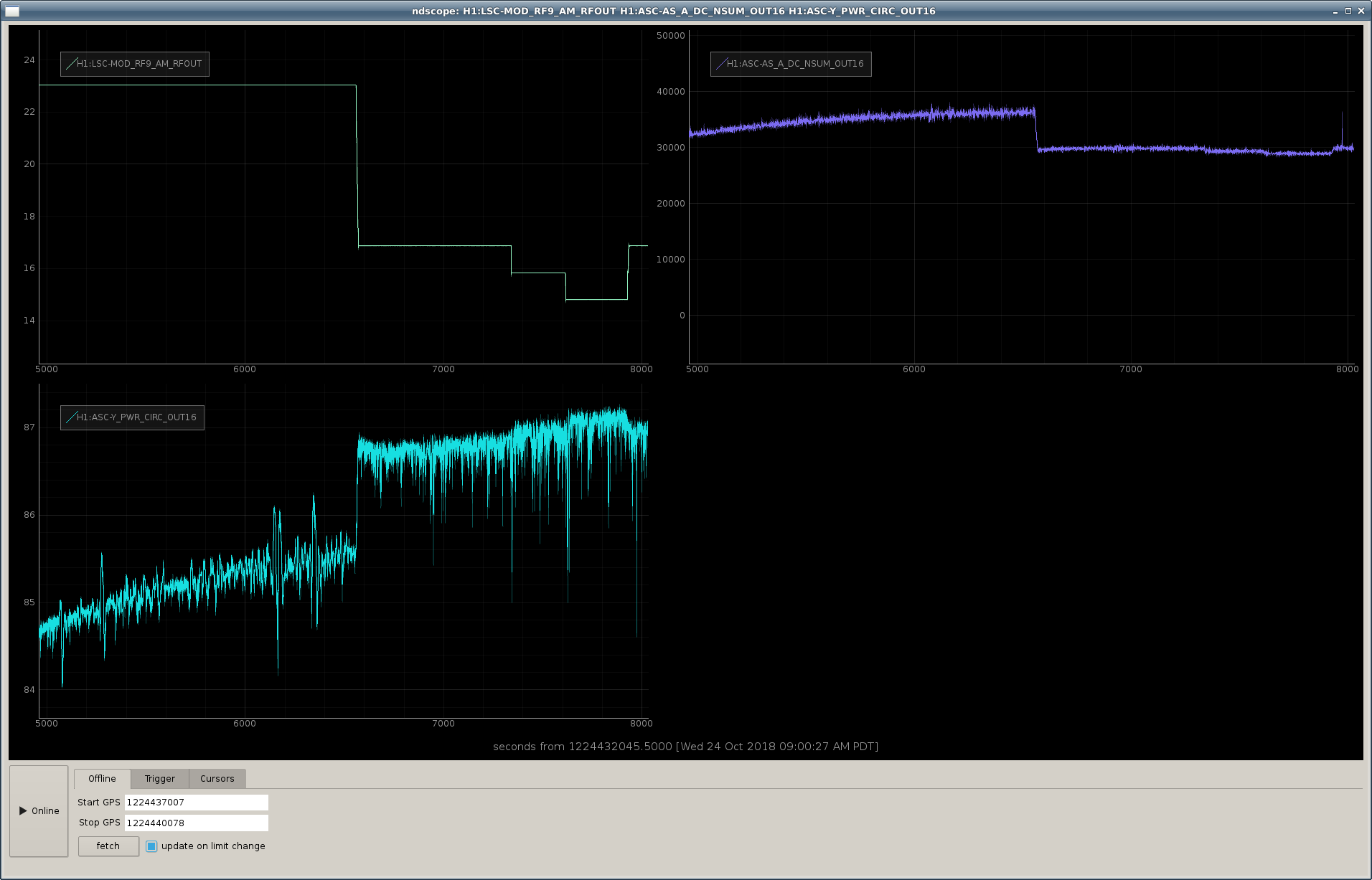
The attached plot shows that we are really seeing more power circulating in the arm cavities (and also less power at the AS port) when the 9MHz modulation depth is reduced. So, there must be some offset somewhere that we're reducing.
Also, I tried reducing the modulation depth by 8dB rather than just 6dB, and the IFO gets noticeably more glitchy when I do the extra 2dB. So, it seems like 6dB of reduction is a reasonable place, and we can work on finding what is causing this circulating power change.
Since we're reducing the 9MHz modulation depth from 0.2ish to 0.1, we're changing the 9MHz power from 4% to 1%, so should have ~3% more carrier power. That is consistent with the increase in circulating power that we see. However, the apparent shot noise reduction implies a much larger increase in power, so something is still not quite hanging together.
It would be worth checking the RF levels on the other LSC RFPDs used for LSC control (if you haven't already), as was done yesterday for REFL9.
Premature to say we're gaining something, as I don't see the same reduction in uncalibrated DARM nor in OMC DCPD.
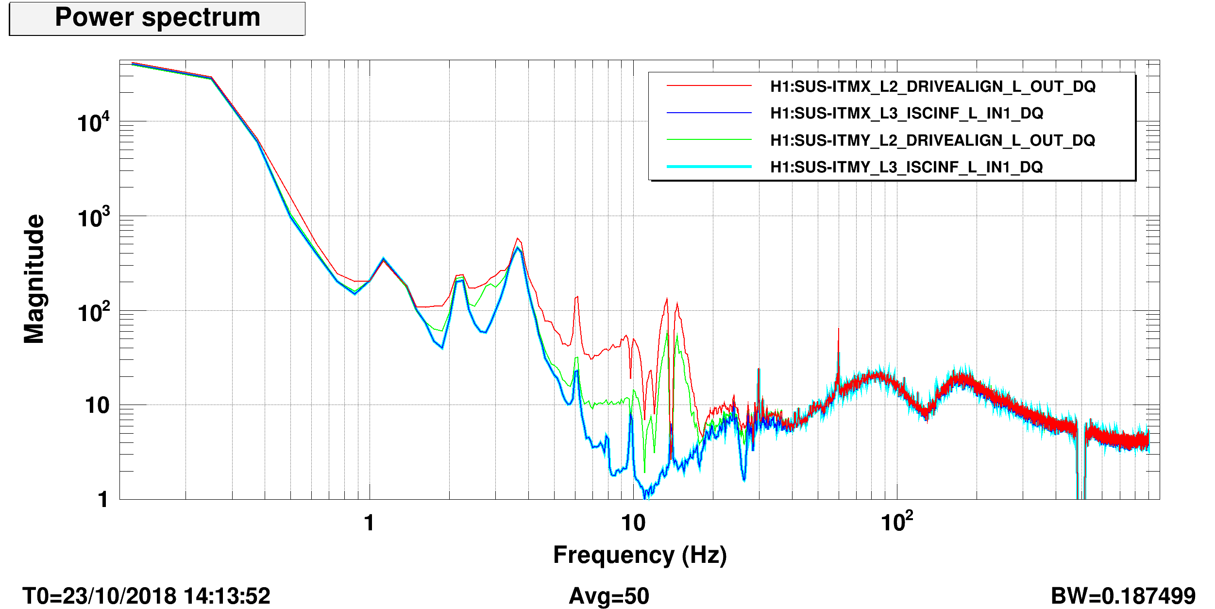
In the first attachment , red, blue and brown are from the single lock stretch corresponding to Jenne's red, blue and brown. No improvement at 1kHz at all, and the frequency noise part (f>2k or so) is worse when 9MHz was reduced. In Jenne's plot the improvement was pretty much 15 % or so over the large frequency region.
The second attachment is later in the morning. Blue is small RF9, green is large RF9.
In the latter there seem to be a difference at 100Hz but I don't know if this was due to high/low RF9 mod index.
Optical gain difference between high/low RF9 was no larger than a few % in both of the lock stretches.


Update (Jenne, Keita): Things makes more sense now.
In the attached, you should compare red (reduced RF9) with brown (not reduced) from the same lock stretch, or blue (not reduced) with pink (reduced) from another lock stretch. Legends are in UTC. In both of the cases, smaller modulation index increases the frequency noise in high kHz but seems to somewhat reduce noise at 100Hz.
It didn't make sense at first because there was an error in the legend of Jenne's plot.
Details:
Turns out that the legend for the brown trace (15:59:07, 9MHz back to normal) in Jenne's plot was incorrect, it was neither UTC nor local time, it was actually from 09:53:02 UTC, i.e yesterday. This means that all of her "9MHz reduced" traces are from today and all of "9MHz normal" traces are from yesterday.
But she intended to look at 15:59:07 UTC for brown trace, which was from today when 9MHz was reduced (but the CM gain setting was not changed to compensate). In the attached, red and brown are the same as Jenne's red and what Jenne intended to show in brown, these are from the same lock stretch.
Blue and pink are from another lock stretch later in the morning. (In this case, CM gain setting was changed to compensate for the optical gain.)
Low RF makes frequency noise worse at high-kHz due to lower S/N (pink VS blue). In the case of red VS brown, overall CM gain was lower, making the difference larger than pink VS blue.
To confuse the matter further, somehow at some point in yesterday the shot noise level seemed to have improved according to Sheila, and that is clearly seen in green trace from yesterday.

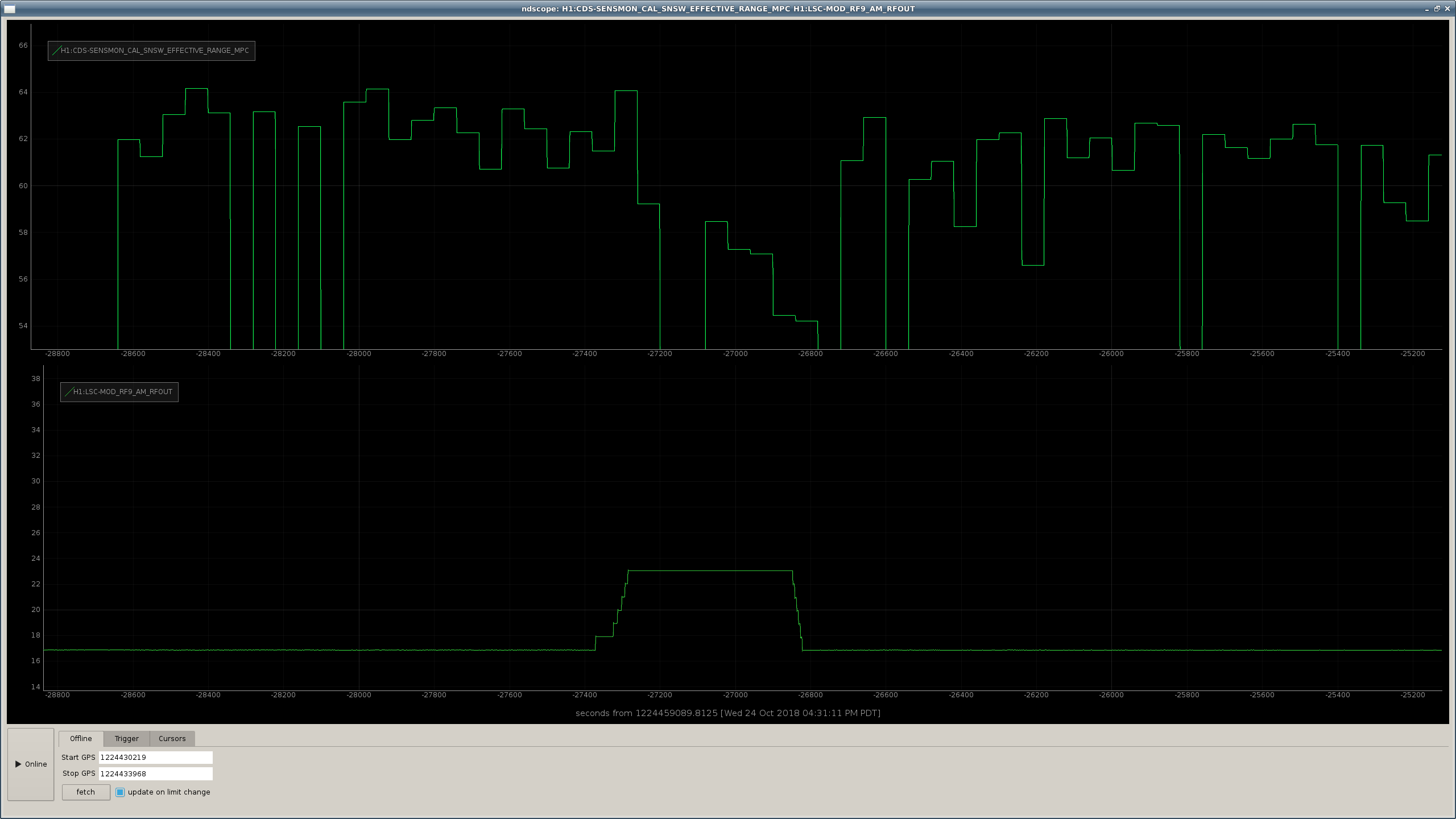
There is at least a bit of a change in the range during the on/off test that I meant to plot the times of from this morning. See attached.
I've modified EvanH's old stepping modulation depth script so that it will change the modulation depth, wait 10 min, then change it back, repeating 5 times. If the IFO is locked when the last person leaves for the night, please launch this (attached, and in /ligo/home/jenne.driggers/LHO_work/2018_10_24_9MHz_reduction/step_9MHz_many.py)

I modified Jenne's modification of step9.py so that the user can CTRL+C the skip at any point and the PD gains will all be returned to their original values when the script starting running.  Useful for when we lose lock during the test.

Pressing Ctrl+C while the gains are changed and the interferometer is locked is not recommended: the script will instantaneously return all gains to original values.

Code lives in:
/ligo/home/craig.cahillane/utils/step9mod.py

Started a run of this code at Oct 25 2018 09:52:44 UTC (1224496382).
Yet another update:
For the moment I take back my statement about lower modulation index VS high kHz frequency noise, the coupling itself is slowly changing with time and I might have been tricked.