Displaying reports 45001-45020 of 84887.Go to page Start 2247 2248 2249 2250 2251 2252 2253 2254 2255 End
Reports until 10:08, Friday 16 March 2018
H1 SUS (CDS, ISC, SQZ, SUS)
jeffrey.kissel@LIGO.ORG - posted 10:08, Friday 16 March 2018 (41032)
Understanding H1SUSOPO TFs with Modeling and Comparison with L1SUSOPO: Progress, but Not Enough
S. Aston, Á. Fernández-Galiana, J. Kissel, M. Pirello, T. Shaffer

We're still struggling for understanding as to why the H1SUSOPO suspension transfer functions looks like garbage in so many confusing ways. 

The message: we're getting closer, but it still doesn't make complete sense -- which means we still can't damp the suspension -- which means we can't just "close it up" 'cause it's "good enough."

Details below.

Attached are an annotated set of .pdfs that summarize the current state of knowledge.

ANNOTATION LEGEND

BLUE / RED: 
Stuff with which I’m happy, and I think we should just update the old model.
	- Increased the length of the wires from 146 mm to 155 mm. This was an honest mistake in not accounting for the distance between the bottom of the wire clamp and the actual suspension break off point:
         % See Wire Assembly D1500483-v3 and
         % Wire Pulling Jig Assembly D1500481-v1
         % [[D1500485-v2 (0.25in + 1.5in) + D1600451-v2 (3.983in) + D1600462-v1 2*(0.18in) = 6.093 in = 154.76 mm]]
         % (was 145.61, but forgot the extra thickness to the *actual* suspension point i.e. the 2*0.18in from D1600462)
		> This dead reckoned number then immediately better matched the L, T, and Y 
		  primary resonances without further tweaking needed.

	- Increased the blades’ Young’s modulus by only 11% to better match the primary V frequency.

	- (The mass remains at 36 kg).

	- Updated diagonal MoI’s, Ixx, Iyy, Izz (corresponding to R, P, and Y, respectively) 
	  to better match measured primary R, P and Y frequencies.
		> started with Álvaro’s updated Solidworks numbers, and only had to tweak the numbers ~5%.

	- Broke out the damping matrix into a value for each DOF (but still a diagonal matrix)
		> Used to be all 1.0. Now (L, T, V, R, P, Y) = (0.3, 0.3, 3, 0.03, 0.06, 0.1).
		> This nailed the Qs of the primary resonances, and therefore automatically got most of the cross-coupling right.

	- Added off-diagonal MoI’s to the parameter file and model. 
		> Essential to explaining the third resonance in the R and P transfer functions.
		> had to do a lot of playing here, but good enough for government work. 
		> Ixy = 30% lower, Ixz = factor of 10 higher, Iyz = factor of 100 higher.

GREEN: 
Unexpected, yet measured, cross-coupling + dubious modeling with which I’m guessing and would love insight.  The few physical mechanism I can imagine, but only guess how to model:
	- V to Y coupling, or a “corkscrewing”. This, I’d imagined was a sensor or actuator flaw, like the V OSEMs sensing/driving at some angle to the vertical axis. A little implausible, because they’d have to all be cocked in the same direction. I modeled this by adding a V to Y component to the stiffness matrix, but I have now idea how one should really do it.
	- T to Y coupling. Here, the mechanism I imagine is a little more plausible: a ~5 mm offset from the transverse actuation plane (TAP) and the horizontal CoM would create a yaw torque. I’m a little more confident in adding that term to the stiffness matrix, because it’s a similar effect to what Álvaro already has in the model to create the “standard” (Longitudinal to Pitch) and (Transverse to Roll) coupling. BUT — if that TAP offset exists, there’s no reason to think an LAP doesn’t exist. 

ORANGE / PURPLE: 
Stuff I still have no clue how to explain.


THINGS WE'VE RULED OUT IN HARDWARE

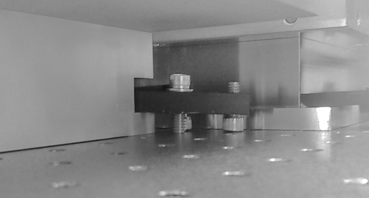
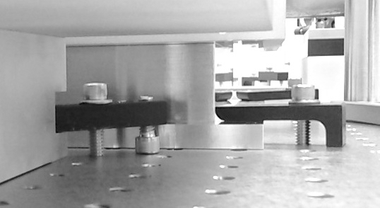
     - TJ promises that the H1SUSOPO is not rubbing, but continues to question whether he can really tell given the poor visibility and tight quarters in chamber. I've told him to hold off checking again until we can get the HAM6 ISI balanced, floating and damped. That might at least get rid of some of the incoherent noise.

     - TJ, Alvaro, and myself have all gone over the OSEM2EUL and EUL2OSEM basis transformation matrix math, and it all seems to check out. See the "other files" of G1701821.

     - After consulting with the analog CDS team project-wide, we identified that the OPOS is the last hold-out using -v2 of the HAM-A coil driver D1100117, which has lower output impedance, and thus increasing the transconductance from v3 by a factor of 10. Every other SUS that uses the HAM-A driver (HAUX and HTTS) have had their impedance increased, as per ECR E1201027. This explains some of the discrepancy between the model L1's measurement, but it doesn't explain why H1 is all over the map.

     - Hearing this, (and remembering the jumper issues with ZM2, LHO aLOG 40218, and ZM1 LHO aLOG 40241), I was suspicious we were driving one-third of the SUS with v2 and two thirds with v3. Even though the chassis were clearly labeled when we got to the racks, Marc was gracious enough to open up the OPOS HAM-A coil drivers so we could see with our own eyes that the output impedance on R33 and R11 were 100 Ohms as expected.

ANALYSIS DOCUMENTATION 
Also attached is the model ssmake_voposus.m and RED parameter set, oposopt_h1susopo_fit.m which produced to today's results, which will become obsolete after we merge the stuff we like with the BLUE parameter set oposopt_h1susopo.m, which we'll probably rename to something like oposopt_production once we're happy.

Just to record everything I've been using:
${SusSVN}/sus/trunk/Common/MatlabTools/SingleModel_Production/
    comparesingleparams.m    << comparison script

    ssmake_voposus.m         << dynamical model

    oposopt_h1susopo.m       << BLUE reference parameter
    oposopt_h1susopo_fit.m   << RED updated parameter set

${SusSVN}/sus/trunk/OPOS/L1/OPO/SAGM1/Results/2018-01-29_0900_L1SUSOPO_M1.mat
${SusSVN}/sus/trunk/OPOS/H1/OPO/SAGM1/Results/2018-02-27_2209_H1SUSOPO_M1.mat

*phew* this is exhausting.
Non-image files attached to this report
H1 SEI
hugh.radkins@LIGO.ORG - posted 19:50, Thursday 15 March 2018 (41031)
WHAM6 ISI Unlocked and Balanced. Left unlocked & floating with C3 Covers pulled away--purge is pretty strong though

w/ unwavering support and patience from Corey, we got the table floated and balanced, finally.  Added a loooot of weight to get it.  Will detail things in an additional alog tomorrow.

H1 PSL
jason.oberling@LIGO.ORG - posted 17:31, Thursday 15 March 2018 (41028)
PSL 70W Amplifier Installation Update #7

J. Oberling, C. Vorvick, E. Merilh, P. King, J. Bartlett

Mode matching, mode matching, and more mode matching.  We began Monday by installing the mode matching solution detailed in the previous alog, and then attempting to optimize it to get close to the desired waist for the 70W amp.  Unfortunately, as is the case with most 1st attempts at mode matching, this didn't get us where we needed to be; the smallest we could get the beam was ~450 µm in diameter, a bit off of the required 273 µm diameter.  At this point, Cheryl volunteered to lend us her experience in mode matching, which I accepted (thank you Cheryl!).  So on Tuesday morning, Cheryl and I went into the enclosure to tweak up the mode matching.  She took accurate measurements of the lens positions and we re-measured the waist; in addition we looked at the previous measurement Ed and I took of the FE beam to assess beam quality (done with the Wincam), and we took a new one with the Thorlabs beam profiler after the mode matching lenses (1st attachment).  As them beam looked like it had some lobes on it (which was not different than the older Wincam image), we then looked at the beam path from the NPRO to the MOPA inside the 35W FE to see if there was anything that could be causing it.  We found that the beam alignment through the extra AOM inside the FE was off, as well as some very slight clipping on the razor blade dump meant to block the 1st order diffraction from said AOM (if it was being utilized, which it is not).  We also took a look at the beam profile of the NPRO using the Thorlabs beam profiler (2nd attachment), and didn't see anything that looked amiss.  We decided to move on with optimizing the mode matching, so Cheryl took the lens position and waist measurements and plugged them into A La Mode (Matlab mode matching script), which told us how to move the mode matching lenses to optimize the output waist.  We went back and forth with this for a while, getting closer, but not quite getting there.  One problem we immediately noticed: the downward angle of the FE beam induced by the new pick-off was causing us problems with the lens alignment.  We did not have enough adjustment range on the Owis lens mounts to center the lenses on the beam, and since these mounts were originally installed on fixed-height pedestals, the small amount of adjustment range from the mount was all we had.  We decided to call it a day and continue on Wednesday morning.  That evening, Cheryl dug into A La Mode to work on a robust mode matching solution.  Her results were to use the same lenses (f1 = -50mm, f2 = 80mm), but move the position to +479.5mm for the 1st lens and +527.7mm for the 2nd lens (this assumes 0.0 mm is the outside edge of the 35W FE enclosure).

First things first on Wednesday, we had to decide what to do about the lens alignment problem.  In an ideal scenario (assuming we had all the time in the world), we would painstakingly align the beam out of the FE to correct for the downward beam angle.  Back in the real world however, we decided to ditch the fixed height pedestals for adjustable height.  Due to the odd mounting of the Newport SDS40 translation stages, we had to ditch these as well.  Eventually, we were able to come up with a workable solution that gave us the adjustments we needed to complete the mode matching; unfortunately, this took most of the day.  While I was building out the new mounts, Cheryl painstakingly measured the distances to position the lenses and made fiducial marks on the table.  Once the new mounts were assembled (3rd and 4th attachments), we test fit them on the table; the footprints are larger than the old fixed-height pedestals, but they fit where they need to and give us the adjustment we need.  We have since found (see below) that we probably need to swap out the huge micrometer on the 2nd lens mount with a smaller one, but for now this gave us a workable solution.

On Thursday, Ed and I began fixing the above noted clipping issues in the FE.  We removed the side panel and adjusted the AOM position so it was centered on the beam.  We then moved the beam dump just enough to clear the slight clipping.  Of course, upon turning the MOPA on, we had to slightly adjust the alignment into it to return to optimum operation.  We checked the beam alignment outside of the FE and everything looked to be in the same place, so we moved onto installing the mode matching lenses.  We started by installing and aligning the new lens mounts; we took care to ensure the mounts were even and aligned to the beam.  We then installed the lenses, aligning after each install.  After this, we set up the Thorlabs profiler and began adjusting the position of the 2nd lens.  Right off the bat we had a waist of ~344 µm in diameter (5th attachment).  Moving the 1st lens a small bit and readjusting the 2nd, I was unable to get the beam any smaller (moving both directions for the 1st lens produced the same results, a larger beam at our desired waist location).  Cheryl had joined us by this time, and we decided that this was close enough for a rough mode match (we'll optimize the mode matching once we have the 70W amplifier installed and aligned), so we started placing the other required optics in the beam path: WP02, PBS02, AMP_WP02, AMP_FI (and associated beam dumps), AMP_WP03, and AMP_M01. 

We immediately ran into a problem.  Due to an interference between M04 and M33 on the original PSL layout (that oddly enough was not present at LLO, per M. Heintze), the beam out of the LHO FE was not aligned along the row of holes as indicated in the layout; it was angled towards the FE slightly.  Because of this, the mount for WP02 (which assumes the beam is aligned along a row of holes), is clipping the beam.  At this point I had to leave to attend a meeting, so Cheryl and Ed finished up installing the table components.  The WP02 issue was resolved by changing the mount to a fixed height post and a baseplate.  They put the Faraday isolator (AMP_FI) on the table and noticed immediately that the beam was clipping (once again being bit by the downward launch angle imparted on the beam by the new FE pick-off).  They re-installed the dog leg after M33 so the beam height could be adjusted up and made level through AMP_FI.  The final attachment shows this setup; this is simply a mock up, as M09 and M10 are to be used in the FE DBB path, and they had to shift AMP_FI laterally, which blocks the beam from the 70W amplifier.  Unfortunately, given the huge micrometer on the 2nd lens mount, this is the only way to currently install this setup.  So first thing tomorrow we need to hunt down a smaller micrometer for the 2nd lens mount, so the dog leg can be shifted up the table to clear the interference between AMP_FI and the resulting 70W amplifier output beam.

While all this has been going on, Peter has been working on figuring out the wiring for the new external shutter so that is ready for when we have light through the 70W amplifier.  Jeff Bartlett has been working on the plumbing required to get the power meter in the new external shutter plumbed into the PSL cooling loops; this power meter will use the old HPO power meter circuit.  In addition to this, Peter and Jeff dried out the old HPO Laser Head and Laser Crystal water circuits; once the new external shutter power meter has been plumbed in, the HPO Power Meter water circuit will be dried out as well, thus completing the mothball of the HPO.

Images attached to this report
H1 ISC (ISC)
marc.pirello@LIGO.ORG - posted 16:07, Thursday 15 March 2018 (41022)
Scan PopAir B 90 Mhz for faults with VNA

Scanned the 90MHz patch cables and Heliax cable for faults with the Agilent Vector Network Analyzer (VNA) set to Distance to Fault (DTF) mode.  The scan originating at the CER was clean with one suspicions marker near the 20m mark.  The scan originating at the PSL did not record this marker, and was much noisier.  We suspect this final patch cable between the patch panel, and the I/Q Demod is damaged and needs to be replaced.

After further review, the Balun was causing problems with the VNA.  Upon removal of the Balun the plot started to look what it should look like.  There is still a suspicious blip at 18.4m from the CER patch panel, but the blip is less of a disturbance than a connector.

WP7419

FRS6599


Non-image files attached to this report
H1 General
jeffrey.bartlett@LIGO.ORG - posted 16:02, Thursday 15 March 2018 (41026)
Ops Day Shift Summary
Ops Shift Log: 03/15/2018, Day Shift 15:00 – 23:00 (08:00 - 16:00) Time - UTC (PT)
State of H1: Unlocked for maintenance and upgrades
Intent Bit: Engineering
Support: X
Incoming Operator: N/A
Shift Summary: Maintenance and upgrade work continues apace across the site.    
 
Activity Log: Time - UTC (PT)
15:00 (08:00) Start of Shift
15:06 (08:06) Terry – Going into LVEA to work on Squeezer
15:14 (08:14) Vanessa – Going into the LVEA for cleaning
15:58 (08:58) Hugh & Betsy – Going to HAM6 to talk to Squeezer folks
16:06 (09:06) TJ – Going to HAM6
16:12 (09:12) Jason & Ed – Going into PSL Enclosure to work on 70W alignment
16:26 (09:26) Gerardo – Into the LVEA looking for a septum cover
16:34 (09:24) Hugh & Corey – Unlocking and balancing HAM6 tables
16:45 (09:45) Jeff K. – Going to HAM6 area
16:45 (09:45) Gerardo – Out of the LVEA
16:46 (09:46) TJ – Out of the LVEA
16:46 (09:46) Marc – Going to CER and PSL rack (WP #7419)
16:47 (09:47) Nutsinee – Going to HAM6 area
17:04 (10:04) Pepsi on site to service vending machines
17:06 (10:06) Nutsinee – Out of the LVEA
17:10 (10:10) Peter & Arijit – Peter escorting Arijit into PSL Enclosure
17:32 (10:32) Filiberto – Into LVEA and Mechanical building cabling for TCS Beckhoff
17:50 (10:50) Dave – Going to H2 Electronics building
18:00 (11:00) Marc – Out of the LVEA
18:15 (11:15) Georgia – Turning on TCS- X and TCS-Y Lasers
18:22 (11:22) Richard – Going to HAM6 to talk with Hugh
18:26 (11:26) Karen – Cleaning in the H2 building
18:40 (11:40) Peter & Arijit – Out of the PSL Enclosure
18:47 (11:47) Jason & Ed – Out of the PSL Enclosure
19:01 (12:01) Karen – Out of the H2 building
19:20 (12:20) Elizabeth – Going to both mid and end stations to work on network switches
20:54 (13:54) Elizabeth – Back from mid and end stations
20:58 (13:58) Greg – Going to work on TCS-X laser table
21:00 (14:00) Jason & Ed – Into the PSL Enclosure for mode matching work
21:00 (14:00) Cheryl – Going into the PSL Enclosure to modify ISS dog clamps (WP #7421)
21:08 (14:08) Betsy – Going into the LVEA to look for parts
21:30 (14:30) Betsy – Out of the LVEA
21:40 (14:40) Marc – Back into LVEA to work on RF90 cable
21:57 (14:57) Jason – Out of the PSL Enclosure
22:00 (15:00) End-Y being transitioned to laser hazard
22:08 (15:08) Lockout/Tagout lock in Bubba’s name on End-Y PCal laser. Spoke with Bubba – He gave verbal permission for the PCal crew to remove his lock. Notified Darkhan by phone of same.
22:21 (15:21) End-Y has been returned to laser safe. Lockout/Tagout has been restored to its original condition.
22:40 (15:40) PCal crew back from End-Y
22:55 (15:55) Jeff K. – Out to talk with HAM6 SEI crew
23:00 (16:00) End of Shift
   
H1 CAL (CAL)
darkhan.tuyenbayev@LIGO.ORG - posted 15:47, Thursday 15 March 2018 (41025)
PCALY beam alignment check

Niko, Darkhan,

We checked the alignment of the Pcal beams at EY by looking at the beam positions at the RxPD integrating sphere input port (in the Pcal receiver module). As was expected, the beams are well centered on the port.

Note: To do this check we needed to temporary turn on the Pcal laser (for which we removed the lock from the module with Bubba's permission). After the work was completed we switched off the laser and put Bubba's lock back on the Pcal AOM and laser power supply module.

Images attached to this report
LHO VE
kyle.ryan@LIGO.ORG - posted 15:06, Thursday 15 March 2018 (41024)
CP4 Regeneration update
Today I lifted the three heater element wires from the terminal strip located within the Regeneration Control Panel and used a "High Potential" tester to apply 1000 volts between each wire and ground.  I varied the current limiter throughout its range (0.3mA - 12mA) while the high voltage was being applied and did not detect a short to ground - good!  Next, I terminated the 4-20mA CDS wires on to the SCR unit and energized the Regeneration Control Panel - no faults.  Finally, and without any GN2 flow, I enabled the CDS PID control with a setpoint of 50C and proportional gain of 7.  The Regeneration Temperature rose -> 24.1C,  24.2C, 24.3C, 24.4C, 24.5C - over the course of 5 minutes or so before the control panel tripped with a "HIGH LIMIT" fault.  This is as expected considering the absence of GN2 flow to remove the heat from the heating elelments.  The thermocouple used for the "HIGH LIMIT" is in contact with the heating elements ballast mass while the thermocouple used for the PID control "Regeneration Temperaure" is several inches downstream of the heating elements and it samples the GN2 flow.  

So, it looks like the Regeneration Control Panel is working again (for the time being!).  We are installing a second in-duct cartridge heater tomorrow and will have to shut down the forced-air heating unit so maybe Monday we can try to start up the regeneration flow again and start dumping some Joules into that CP4 bad boy!
LHO VE (VE)
david.barker@LIGO.ORG - posted 14:17, Thursday 15 March 2018 - last comment - 16:03, Thursday 15 March 2018(41023)
bypassing CP4 REGEN Interlock alarm until Monday

Kyle confirmed that the CP4 regen overtemp interlock alarm will be in the alarm state from now through Monday. I have bypassed this channel from sending cell phone texts until that time. Email alerts for this alarm will continue to be sent.

Comments related to this report
david.barker@LIGO.ORG - 16:03, Thursday 15 March 2018 (41027)

CP4 TE253A, which is currently following the ambient temperature (with ROC alarm levels of +/-5.0 degC per Hour) generated an alarm earlier today when the outside temperature increased at 5.5 degC/hr for a short period of time (when the Sun came out possibly). If this becomes a nuisance we can consider raising the alarm levels.

H1 General
jeffrey.bartlett@LIGO.ORG - posted 13:30, Thursday 15 March 2018 (41021)
13:00 Vent Meeting Minutes
PSL:
Closing in on mode matching alignment
Next up - connecting the 70W laser
 
HAM6:
SEI crew unlocking and balancing the HAM6 table
Squeezer work continues
Commissioning of the VOPO is working through several issues
 
VAC:
Installed a new NEG pump at End-Y
End-Y door is on
There is additional vacuum work to complete before pump down can start
 
End-X:
PCal periscope alignment
Prep work for Quad LS extraction
 
CDS:
Working on replacing suspect POP RF90 cable
Connecting TCS Chillers to RS232
 
Tuesday Maintenance:
Video cameras for HAM6/Squeezer
ISI model reboot  
H1 PSL (PSL)
cheryl.vorvick@LIGO.ORG - posted 21:35, Wednesday 14 March 2018 (41019)
PMC dog clamp rework complete, one more to add if access becomes possible

I modified the one and only dog clamp on the PMC foot on the NW corner, from angling up toward the contact point with the PMC foot, to angling down.  Should the ISS box need to be removed, a second dog clamp on the NW foot would be advised.  There is room at the table level, but not for both tools and hands between the ISS box and the PMC while both are installed.

Previous changes to dog clamps in alog 40822.

Images attached to this report
H1 IOO (IOO, PSL)
cheryl.vorvick@LIGO.ORG - posted 21:08, Wednesday 14 March 2018 (41018)
GigE camera install on the PSL table

I removed my O2 GigE camera installation, and have moved the cameras to their O3 locations.  GigE camera 1 is now positioned to look at the beam coming out of the PMC, and GigE camera 2 is positioned to look at the transmitted beam of the bottom pericope mirror.  Both are blocked by beam dumps until the beam is restored for alignment.

I rerouted the AOM RF cables that were curved to go around the high power beam dump, to go in front of the high power beam dump.  Attached pictures show 2013, the original install, and today, which shows the cable with only one curve, from the connectors to the table.  One the table, the cables are secured to prevent them from making contact with other components/bases, and to be as straight as possible.  Some cooling lines and other cables were also moved and re-secured.

Images attached to this report
H1 SQZ
daniel.sigg@LIGO.ORG - posted 18:39, Wednesday 14 March 2018 (41017)
OPO locked in-air

Nutsinee Terry Daniel

We were finally able to lock the OPO in air. We took the output of the common mode board and send it to the laser PZT via a Thorlabs PZT driver (gain of 15).  The ugf we achieved is 10kHz. With all 3 boosts engaged the lock is reasonably tight. The attached screenshot shows the CMB settings.

The noise spectrum indicates a strong acoustic peak around 1.1kHz that needs a large driving range.

We also measured the transfer function from the OPO PZT to the laser PZT. The first resonance is at ~6.0 kHz as expected—confirming that the 1.1kHz peak is not an inline resonance.

Some of the problems we encountered along the way:

Images attached to this report
LHO VE (VE)
gerardo.moreno@LIGO.ORG - posted 18:32, Wednesday 14 March 2018 (41016)
Y-End NEG Pump Installation

Installed a new type of NEG pump at BSC6 port C90G3.  Housing still needs a gauge.  Also, electronic/power components still need to be installed.

Images attached to this report
LHO VE
kyle.ryan@LIGO.ORG - posted 17:30, Wednesday 14 March 2018 - last comment - 17:37, Wednesday 14 March 2018(41014)
Replacement SCR also "shorted" after brief operation
Chandra R., Kyle R. 

Chandra attempted to re-establish heated GN2 flow through CP4's empty LN2 reservoir this morning (assists bake-out of CP4 currently in progress).  The original SCR had "shorted" after only days of use so we replaced it yesterday with one we removed from CP3's Regeneration Control Panel.  This time the SCR failed (shorted) after only minutes?  Tens of minutes?  

According to the SCR manual, this failure results whenever there is load current detected (sensing coil on one phase) in the absence of a 4-20mA control signal or when the load current is present and not a function of the 4-20mA control signal.  I investigated and found that the three delta-connected heating elements all measured 30 - 31 ohms between each other and Megaohms to ground, i.e. weren't shorted when the low voltage VOM output was applied.  I did not do a High Potential (HiPot) test.  Next, I lifted the CDS wires supplying the 4-20mA control signal and then energized the unit.  Still, even with the input removed, the SCR indicated an "SCR SHORTED" fault.  Long story short, all of my investigating suggested a shorted SCR vs. a problem in the associated external wiring.  

As such, I replaced this second SCR with a third one borrowed from CP5's Regeneration Control Panel and installed it.  This time, I did not land the CDS 4-20mA leads but, instead, left them "hanging".  I energized the Control Panel and did not experience the troublesome fault.  The Measured supply voltage was found to be 498 VAC which is quite high.  I recall that this is a known "feature" from "back in the day..." and seem to remember it was due do the Xformer tap that we use.  In any case, this shouldn't be an issue as the SCR is rated up to 600 VAC.  I also measured 9.4V between the 4-20mA control wires while not terminated.  Hmmmm... the CDS PID control is off.  Should there be voltage across these without a PID output?  

I'll try out this third SCR tomorrow and attempt to do so in small incremental outputs while monitoring as many pertinent metrics as possible.  If this third unit also shorts, we'll abandon the "dream" and concentrate on minimizing air leak losses to the room and adding more heat to CP4's insulated bake-out enclosure.  
Comments related to this report
kyle.ryan@LIGO.ORG - 17:37, Wednesday 14 March 2018 (41015)
Upon further consideration, two of the three phase currents get regulated by the SCR, the third phase does not.  Additionally, this unregulated phase is the one sampled by the sensing coil.  Hmmm... I'll definitely do a HIGH POTENTIAL test to make sure that there isn't a short to ground when hundreds of volts get applied.  This would explain the symptoms but seems far-fetched.  
H1 CDS
david.barker@LIGO.ORG - posted 16:57, Wednesday 14 March 2018 (41013)
vac alarms customized to tonight's operating conditions

Kyle, Dave:

to prevent nuisance cell phone alarms for out-of-nominal conditions overnight, we have reconfigured the alarms:

H0:VAC-MY_CP4_TE253A_REGEN_TEMP_DEGC is running cool, reduced its LOW alarm limit from 70C to 0C

H0:CDS-ROC_VAC_MY_CP4_TE253A_REGEN_TEMP_DEGC_1HOUR_R is trending towards ambient at a rate higher than 1.0 CperHour. Increase alarm rates to +/- 5.0CperHour

H0:VAC-MY_CP4_253_REGEN_TEMP_ALRM_INTLK will be in alarm overnight. Sends its alarms to emails only, not to cell phones.

H1 SUS
betsy.weaver@LIGO.ORG - posted 13:47, Tuesday 13 March 2018 - last comment - 10:32, Thursday 15 March 2018(40995)
ETMY BSC10 door closed

Today, I went in and pulled the 2nd First Contact sheet after the reapplication yesterday afternoon.  Unfortunately, the 2 small glint blemishes that I didn't like yesterday were still there.  So, they are either in the coating, scratches, or are not coming off.  So, I then completed the closeout steps of:

1) N2 blow, measuring charge (details below)

2) Placing the 1" witness optic on the side of the QUAD structure

3) Jim unlocking ISI

4) Placing 3" horizontal wafer below ETMY QUAD on floor

5) Mounting 3" vertical wafer on lower front of QUAD structure

6) Wiping the floor on the way out

7) Removing tools

8) Kissel running TFs - 3 per suspended chain - all good

9) Launching door crew

Door on by lunch, started work at ~9:30am.

Comments related to this report
betsy.weaver@LIGO.ORG - 10:32, Thursday 15 March 2018 (41020)

Details of the N2 deionization during this closeout:

Measuring at the back of the AERM surface, the measured voltage started at ~8v, measured in the Center, UL, LR positions.  We then pulled the FC and blew everywhere around the ETM and AERM for many minutes.  Measuring again, the charge at these locations was down to ~2.5v.  Another round of blowing, with a check of the zero of the meter in between, and the charge then read 1.3v in the Center and UL and 2.1v at the LR position.

5 minutes later we remeasured and found the charge at 0.4 in the center and -0.6v at UL.

H1 PSL
jason.oberling@LIGO.ORG - posted 16:50, Wednesday 07 March 2018 - last comment - 16:54, Thursday 15 March 2018(40886)
PSL 70W Amplifier Installation Update

J. Oberling, E. Merilh

The last few days have been spent taking caustic measurements and searching for mode matching solutions so we can identify what lenses we need for mode matching prior to placing elements on the table; as a result there is not a whole lot of installation activity to report.  We left off Friday with a lovely LG01 mode in the Wincam.  On Monday morning Bubba very kindly shaved some mounts down for us (for WP02 and PBS02) to solve our clipping problem.  These were installed and the LG01 mode was still observed on the Wincam.  To see if we were seeing something real or just an issue with the Wincam, we borrowed a Thorlabs rotating slit beam profiler from the Pcal folks (who had lent it to the SQZ folks).  Setting this profiler up, we saw a nice Gaussian beam on the profiler.  Apparently something is up with that Wincam, so we will continue to use the Thorlabs profiler.

Using the same 300mm focal length lens, we took a measurement of the FE beam caustic, attached as LHO_FE_Caustic1.txt.  The first column is scale position in cm (corrected for the fact we had the wrong location of the sensor in the profiler when taking the measurement), and the last 2 columns are horizontal and vertical beam radii in µm, respectively.  This was imported into JamMT, the lens added, and the resulting FE waist given as 77.2 µm in radius, positioned ~15mm outside of the FE box.  This is uploaded as FE_caustic_after_distance_check.png (z=0 is the end of the scale used to take the caustic measurement, all distances are relative to that); we doubled checked all of our distance measurements this morning and made some small corrections, hence the filename.  While the location makes sense, the beam radius seems small as the LIGO FE lasers were all measured to be between 150µm and 250µm; although we have swapped the NPRO in the FE, which can have an effect on the waist size and location.  JamMT yielded only one mode matching solution with this initial waist that fits within the constraints of the beam path; this is uploaded as 70W_MM_solution1-FE_caustic_with_lens.png.  Unfortunately, I didn't think to take a picture of the measurement setup used; I'll take one tomorrow morning and upload it as a comment to this alog.

As a double check, we measured the caustic with no lens in place, and followed the same procedure as above.  The measurement is uploaded as LHO_FE_Caustic_no_lens.txt (same units as the previous .txt file, this time the position dimension is referenced to the FE box (since there was no lens installed)), and the resulting FE waist as FE_Caustic_no_lens.png.  As can be seen, something is not quite right with this measurement as it claims the waist is 2mm in diameter and located some 4.9 meters (yes, meters) behind the FE box (this is somewhere way past the NPRO and not in the FE box at all...), so this isn't the double check we thought it would be.  We tried installing a 400mm focal length lens in place of the 300mm, but this put the resulting focus off the edge of the table; a 200mm focal length lens gets the spot too small for the profiler to give accurate measurements.  We will do some more investigation of this in the morning (maybe try the 200mm lens anyway and see what we get), but at this point I think our best check is to set up the lenses from the given solution, put the Thorlabs profiler at the location the 70W amplifier expects the beam waist to be, and see what our beam diameter is.  If we're close, then onward we go; if not, then more investigation is needed.

Images attached to this report
Non-image files attached to this report
Comments related to this report
jason.oberling@LIGO.ORG - 16:54, Thursday 15 March 2018 (41029)

Promised picture of the setup used to measure the FE beam caustic.  This is the same setup used for both measurements, with the 300mm lens and with no lens.  The optics are, from right to left: 95%R output coupler, pump light filter, OD = 4.0 ND filter.  The Thorlabs beam profiler was moved along the scale attached to the table to get the distance measurements.

Images attached to this comment
H1 SQZ (SQZ)
terry.mcrae@LIGO.ORG - posted 19:54, Tuesday 06 March 2018 - last comment - 18:26, Thursday 15 March 2018(40866)
Fiber Coupling

At the moment we have a mix of commercial fibre and the custom (Fabrice) fibre. The mix is due to some fiber being short and the necessity to get light into HAM6 and align the OPO asap.

For Green

We still have a Thorlabs patch fiber from the PAF-X-5-A coupler delivering 2.6mW to the patch panel with about 70% coupling efficienecy. A Thorlabs fiber (extension) delivers 1.4mW to Fiber SN11 (E1700235-V6). SN11 delivers 0.7mW to the vacuum feedthrough. A seperate measurement (alog40762) shows the vacuum feedthrough (SN8) and in-vacuum fibre (SN6) together are 88% efficient. 

For IR

SN10 temporarily goes from the  PAF-X-5-C coupler to the patch panel delivering 9.37 mW with 72% coupling efficiency. We use a communications fibre as an extension that delivers 8.9mW to SN12. We forgot to measure the output of SN12 and we only get 3.5 mW into the chamber at the output of SN7. 

Summary to date of Fabrice's fibres

SN8+SN6=88% (alog40762)

SN11=50%

SN10>72% (includes free-space to fibre coupling efficiency)

SN12+SN9+SN7=40% (unfortunately forgot to measure SN12 individually until after it was connected, and it's awkward, maybe revisit after close HAM6)

Still to install switch and fibres SN9, SN8 and SN7, revisit SN11 and SN12 when time allows.


Comments related to this report
terry.mcrae@LIGO.ORG - 18:26, Thursday 15 March 2018 (41030)

After tweaking beam alignment and the collimation lens that sends light into the fibre input couplers on ISCT6 we have the following updated results

SN10 > 90% (Seed, includes free-space to fibre coupling efficiency)

SN7 > 85.5% (Green, includes free-space to fibre coupling efficiency)

SN8 > 86% (CLF+Seed, includes mating sleave from fibre switch)

SN9 > 86% (CLF, includes free-space to fibre coupling efficiency)

I've notice some of the mating sleave's are worse than others (one as low as 70% transmission). 

I will revisit SN11 (the long green fibre) when the balancing is finished and access is easier.


Displaying reports 45001-45020 of 84887.Go to page Start 2247 2248 2249 2250 2251 2252 2253 2254 2255 End