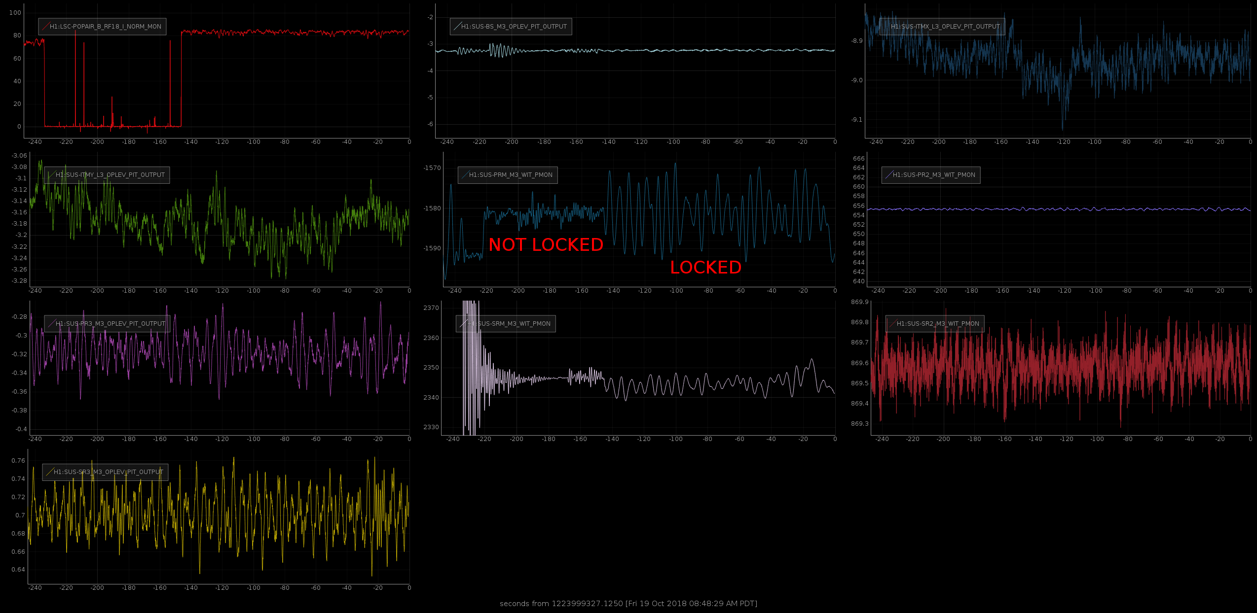
In the last few days we always had a pitch motion very well visible in the AS port, when locked. It turns out that this is due to PRM: when locked, the PRM witness sensor see a 20-30 urad pitch motion at about 150 mHz.
We tried to switch off the top stage offloading, but this did not improve the situation. So we need to rework the M3 stage length to pitch decoupling. What we have right now dates back to 2014...
It looks like this might be a bad diagonalization of the witness sensors.
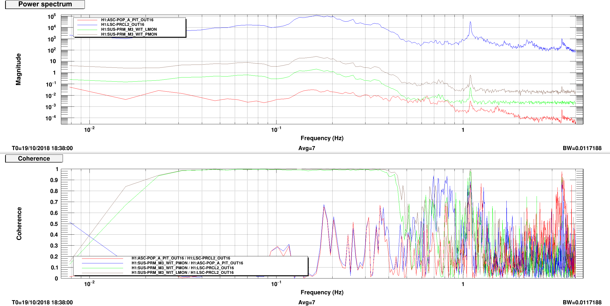
In full lock, I looked at the PRCL longitudinal drive, and at the ASC error signal for PRM pitch (POP_A QPD).
Although the PRM pitch witness sensor is highly coherent with the longitudinal drive and with the longitudinal witness sensor, there is almost no coherence of the PRM ASC pitch signal with either PRM pitch witness nor PRM longitudinal drive.
TITLE: 10/19 Day Shift: 15:00-23:00 UTC (08:00-16:00 PST), all times posted in UTC
STATE of H1: Commissioning
OUTGOING OPERATOR: None
CURRENT ENVIRONMENT:
Wind: 3mph Gusts, 2mph 5min avg
Primary useism: 0.02 μm/s
Secondary useism: 0.22 μm/s
QUICK SUMMARY:
HAMs 2, 3, 4, 5 are tripped both HEPI and ISI. I tried resetting HAMs 2 & 3, and they both re-tripped.
At first glance, it looks like maybe there was a timing glitch, a la alog 43806.
[RichardM, Jenne, KeithT via phone]
I requested all HEPI and ISI guardians for HAMs 2, 3, 4, 5 to "READY", then we restarted all the models on those computers.
I ssh'ed to the computers, h1seih23 and h1sei45, and ran "sudo /etc/startWorld.sh". Richard clicked some DACKILL reset buttons, and we're back. I requested the HEPIs and ISIs to their nominal states, and have started initial alignment.
The BLRMS that Jim has on the wall for HAM5 (alog 44661) look high, but I'm going to wait until he gets in to look into this - it's not stopping me so far.
Gabriele and Sheila had said that locking had been not very robust today, so I checked on the status of the ISIs. Restarting the ISI models zero'd all the gains on the sensor corrections on these ISIs (that was how Hugh and I set them in the safe.snap). The HAM sensor correction guardians didn't re-engage the sensor correction after the restarts. I found this by looking at some lights I added to the SEI_CONF overview. On the attached screenshot, there are a bunch of green indicator lights about a third of the way up from the bottom left corner, where it says "Sensor Correction Gain States". The only red light now is for the EX sensor correction, which is off because of the broken BRS. I guess I haven't advertised this before, but if there is a question about the seismic configuration, this screen is a good place to start. The sensor correction lights don't show everything, but should all be green if we expect everything to be nominal.
Danny, Sheila
Concerning the A2L script, I could not reproduce the problem. My best guess is: sometimes the online NDS connection returns bad data for the first second. So I modified the script so that it discards the first chunk of data it receives.
I also added a check on the arm transmitted power: if LSC-TR_X_NORM_IN is lower than 1000, then the script stops the measurement, since the IFO is likely unlocked.
If the script fails again returning NaNs, you can simply try to run it again.
S. Dwyer, J. Kissel
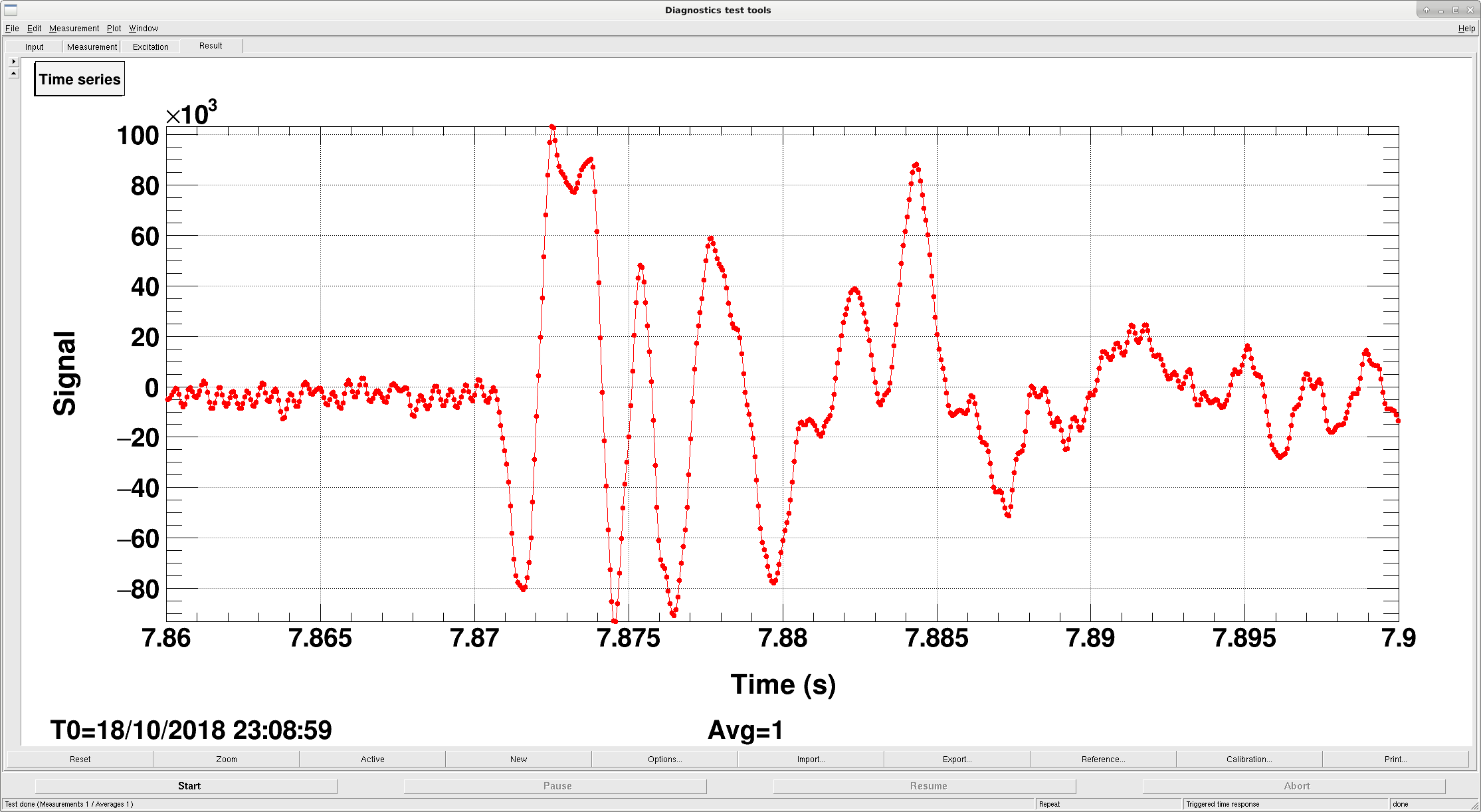
The third attachment shows one of the fast glitches that has been causing our large drops in range. This glitch in particular nearly saturated the ESD DAC, and we think that some of our sudden locklosses could be caused by these glitches when they are slightly larger.
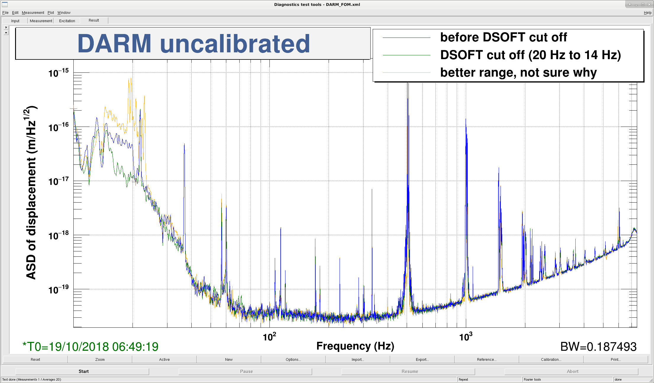
Since the frequency of this glitch is above 1 kHz, we decided to try to roll of the DARM loop a little faster, to make it more similar to LLO's. We copied the soft elliptic low-pass from LLO's violin notch filter.
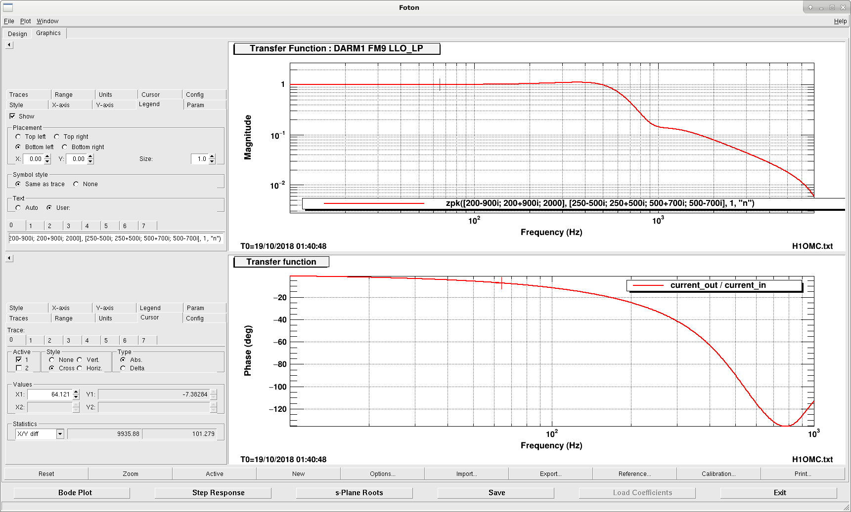
The following filter has been installed into FM9 of the DARM1 bank (replacing an old, unused RG3 filter)
Name: LLO_LP
Design String: zpk([200-900i; 200+900i; 2000], [250-500i; 250+500i; 500+700i; 500-700i], 1, "n").
(see attached BODE plot of the new filter.)
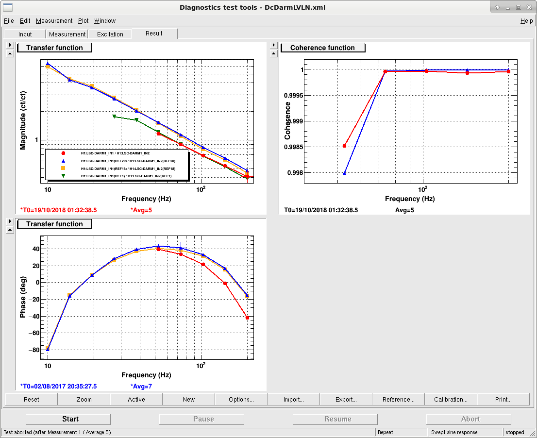
With this new filter, the new DARM OLG phase margin was reduced from ~42ish to 35ish (see attached OLG).
we lost lock right as we were measuring the changed open loop gain transfer function, so it's yet unclear if this improves anything.
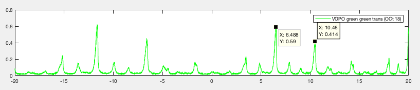
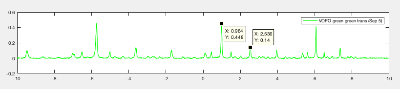
The size of TEM01 compared to TEM00 is much worse than before. 01 mode used to be just 30% of 00 mode back in September 5th. Now it's 70%.
Note that no alignment in air could've caused this. We suspect that the fiber is slowly degrading and slowly spitting out higher order modes.
Here's data from today (top) comparing to data taken on Sep 5 (bottom). Both cavity scan was without the 20dB attenuator on at 80MHz (hence the clearly visible sideband peaks).


The end.
TITLE: 10/18 Day Shift: 15:00-23:00 UTC (08:00-16:00 PST), all times posted in UTC
STATE of H1: Commissioning
INCOMING OPERATOR: None
SHIFT SUMMARY:
Commissioning work continues. EX BRS is dead (until Krishna visits us on Tues).
LOG: See Attached
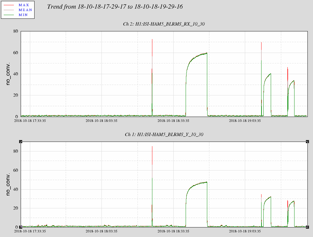
Jim W mentioned there has been an intermittant ~20 Hz noise source observed by the HAM5 GS13s (he mentioned it being seen on the SRM OSEMs as well). Attachment #1 shows channels for Y & RX BLRMS for 10-30Hz where there are times when the noise appears.
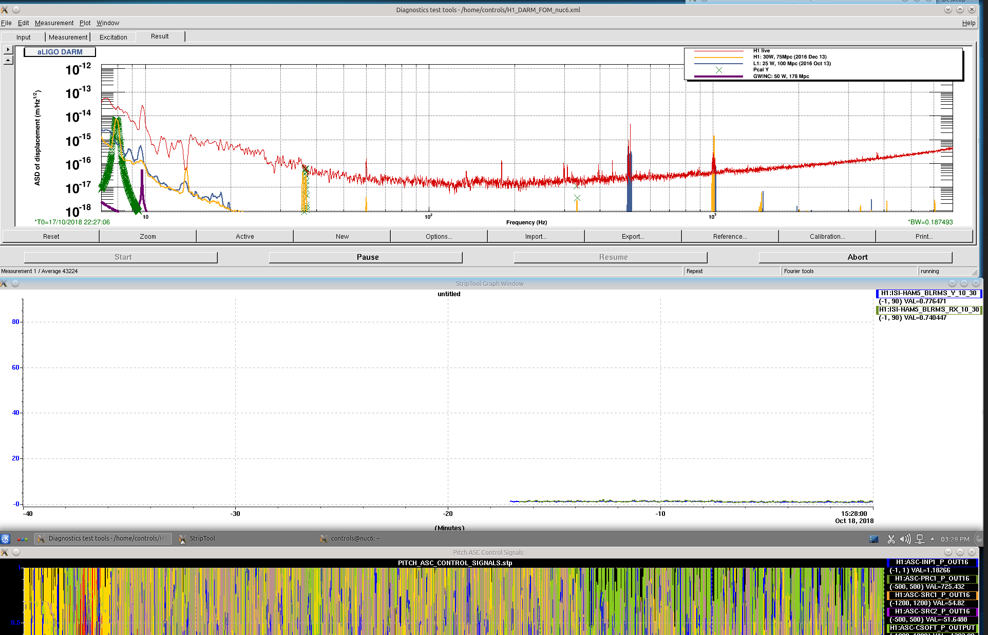
Attachment #2 is a screenshot of nuc6 with the new temporary StripTool for HAM5 ISI. If the channels here stray from 0, then there could be an issue with the SRM/HAM5ISI.
Daisy chain OMC DCPD signals going to split whitening chassis in ISC-R5 U18 through squeezer OMC/homodyne chassis in ISC-R5 U16 (requires DB25 jumper cable).
For the DCPD whitening chassis this should make no difference, and only look like a slightly longer cable. The squeezer OMC DCPD chassis routes all signals straight through, picks off the DCPD signal and extracts the 3.125MHz LO locking signal.
It should now be possible to engage the ISS second loop by requesting the state ISS_ON of the IMC guardian. This state engages an AC coupled ISS loop.
The you can request the state ISS_DC_COUPLED. This state for now just switches off the digital AC coupling. It used to have the engagement of two boosts: for now I left them out, since we need to be at high power to ensure that the ISS second loop has enough gain to be stable with the boosts.
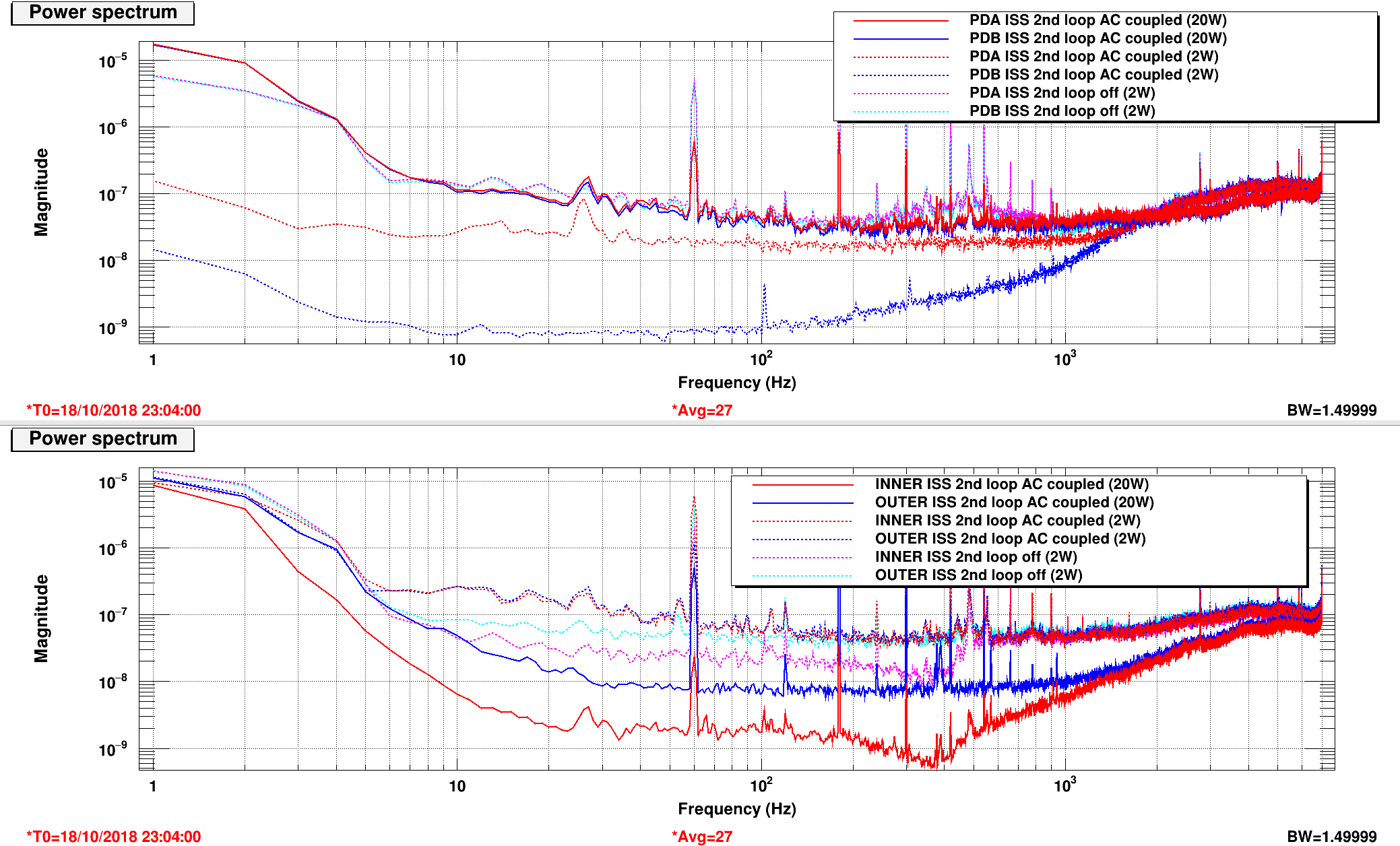
I tested the switching on and off at 2 W. The third plot shows both the first loop (PDA and PDB) and second loop (INNER and OUTER) signals in the three different configurations: ISS 2nd loop off, ISS 2nd loop AC coupled, ISS 2nd loop DC coupled (no boosts)
To be tested at high power (including the boosts)
Some details
[Daniel, Gabriele]
Changed the gains of AC coupling "prediction" path to adjust for new power levels:
H1:PSL-ISS_SECONDLOOP_PD_CAL_GAIN = 1.0 (was 1.2)
H1:PSL-ISS_PD_NORM : FM2 changed to gain(0.079) was gain(0.113)
Now the output of H1:PSL-ISS_PD_NORM is close to one.
Second loop successfully engaged in full IFO lock, up to 20 W.
We tried the DC coupling at 2 W (no boosts) and it did not work (refracted power running away), to be investigated.
After today's maintenance and restart of the ISS model, the second loop is no more working at powers above ~10 W. It's fine to engage the second loop at 2 W, and to increase the power to 10 W. Above that, the loop drives the diffracted power very high.
It's not clear if the problem is to be traced to some configuration parameter in the ISS model, or to the fact that the diffracted power is now larger (2.4% instead of 1.4%).
More dedicated time is needed to investigate the problem.
Empirically CM gain and 100Hz noise are correlated (alog 44585) but the sense among us is that it's not residual frequency noise (at least via linear coupling), as no coherence was observed between DARM and signals like CM board output and POP9I etc.
To eliminate the possibility that 100Hz noise is the linear coupling of gain-limited residual frequency noise, we need to show the following.
This alog shows that the first point is true.
In the attached, left middle shows LSC-REFL_SERVO_CTRL_OUT_DQ when there was no light on REFL_A (green), and in low noise state before CM gain setting was made incorrect on Sunday (red) and with an incorrect CM setting (blue).
Both red and blue are more than an order of magnitude larger in-lock than the green trace, so apparently it's not limited by the ADC and read out electronics noise.
In the middle right is the CAL-DELTAL_EXTERNAL_DQ (without necessary calibration TF applied), just look at red/blue difference, blue is about a factor of 2 larger than red at 80Hz. If this is a linear frequency noise coupling it should be obvious in the coherence (left bottom) but there's really nothing to talk about while there's a clear difference in coherence at higher frequency.
In conclusion, the point 1. listed above is correct, yet there's no coherence for broadband 100Hz-ish noise, and therefore it's unlikely that this is linear frequency noise coupling.
Without addressing the point 2 (as it sounds unlikely), the next thing is to see if this is nonlinear coupling of the frequency noise. Injections would be useful, looking at demod signal of REFL_A_RF9_I would be useful, and changing CM gain somewhere in the chain would be useful.
FYI, in the above entry, CM gain difference between red and blue was 11dB or a factor of 3.5, and that was downstream of the REFL CM board (i.e. IMC REFL CM board IN2 gain). So at least red/blue difference of REFL_SERVO_CTRL_OUT as well as REFL_A_RF9_I_ERR make sense.
But comparing DARM red/blue doesn't make much sense as the coupling is also somehow related to the heating which is apparent from how the range degrades over time together with the frequency noise in DARM in kHz range when CM gain setting was wrong.
More explanations of the above.
Linear coupling to REFL sensing noise (shot noise etc.) imposed on the frequency noise was rejected right away because if that's the case CM gain change wouldn't make any impact whatsoever.
Since it changes with CM gain, and since we see no coherence anywhere, the true frequency noise is either somehow entirely gain-limited (not sensor limited) but all our signals are limited by ADC noise, which was rejected in the above, or it's sensor-limited at 100Hz but the gain-limited part of the noise (e.g. kHz or DC-ish frequency) is somehow down/up converted to 100Hz. In the latter case, it's an equivalent of additional REFL sensing noise and cannot be detected in-loop.
Due to fire department work on site.
Bypass will expire:
Thu Oct 18 13:10:42 PDT 2018
For channel(s):
H0:FMC-CS_FIRE_PUMP_1
H0:FMC-CS_FIRE_PUMP_2
fire pump work has started up again, some alarms have gone out. I've re-issued the bypass
Bypass will expire:
Thu Oct 18 16:40:20 PDT 2018
For channel(s):
H0:FMC-CS_FIRE_PUMP_1
H0:FMC-CS_FIRE_PUMP_2
Today I requested twice the state CHECK_MICH_FRINGES, and then requested PRMI_LOCKED. The guardian went straight to the end of PRMI_LOCKED, reporting the state to be concluded, even if PRMI was NOT locked.
This is a result of my adding locking ability to the CHECK_MICH_FRINGES state. To get the MICH length to lock, I had to force the MICH LSC trigger. But, CHECK_MICH_FRINGES to PRMI_LOCKED doesn't force the DRMI guardian to go through PREP_DRMI, so the threshold wasn't getting reset for PRMI acquisition. I have added to the PRMI and DRMI guardian states resetting the MICH LSC trigger, so that guardian (which just looks at the triggers to decide if PRMI is locked) realizes that PRMI isn't actually locked yet and will go through the prep states that it needs to do.
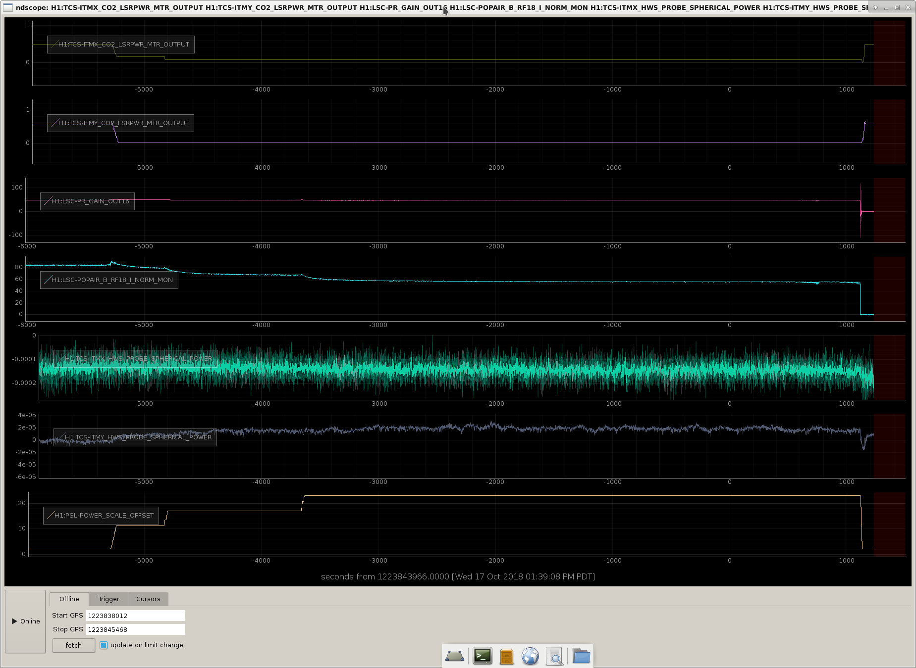
It might be useful to summarize the TCS changes made from Monday to today:
| CO2X | CO2Y | PRG | RF18 | |
| IFO COLD (2W) | 0.5 W | 0.66 W | 49.5 | 94 |
| IFO HOT (20 W) | 0.11 W | 0.09 W | 47.5 | 52.5 |
ITMX RH @ 0 W
ITMY RH @ 1.04 W
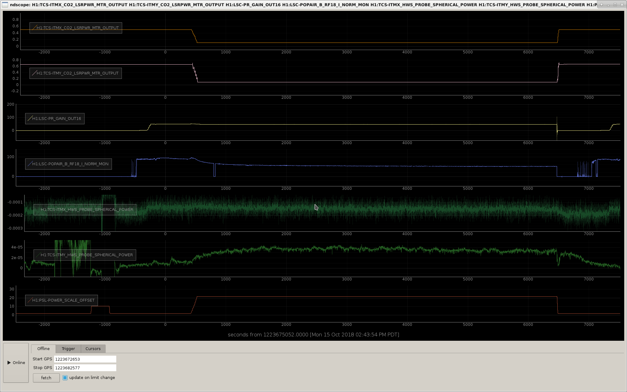
Please see first figure for relevant time series of a 20 W lock stretch
| CO2X | CO2Y | PRG | RF18 | |
| IFO COLD (2W) | 0.5 W | 0.6 W | 48 | 83.5 |
| IFO HOT (20 W) | 0.1 W | 0 W | 47 | 56 |
ITMX RH @ 0 W
ITMY RH @ 1.74 W
Please see second figure for relevant time series of a 20 W lock stretch
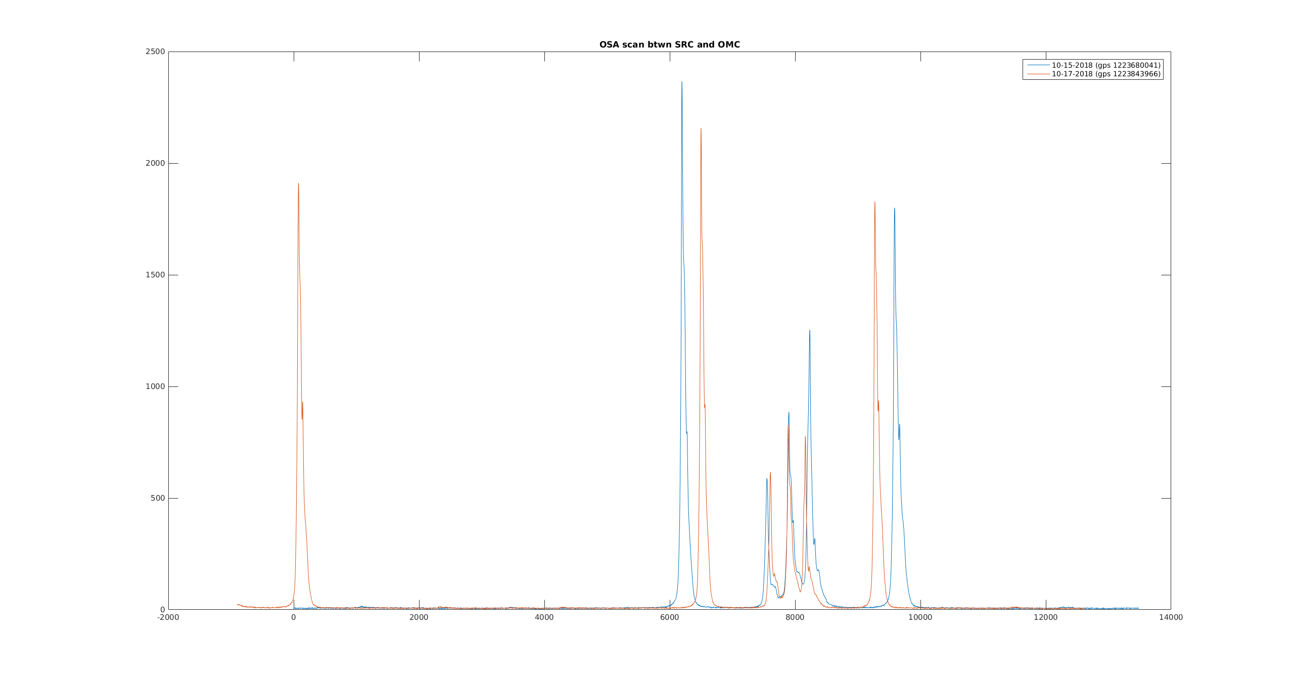
The following two tables list the carrier and sideband power when at 20W:
| 10-15-2018 | 10-17-2018 | |
| carrier (counts) | 826 | 856 |
| 9 MHz upper (counts) | 1252 | 777 |
| 9 MHz lower (counts) | 589 | 617 |
| 45 MHz upper (counts) | 1800 | 1828 |
| 45 MHz lower (counts) | 2366 | 2158 |
The new TCS settings seems to have improved the balance between the 9 MHz sidebands, and RF18 when at 20 watts.
TCS to do list:
CO2X is now at .2 watts when PSL input is at 2W. This was done because on Tuesday we tried to increase CO2Y to compensate for the ring heater change but it just made locking difficult.
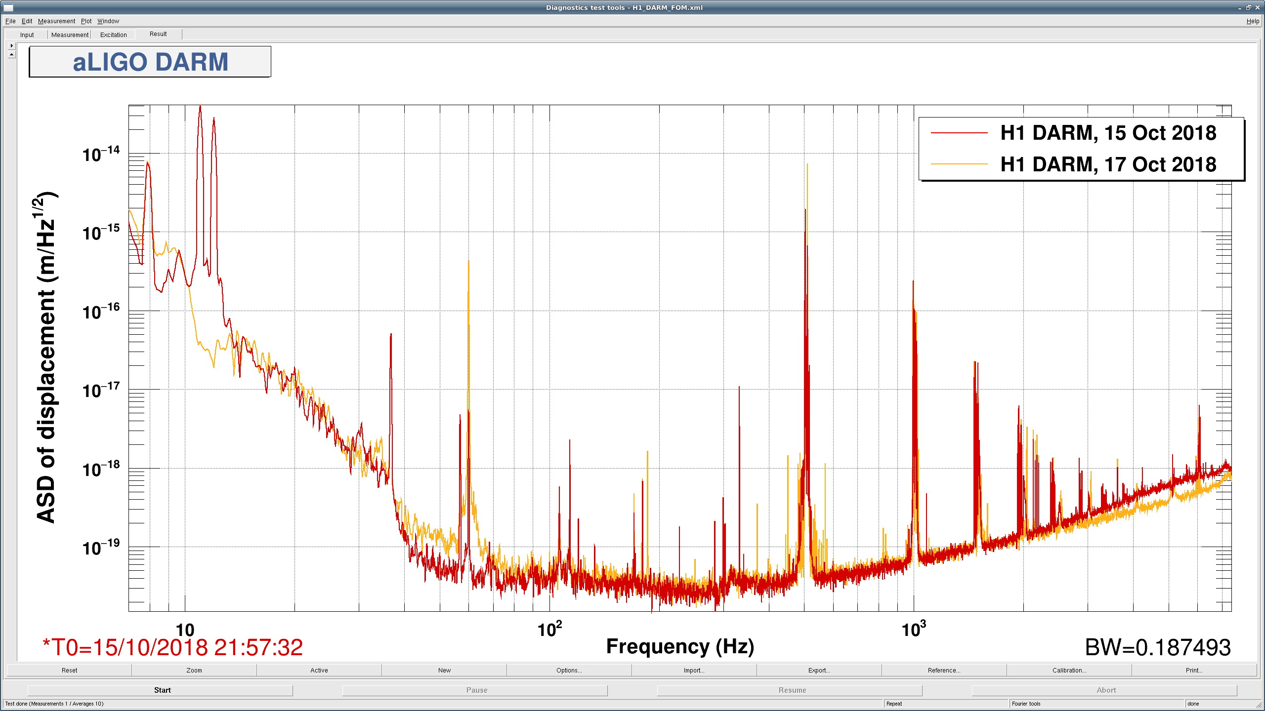
The 60Hz line is *very* bad today. I don't think we noticed it yesterday since we weren't really going to Nom Low Noise, since we were doing TCS tuning instead. But, it's incredibly clear that something happened between Monday and today that has made the 60Hz line very bad. If DetChar wanted to have a look at what witnesses see this, that would be helpful.
I don't think that anything happened with the ETMX ESD power supply yesterday. (It was going to be swapped out, but JeffK asked around, and it doesn't sound like we got that far before the end of maintenance yesterday).
Apparently the ETMY ESD driver had been removed on Tuesday, and the cables were left un-terminated. The modifications to the driver are complete, so this afternoon the driver was re-installed, and now the 60Hz line is much improved.