andrew.lundgren@LIGO.ORG - posted 04:13, Tuesday 16 October 2018 - last comment - 14:35, Saturday 20 October 2018(44580)
Beginning of 56 Hz comb located
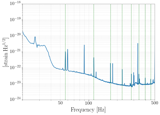
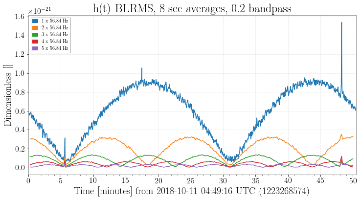
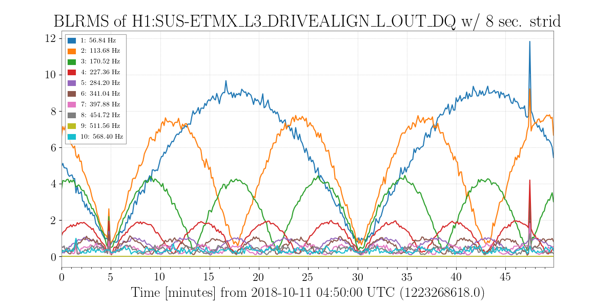
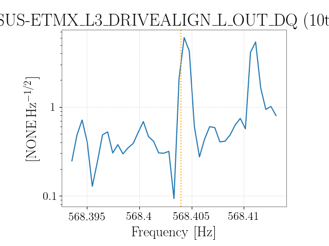
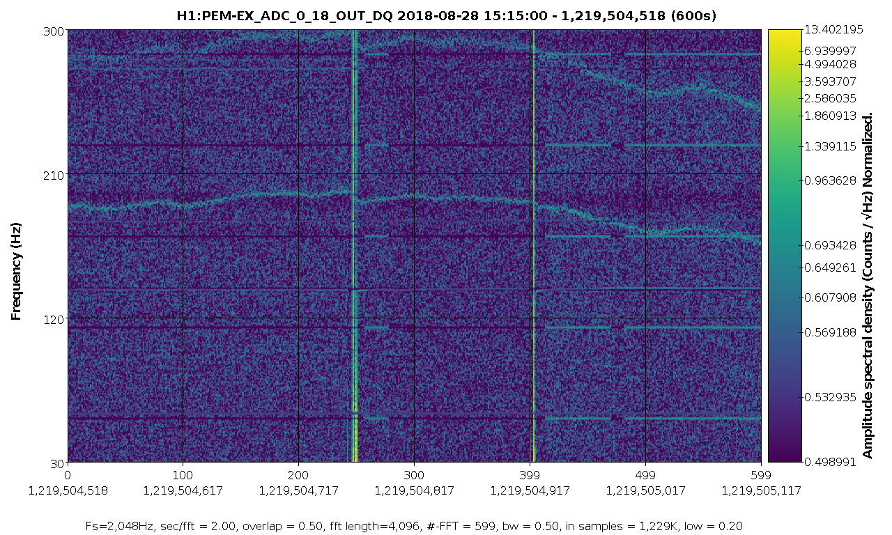
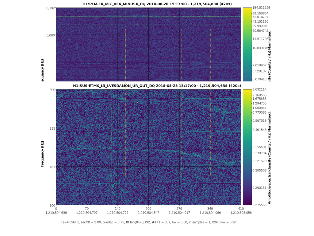
There is a comb in h(t) at 56.84044 Hz and multiples, identified in the Oct 11 low-noise data, with extreme amplitude modulation.  In alog 44495 and follow up, it is found to be in many EX channels, including unused ADCs in the PEM system. The time when this line began has now been tracked to August 28 15:20 UTC.

The attached spectrogram shows the lines appearing. The most likely cause that I can see in the alog is an update of the TwinCAT system manager on h1ecatx1. This is logged as starting at 14:54 UTC (alog 43706, and alog 43697 seems to indicate that the restart happened at 15:20 UTC.
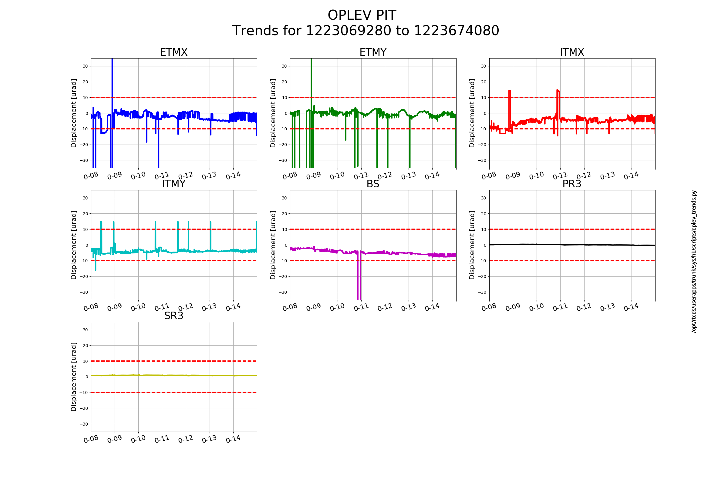
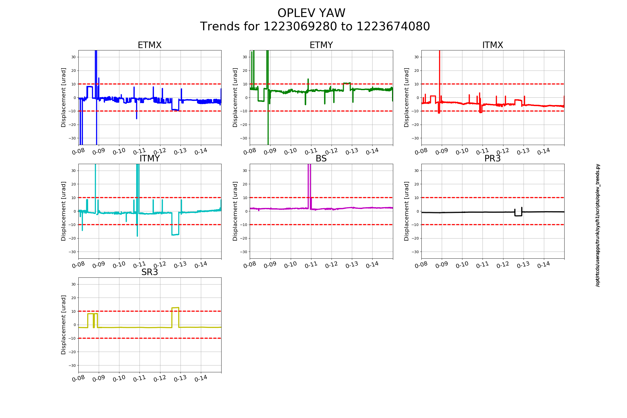
Images attached to this report
Comments related to this report
I've found that there are sounds in the EX MINUSX mic related to the 56.84 Hz line beginning. There are a number of clicks, which sound like a door being opened or electronics boxes being opened. At each one, the 56.84 Hz either appears or disappears or there is a broadband glitch in the electronics. So it seems that the reboot is not the cause, rather something was jostled.

Attached are a spectrogram, and an MP3 of the microphone, in case anyone recognises the sounds. I didn't see anything in the other PEM mic signals at EX.
Images attached to this comment
Non-image files attached to this comment

Andrew, what a nice observation. It sounds like an electrical relay contact opening and closing to me. I don't know where this microphone is physically located in proximity to the air conditioning equipment for the EX VEA, but a component of that system is the first thing that comes to mind. Perhaps the heaters that are part of the dehumidification and temperature control scheme? Are you able to see correlation of the glitches iin the magnetometer?
There's a map and a picture of the location on pem.ligo.org. It looks like it's under the beam tube, near the floor.

Since Aug 28, I haven't found any time where the line goes away in the ADC. It wasn't there before those noises, and it also hasn't changed since. We could check this in more detail if needed (I've just chosen a few dozen times at random). Was there anyone at End-X at this time (Aug 28 15:20 UTC), or was all of the work remote?
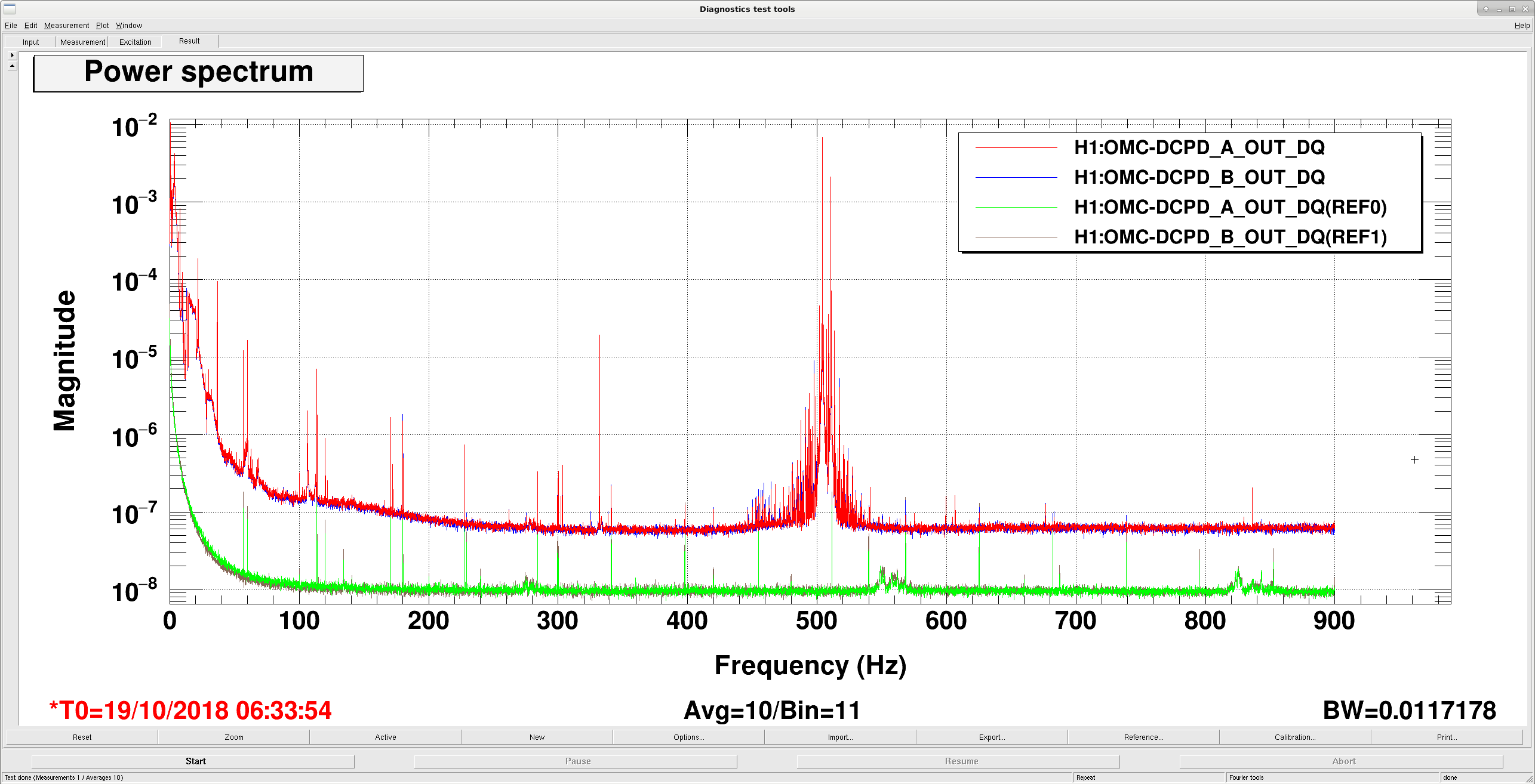
FYI, 56.8Hz and its harmonics were present in DCPDs last night even when there was no light, though the amplitude when dark was much much smaller than in-lock.
Red and blue are when IFO was locked with 20W, green and brown are when IFO was left unlocked last night and no meaningful light was coming to AS port.
Maybe this is a potential problem for all stations, just that it got much worse at EX on Aug 24?
Images attached to this comment
Nice catch, Keita! I think this may be the cause of the amplitude modulation. The EX comb is at 56.84044 Hz, and the CS has a comb at 56.84078 Hz. DARM, in lock, seems to be a mixture of the two.

I've found this comb in a few of the apparently unused ADCs for the CS PEM. The frequency is the same as seen in the DCPD when it's dark, as pointed out by Keita. The line is very stable and can be well-separated from the frequency in EX, especially when looking at the higher harmonics. The first plot shows these two lines in the ADCs. EX is marked by the red vertical line and CS by green.

The second plot compares the DCPD when dark and in lock. Only the CS line is evident when dark. When in lock, it's harder to resolve the lines since there's not as much data. But it is clear that the CS line disappears. But now there are symmetric sidebands around where it was: one matches the EX line, and there's a new line marked blue which is mirrored across the CS line. The separation of these matches the amplitude modulation seen in DARM with a 50-minute total period.

It's hard to understand the exact mechanism here, and why the central line should disappear. It does seem that both CS and EX have combs but they can be distinguished by the precise frequency (needs 0.1 mHz resolution).
Images attached to this comment