J. Kissel, E. Goetz
Apologies for our lack of reports thus far, but here's an update since we last logged (LHO aLOG 44459).
= Tuesday (10/09)
- Installed a ton of new infrastructure in order to improve the calibration pipeline in prep for O3. This is installing the changes as per ECR E1800246 and IIET: 11305, 5205.
- Worked hard on building MEDM screens in order to identify bugs in our new installation. This resulted in several restarts of the PCAL and CALCS models and the DAQ (see LHO aLOG 44440) that took us to the end of the day.
= Wednesday (10/10)
- Continuing to create / update MEDM screens to reflect the forward looking changes mentioned above
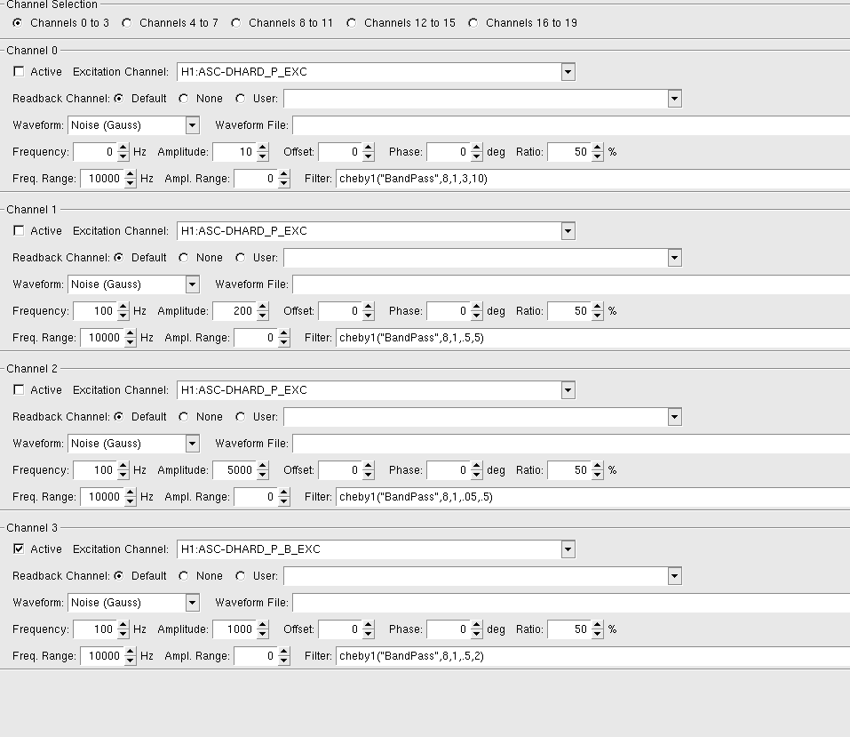
- Measured the actuator transfer functions for the current DARM control configuration (EX L3 ESD with PCALX as reference, EY L2 Coils, EY L1 Coils with PCALY as reference)
- Began to exercise python processing the actuator transfer functions (similar to the python processing of the sensing transfer functions; LHO aLOG 44364), updating the code to work with the new infrastructure.
= Thursday (10/11)
- Diverted attention from completing MEDM screen upgrades and filling in new infrastructure (apologies again, this means the calibration screens are in complete [visual] disarray, and downstream data analysis products will continue to be broken. Thank you for your patience.)
- Continued and finished processing actuator measurements for all actuation stages
:: Identified that we do not have accurate compensation of the ETMX ESD Driver low pass filters (resulting in a linear-ish frequency-dependent systematic error from 5% too high at 20 Hz to 5% too low at 800 Hz), slightly confusing our estimate of the scalar actuation strength of the stage.
:: (Re-)Identified that we have the same systematic error above ~30 Hz in our dynamical model of the UIM stage due to non-1/f^6 dynamics known to be present in all QUADs (see LHO aLOG 38295), so we only use ~5 data points to fit.
- Reviewed the MESS of confusing signs to keep track of given our using two PCALs and two QUADs to drive DARM
- Updated the front-end parameters to reflect all new information, including
:: updating and triple checking the replicas of all digital control filters and gains
:: updated physical actuator strength coefficients
:: better and more explicit definitions of each sign flip in each path
:: newly calculated Sensing to Actuation relative delay
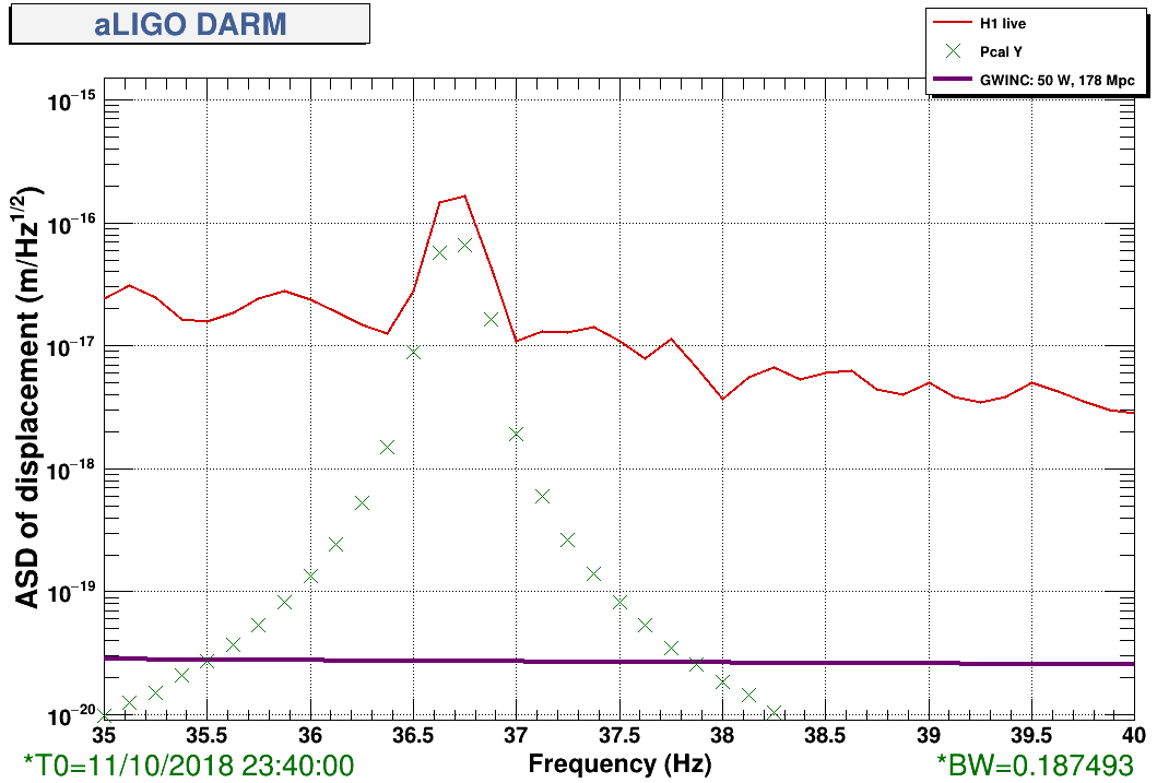
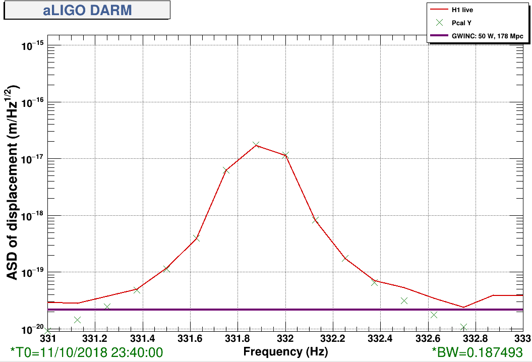
and sadly this failed to produce an accurate low-frequency calibration (with our metric being the PCAL Y 36.7 Hz line showing a discrepancy with DELTAL_EXTERNAL of ~2.6; 331.9 Hz line is still very good after last week's sensing function update [LHO aLOG 44364])
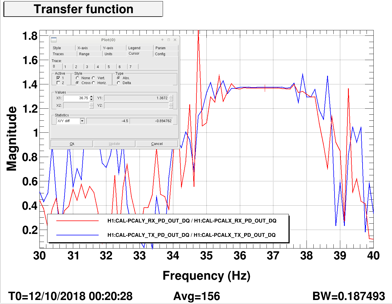
- Measured the PCALX vs. PCALY RX PD (and TX PD) transfer function, worried that PCALX reference calibration is wrong thus giving us a wrong answer for the ETMX ESD actuation strength (merely superstitiously, because we recall the PCAL team's recent work on the PCAL EX laser; see LHO aLOG 44305). Using the same drive frequency, and the same drive *amplitude* (in DAC counts to the AOM), the transfer function ratio between X-end RX and Y-end RX (and similarly in the TXs) was 1.36 (or 0.73). However, we realized that we don't calibrate the drive amplitude, so the same counts amplitude does not necessarily result in the same laser power going out to the test mass (say, if the optical follower servo loop gain surrounding the AOM was different between transmitters).
- Tried adjusting the updated ETMX L3 ESD strength by the 30 Hz discrepant factor of 2.6. Didn't work.
- Remeasured the actuator transfer function of EX L3 ESD with PCALY as reference. The answer is the same within ~3%. No dice. The PCALs are exonerated from the "factors of 2" level problems we're having.
We have reverted all changes to have the calibration it was before we started making actuator changes today (10/11).
This leaves the calibration wrong at 36.7 Hz by ~25% , and the 331.9 Hz line within 2%.
We'll resume our efforts to understand the discrepancies tomorrow.