jenne.driggers@LIGO.ORG - posted 16:50, Thursday 11 October 2018 - last comment - 17:57, Thursday 11 October 2018(44481)
Thurs AM locking
- Initial alignment, since Yarm green looked bad, and lost lock at TRcarm.
- Set dark offsets of POP_A_45. Was unable to lock Xarm IR for initial alignment.
- Keep losing lock at the start of CARM_150pm
- Undid Craig's addition of 3dB in IMC_IN1GAIN. This was done by changing the new lacparams.IMC_IN1_gain from 28 to 25.
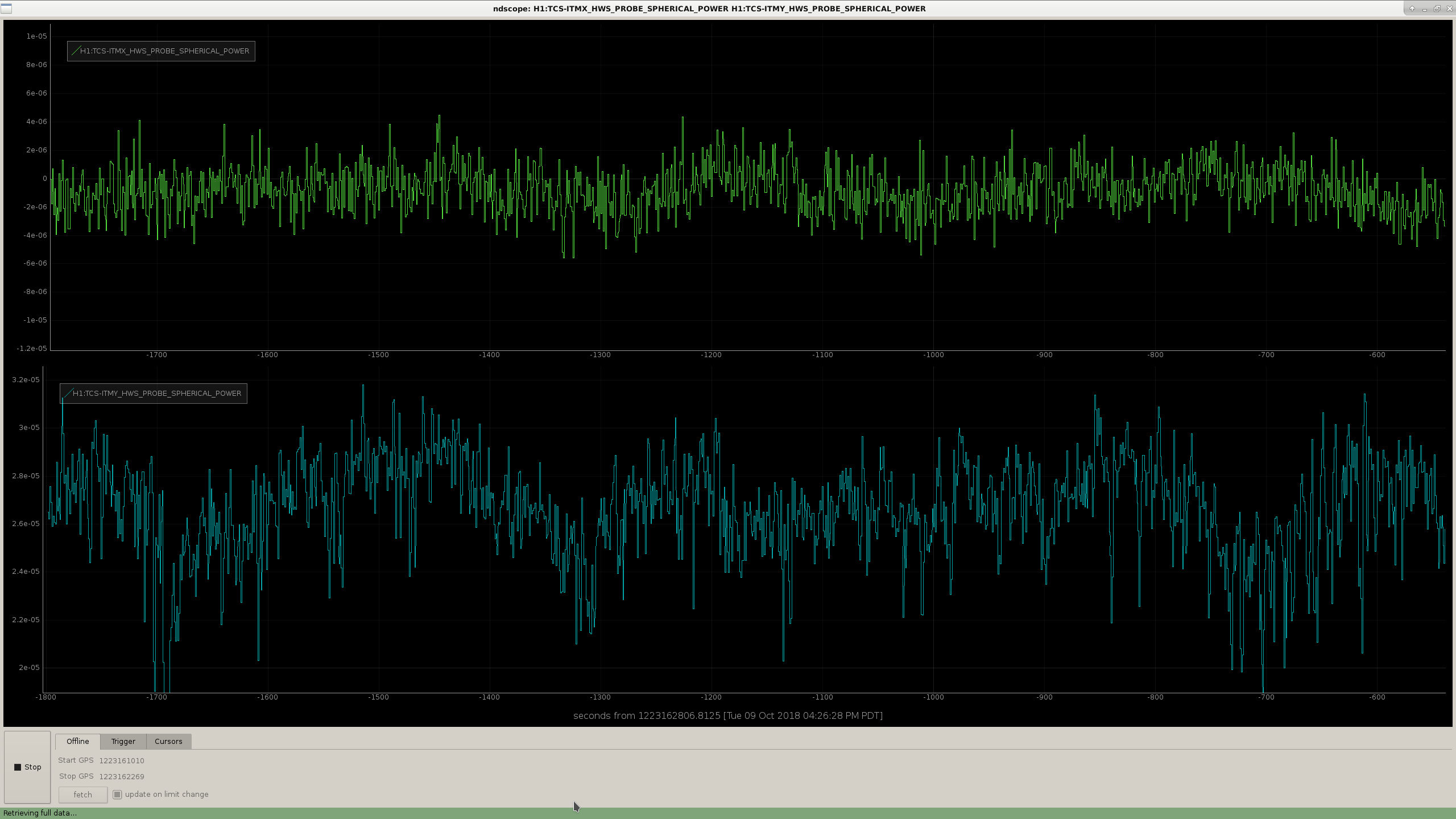
- Big 1Hz osc in IR arm powers, but don't see it in green arm powers.
- Turning off REFLBIAS FMs 4, 10, which are turned on at the end of CARM_TO_TR, gets rid of this osc. These reduce the low freq gain by 35dB. These are currently commented out in guardian. (Later: moved them to RESONANCE, so they are engaged before transitioning to ANALOG_CARM)
- But, we failed to make the transition to analog CARM.
- ETMY SEI tripped, as did TMSY SUS, perhaps due to BRS work at the end station?
- New lock, moving the REFLBIAS FMs to RESONANCE state seems to have worked smoothly.
- Added code to PREP_DC_TRANSITION so that it will re-request the OMC to lock, if it didn't succeed. (Untested so far)
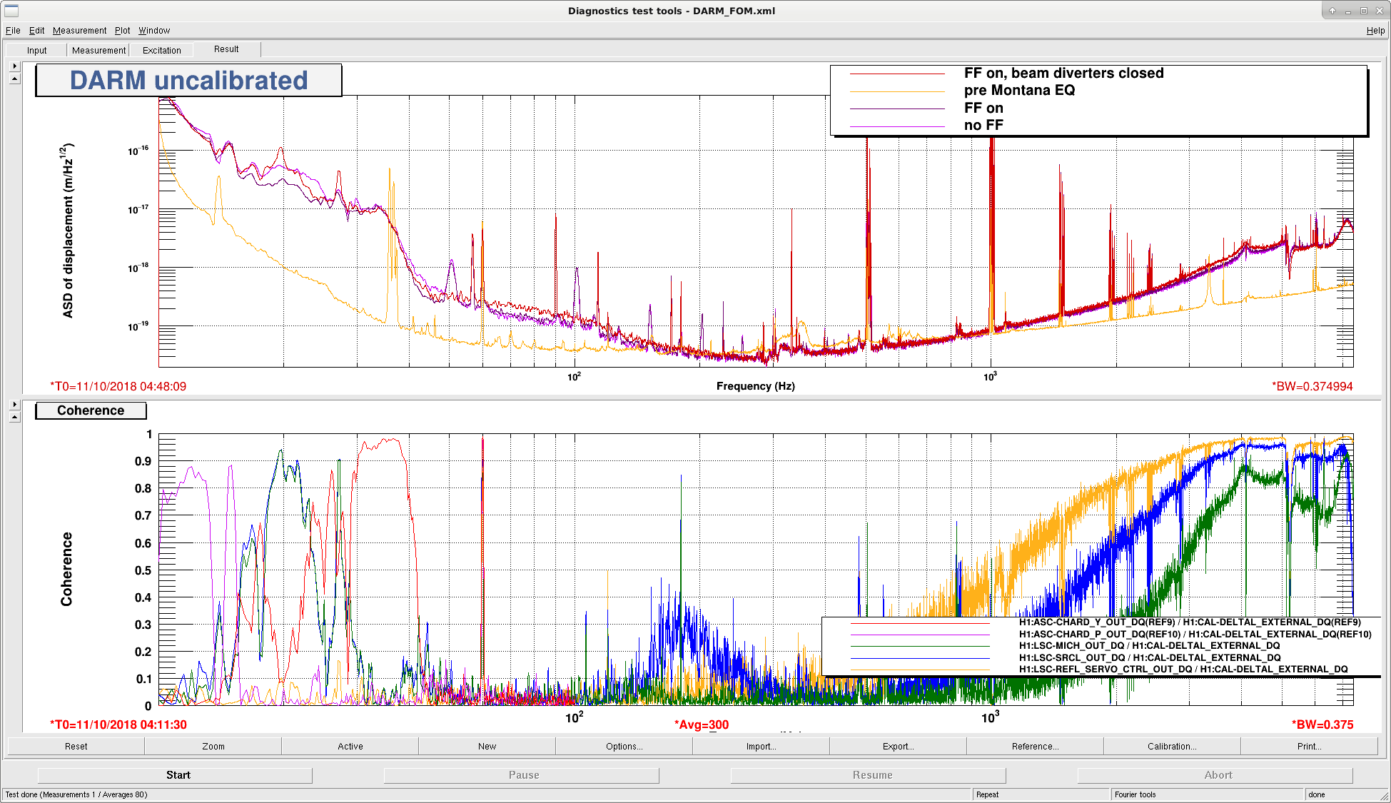
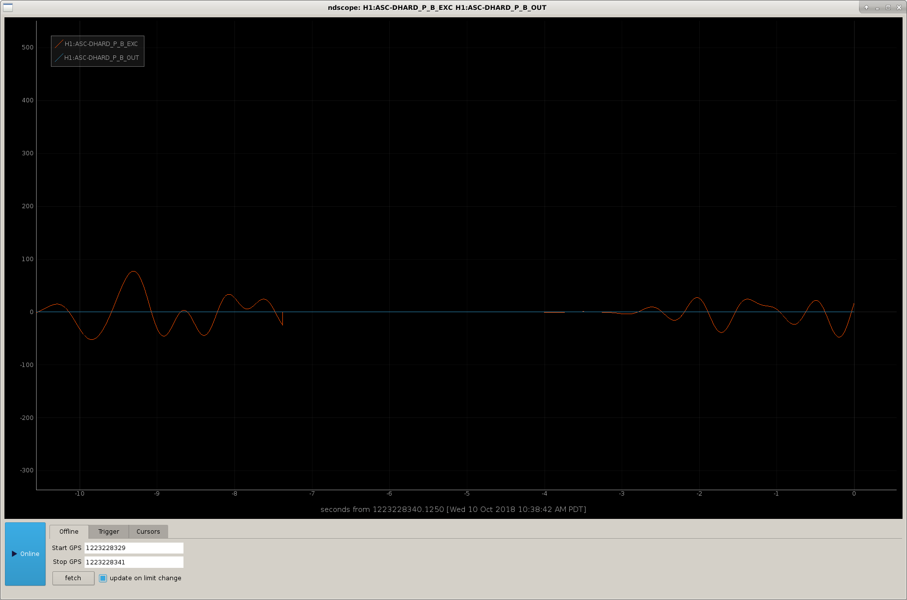
- New lock, after moving pitch SOFT and POP_A offsets. DHARD_P rang up, needed to *lower* the gain to -30. Recall that in alog 44456 I had to *increase* the DHARD_P gain. So, maybe the gain was always okay at -25ish, but we didn't have enough good buildup in the arrm at 20W?
- We were sitting in Close_Beam_Diverters (I had manual-ed there from LownoiseETMX_ESD), and lost lock due to likely human error. But, the IFO didn't recognize the lockloss (which Craig also saw yesterday). I looked, and there wasn't a Run state in Close_Beam_Diverters, so it wasn't checking for lockloss. I have put in a run state that just returns True, so that this state will now bring us to DOWN if we lose lock.


We added back in the filters in REFLDC BIAS in the TR_CARM step. If we increase the gain in the IMC board input, we change the gain of the input for CARM, this was probably the cause of problems.