Craig, Sheila
We were testing a change to the increase_power state, and set the requested power in lsc_params to 5W. We normally manually go to the ADJUST_POWER state if we want to manually change the requested power, but this time we accidentally adjusted the power from LASER_PWR while ISC_LOCK was still in increase power. We lost lock, but the ISC_LOCK guardian went into error and didn't run down, saturating a variety of suspensions until we manually turned things off. This is a risky situation for the interferometer.
It seems like the cause of the problem was that we set the requested power to 5W, which the log of ISC_LOCK says was an invalid request for LASER_PWR, although it is a state. I don't understand why this happened.
Update:
The INCREASE_POWER state in ISC_LOCK had a couple of errors (we were relying on nodes.arrived when we really wanted node.done and node.arrived and a mistake with the counter) that caused it to continuously make same sate redirect requests of LASER_PWR. I edited the guardian in order to avoid this in the future. I don't know if this will fix the problem we had, but we've had strange behavior in the past with same state redirects 43599
(Correction on Oct/09: POP_A RF 45 Q ADC saturation, not I.)
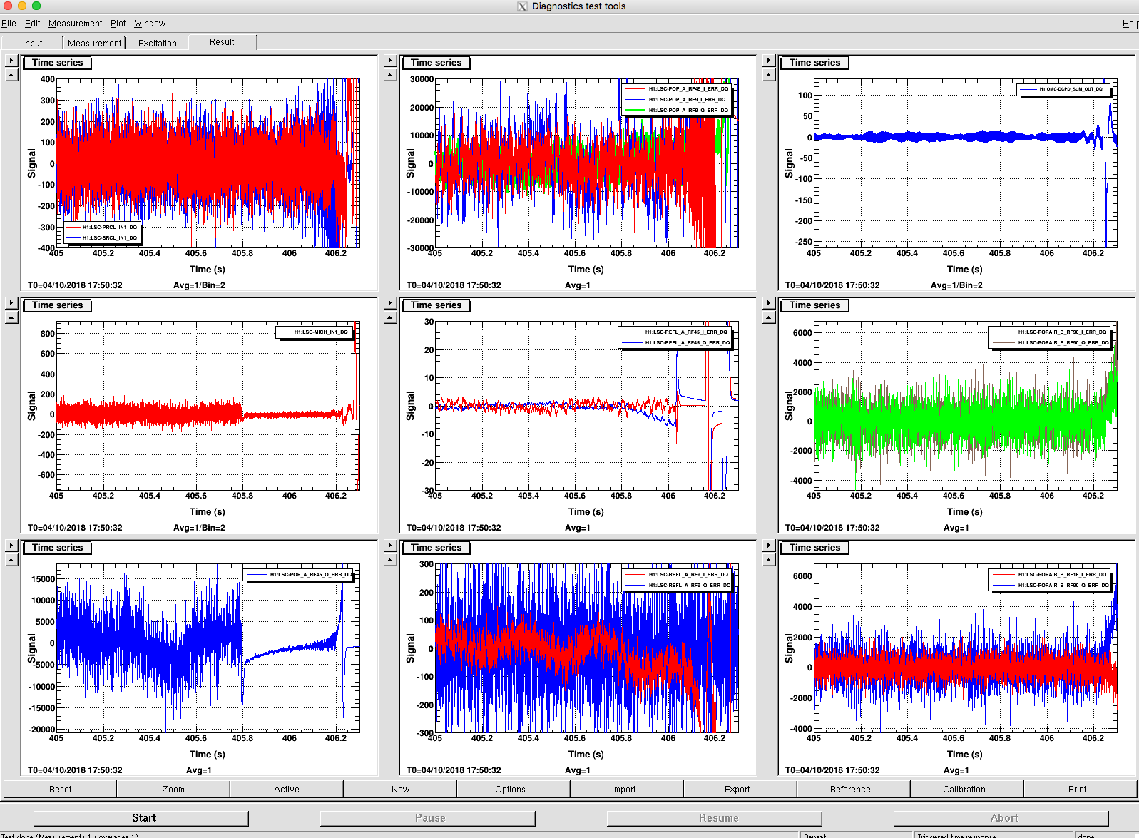
I was looking at the lock loss at around Oct/04/2018 17:57 UTC with 15W, which Jenne told me "may" be the fast lock loss. In the attached plots the power in the arms is lost at about 406.3 sec mark.
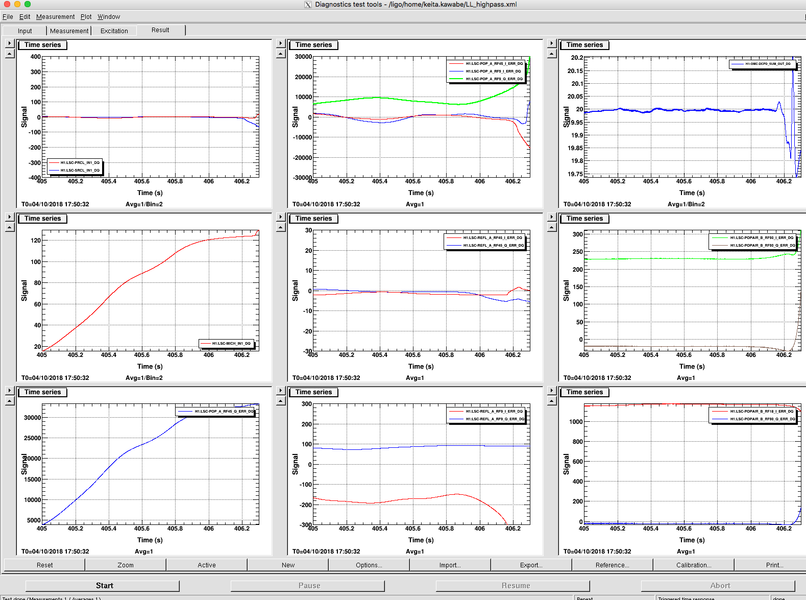
Since I wanted to see what happened to which signal first, in the first plot I high-passed all relevant LSC signals by zpk([0;0],[70;70],1,"n"), and it's clear that it's MICH and specifically POP_A_RF45_Q_ERR that lost sensitivity at 405.8sec (left middle and left bottom) at first. The disaster didn't propagate to OMC, REFL, SRCL and PRCL until 406.2 sec.
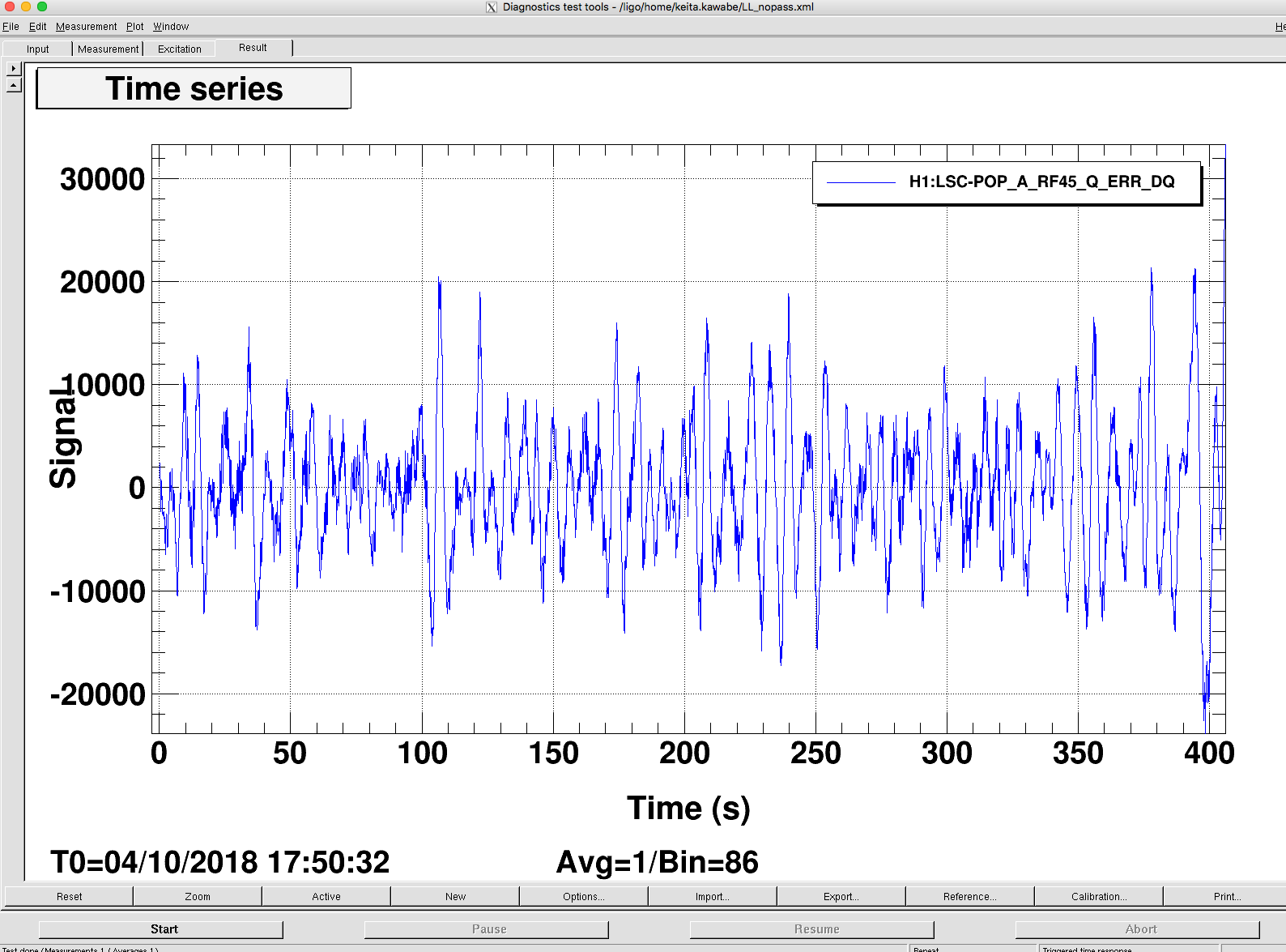
Removing low-pass (2nd attachment), from POP_A_RF45_Q_ERR signal it's clear that POP_A_RF45_I POP_A_RF45_Q before rotation hit the ADC ceiling (ERR signal is post-rotation and post-dewhitening, but the rotation angle for POP_A is about 90 0 degrees).
Before losing lock, for about 400 seconds it was going between +-20k counts, which is marginal at best for post-dewhite signal, and when the disturbance becomes larger than usual it rails.
I don't have time to analyze other lock losses tonight but I'd say we have to reduce whitening gain by at least 12 db or so. It's unclear if this is the cause of so-called fast lock losses but we need to fix this anyway.
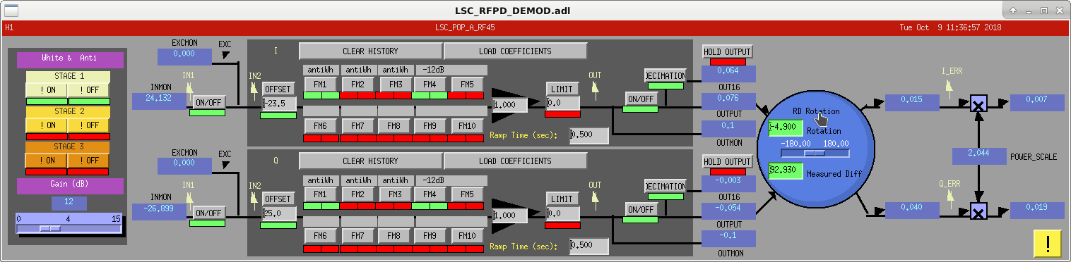
Craig and I reduced the POP_45 whitening gain from 30dB to 12dB, and added a gain of 7.943 to the digital filters. This seems to have helped a lot as had two locks of about 1.5hours at 10W tonight. We didn't try powering up higher, but it would be an easy to check to see if the problem is totally gone.
We didn't check the dark offsets yet because we adjusted this in lock. We should probably go around and add filters that undo the whitening gain to all of our PDs, so that we don't end up with these random gains in so many of them. That will require changign the input matrix through, so I will not do it now.
(Sheila, Keita)
With the whitening gain of 12dB.
This is a total of a factor of 32, and this was reallocated by Sheila to
The idea is that FM4 (-12dB in this case) is the inverse of the whitening gain. Next time you change the whitening gain, you can just change -12dB filter without worrying about guardian.
Haocun, Nutsinee, Robert
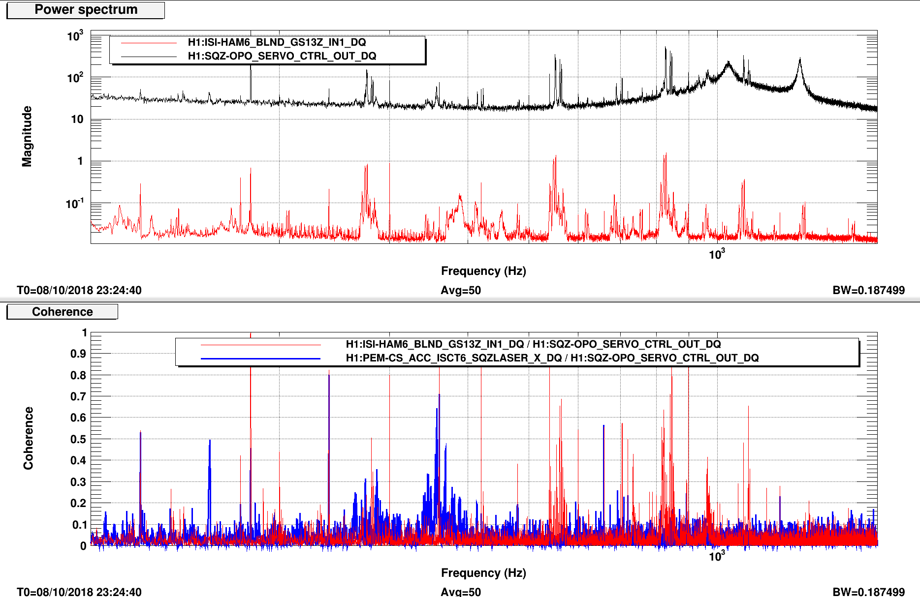
We took a quick look at acoustic noise on H1:SQZ-OPO_SERVO_CTRL_OUT_DQ by exciting optics and the HAM6 chamber. Manual excitation suggested that, roughly speaking, the peaks in the 300 to 400 Hz area were associated with optic mounts on ISCT6, and the peaks in the 600, 800 and 1000 Hz region were associated with vibrational excitation of HAM6, such as the blue piers. This is also what the coherence in the attached plot shows. The HAM6-associated noise is coherent with the GS13s and is at the ISI suspension resonance frequencies (blade springs and wires) that we damped to reduce acoustic coupling to DARM.
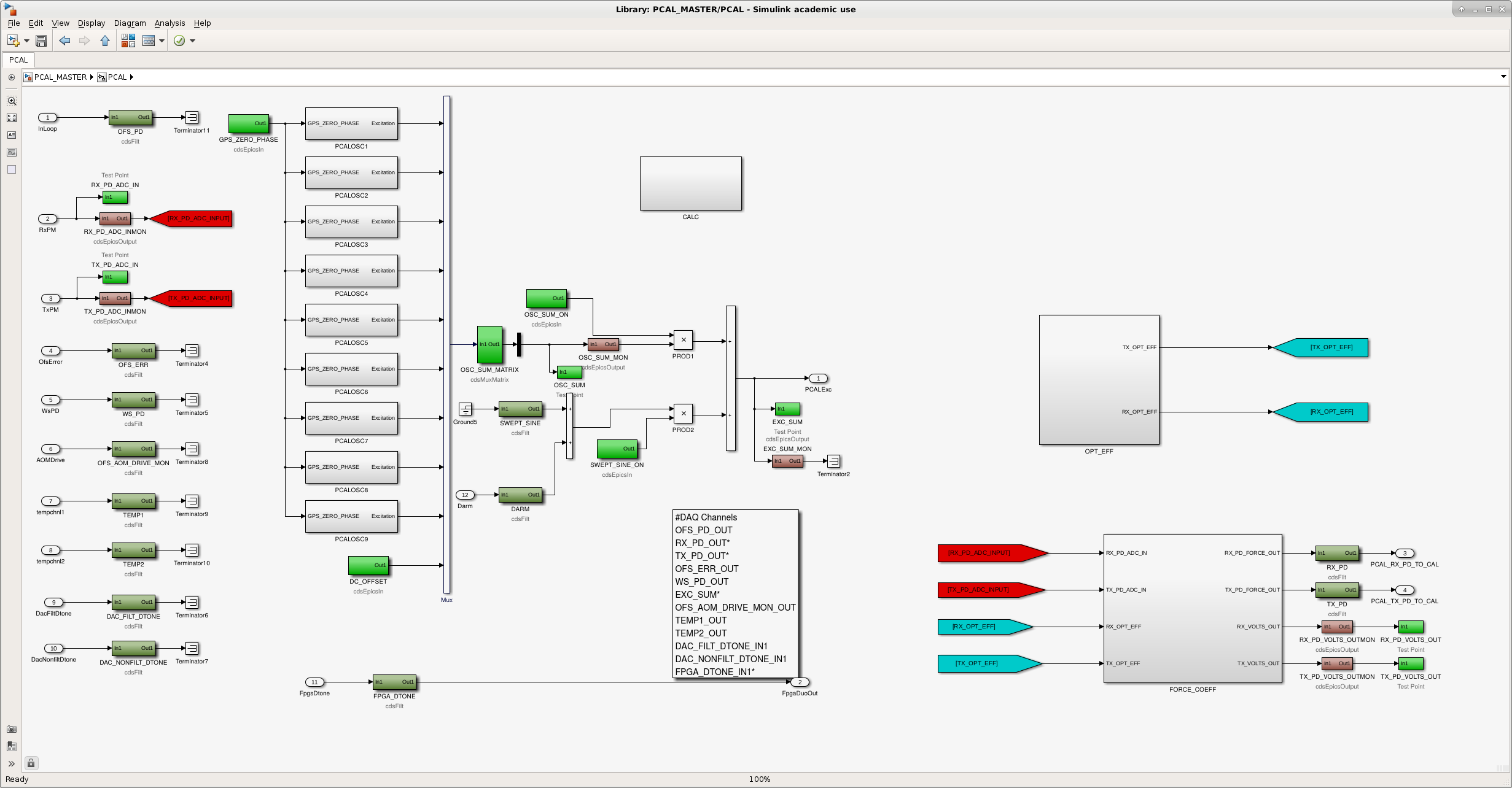
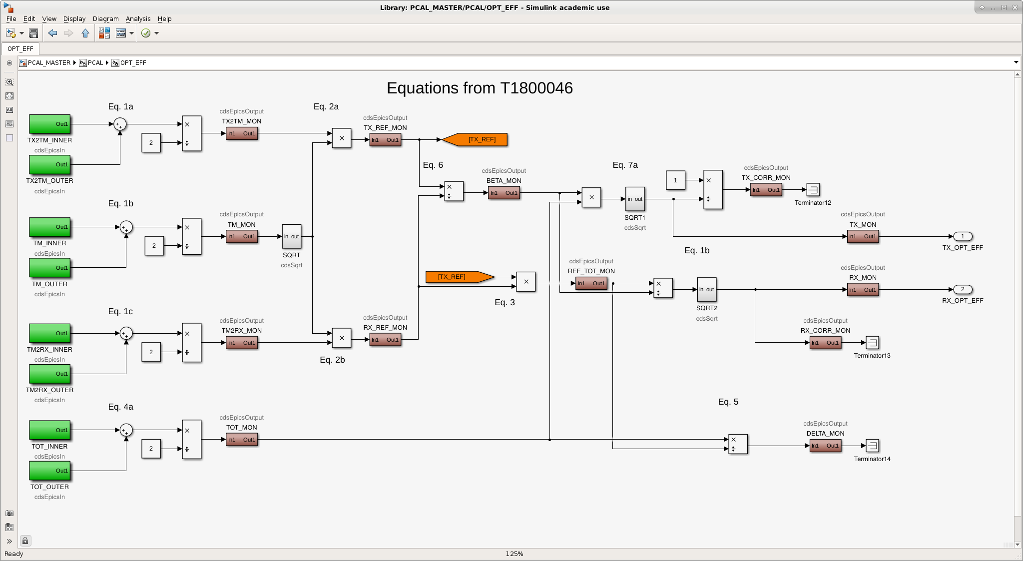
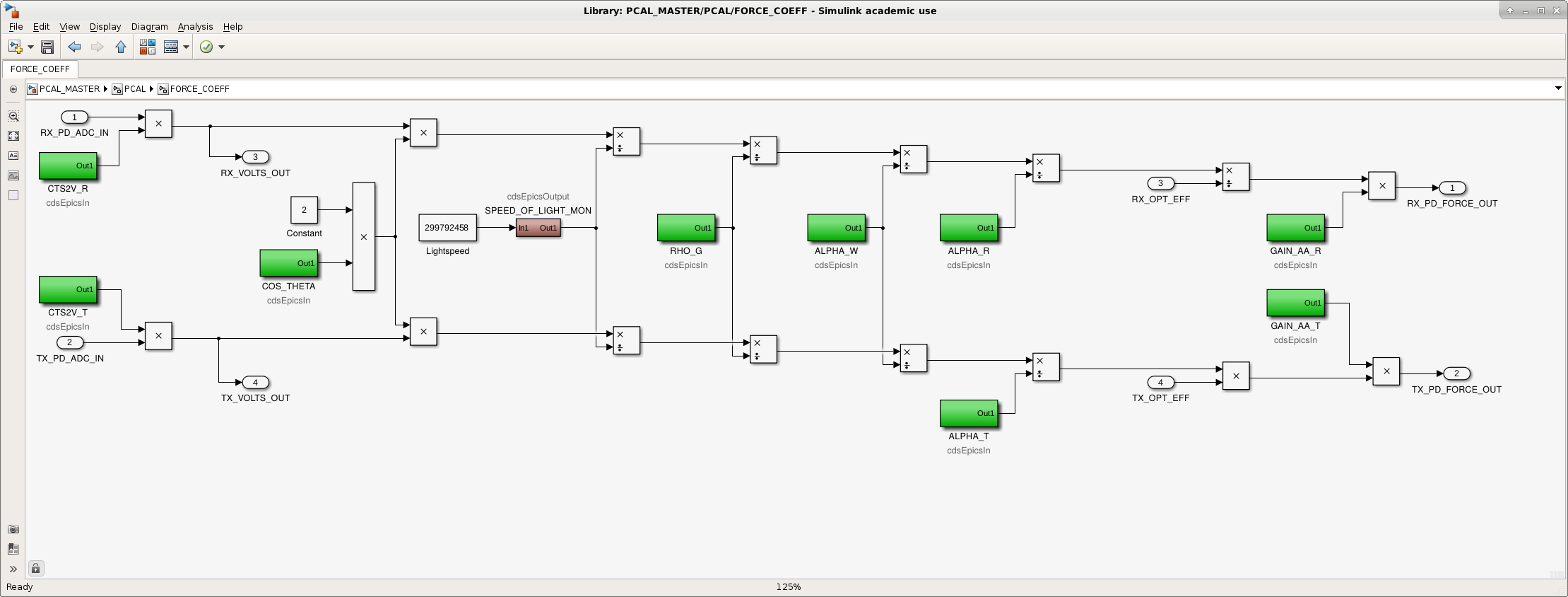
Jeff K., Evan G. ECR: E1800246 IIET: 11305, 5205 Work permit: 7850 We revised and compiled several front end models with several updates to enable compensation for time dependent interferometer parameters, and general clean-up. We list below the changes: 1) CAL-CS top level model changes: /opt/rtcds/userapps/release/cal/h1/models/h1calcs.mdl - Removed DARM_ERR_WHITENED and DARM_CTRL_WHITENED since these are no longer actually whitened and instead are double precision channels - Added an IPC receiver from each end station TX PD to the top-level CAL-CS model and piped it in to the CS library part - Added new CFTD_DELTAL channels to the frames (CFTD = compensated for time dependence) as parallel channels to the standard DELTAL channels - Deleted DARM hardware injections in top level CAL-CS. These were unused (Note removing whitened channels and DARM hardware injections saves at least five 16k channels from being saved to frames. We added only two 16k channels and four 4k channels) 2) PCAL library changes: /opt/rtcds/userapps/release/cal/common/models/PCAL_MASTER.mdl - Removed oscillator line filters because they were unused - Removed RX and TX_PD_VOLTS filters and replaced with EPICS and testpoints - Implemented computation of optical efficiencies and force coefficients as laid out in T1800046 - Allowed for different ADC gains and different analog AA filter gains because we care about this in the h(t) calibration at the <0.1% level 3) Since LHO alog 44319, we have: /opt/rtcds/userapps/release/cal/common/models/CAL_CS_MASTER.mdl /opt/rtcds/userapps/release/cal/common/models/CAL_LINE_MONITOR_MASTER.mdl - completed the front end computation of the detuned SRC spring frequency and Q (f_s and Q) because we changed the tracking of PUM and UIM stage from a common time dependent scalar to be separately tracked as two time dependent scalars - implemented parallel path calculation for on-the-fly compensation for a time-dependent cavity pole frequency - added excitation point in QUAD model parallel to the calibration lines so that we make excitations for sweeps at the same point as for the calibration lines that are injected. This allows for easier removal of time-dependent changes in actuation gains so that we can search for unknown systematic errors 4) In top level PCALEX / PCALEY model: /opt/rtcds/userapps/release/cal/h1/models/h1calex.mdl /opt/rtcds/userapps/release/cal/h1/models/h1caley.mdl - added IPC senders of TX PD signals to go to the CAL-CS model Presentation given to the calibration group (see G1801594) will be updated to reflect these changes.
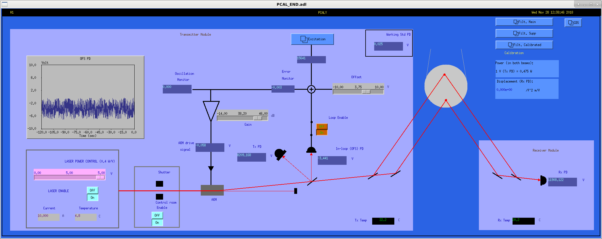
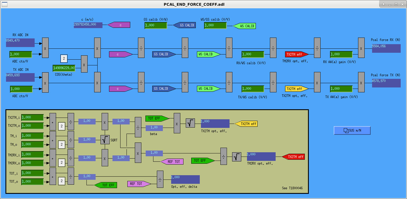
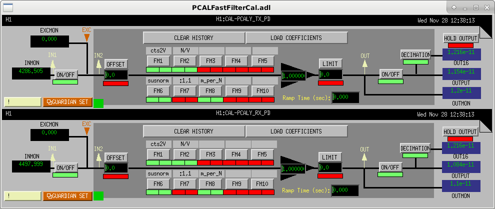
Here some screenshots of the updates to the PCAL front-end model and MEDM screens updated to more explicitly calculate the force coefficient used in the pcal system.
The screenshots of the simulink model are from the PCAL library part,
/opt/rtcds/userapps/release/cal/common/models/PCAL_MASTER.mdl
The MEDM screen for the newly explicit calculation of the force coefficient can be found from each PCAL overview screen (see 4th image), by following the "Filt. Calibrated" linked screen button (third down from the list of three linked boxes in the upper right corner). The 5th attachment is this new screen (crafted by Evan), and the former old calibration filters can be found linked from this screen in the lower right corner, labeled "SUS m/N."
These screens live in
/opt/rtcds/userapps/release/cal/common/medm/
PCAL_END.adl
PCAL_END_FORCE_COEFF.adl
PCALFastFilterCal.adl
At the moment, all of this new infrastructure is bypassed as shown in the attached screenshots. This is done by setting virtually all the new EPICs records to 1.0, and the cos( heta) term to be 1/2 * c, such that when the hard-coded speed of light is multiplied in, this previous term cancels it to be 1.0 as well. As such, the TX_PD or RX_PD filters -- which in the new scheme are intended to be only the suspension response (currently in FM6 and FM8 as "susnorm" and "m_per_N") -- still include the O2 force coefficients in FMs 1 and 2 as "cts2V" and "N/V".
This is just an alog to record the time that this happened, but when we tried to transition DRMI to 3f, the SRCL input matrix element must not have gotten written correctly, which resulted in a PRMI lock with SRM swinging. We were able to hold the PRMI lock for about 90 seconds while the SRM was flashing before PRMI broke and we reacquired regular DRMI.
What this means is that we do have a scenario and set of parameters where we should be able to use to perhaps get the PRMI to DRMI transition working again. We've been struggling since the end of O2 with this, since PRMI always seems to break lock when the SRM is brought back into alignment.
The times are roughly 1223078480 - 1223078570.
Just so no one gets worried when the open the ASC detail screens, I've created new ARM and Central ASC detail screens. There are a few white blanks right now, that will get populated with the new EPICS records from the smooth limiter, when we restart the ASC model tomorrow.
I attach a Virgo log entry I just made that compares chamber vibrations, acoustic environment, magnetic environment and 1-50 Hz seismic environments at Virgo and LHO. One of the issues at Virgo is that the HVAC drives acoustic noise at the end stations that, in the 10-30 Hz band is about 10 times greater than ours. They are concerned that the acoustic pressure fluctuations may limit A+ through Newtonian coupling. To help with attempts to reduce this noise, the log contains my rough estimates of LIGO duct air velocities and Reynolds numbers, our HVAC diagrams etc.
TITLE: 10/08 Day Shift: 15:00-23:00 UTC (08:00-16:00 PST), all times posted in UTC
STATE of H1: Commissioning
INCOMING OPERATOR: None
SHIFT SUMMARY:
Started off morning with an EY crash.
LOG:
(see attached pdf text file)
Keita, Aidan (remotely), TVo
The odd noise that has been tricking the ITMX HWS software's calculation of the spherical power seems to come from some sort of dead pixel. In the attached screenshots, the large gradient vector in the upper section comes from a place where there isn't a physical hole from the Hartmann plate which gets included in the calculation for the spherical power.
According to Aidan, Adelaide has started to develop some code that will identify dead pixels so maybe we can implement it at the sites soon. As a side note, it is unclear whether or not the tight aperture that the beam goes through will drastically affect the overall sensitivity but maybe we won't know until we try measuring the self-heating from the absorption of the IFO beam and see the overall noise in our estimates.
Correction: Adelaide has developed the code to remove dead pixels. However, this is not currently integrated into the version of the HWS code running at the sites.
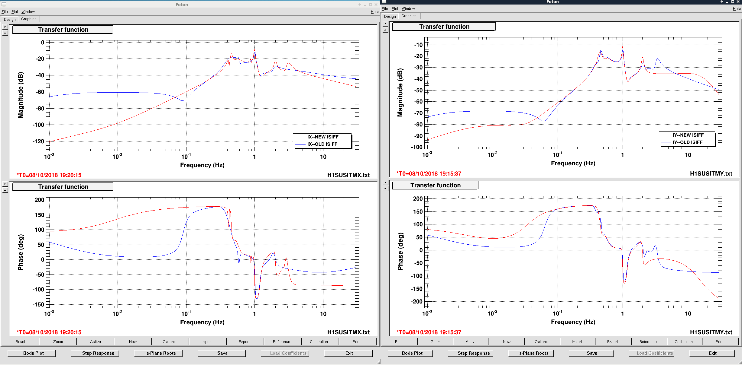
As the microseismic is back yet our recent ISIFF measurements suggested that the ITM FF filters were not working well, we updated those filters with new measurements.
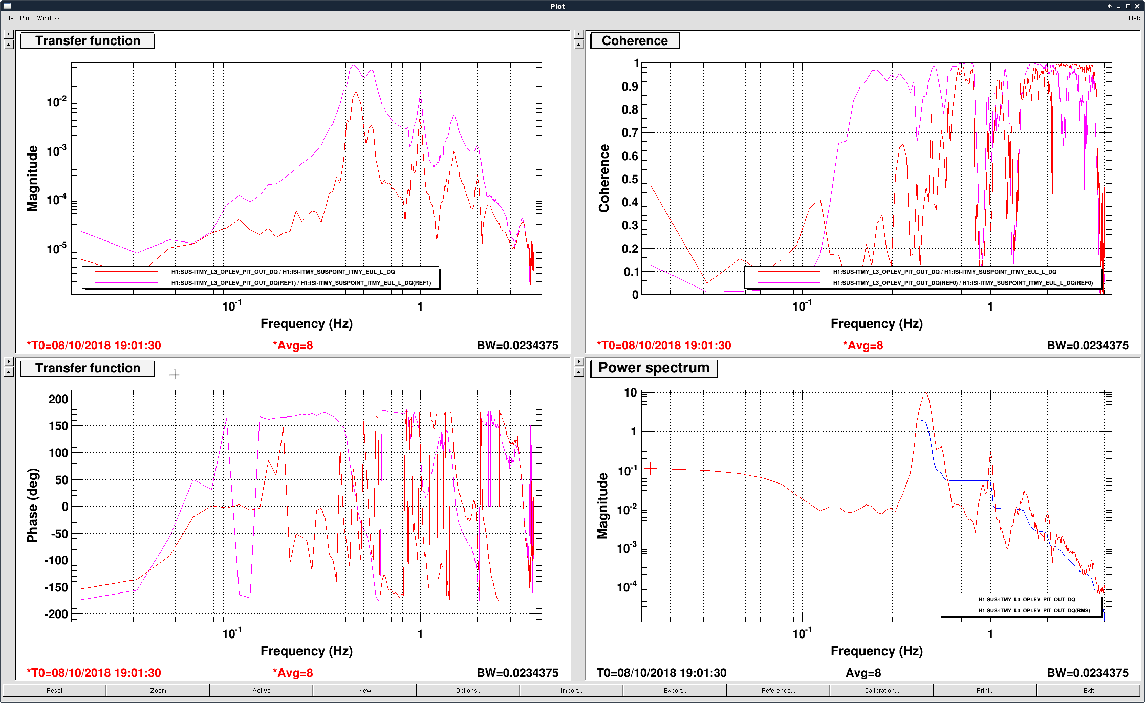
Please see the first attached figure for the filter changes. The blue traces are the old filters and the red traces are the newly designed filters. The IX filters had a bit more structures in the 0.3-1 Hz band which hopefully would improve the subtraction of ISI motion. IY stays essentially the same as the previous one in the 0.3-1 Hz band. At the same time, both filters have much smaller gains in the sub-0.1 Hz band, which should reduce the amount tilt noise injection.
In the second figure we show the oplev response to ISI sus pt L motion with (red) and without (pink) the ISIFF. We show only the result for IY because the amount of reduction in IX is similar.
Will test the new FF filters with the IFO DOF like D/CHARD loops. Will also update the ETM filters once we have time.
The End-Y safety interlock system for E-stops had a failure. This shut down the ALS and SQZ lasers. An input module that monitors the VEA Entry Estop lost one of two channels. This caused and error in the system and thus shut down teh lasers. We would have been down for an hour except we struggled getting the system back up. It appears that the module we tried to replace teh bad unit with also had trouble. This module was taken from a test stand so we are not sure of it's pedigree. We again swapped the module with a replacement and the system returned ot normal. All lasers restored by noon.
FRS 11613
Beckhoff module EL1904 was replaced. Safety System is now back up. ALS lasers at both the end stations are now on. FRS 11613 was closed.
In addition, for some reason when I rescanned the bus for the replaced module, I lost the links to the spare and squeezer interlock readbacks. I relinked them and committed the update to svn.
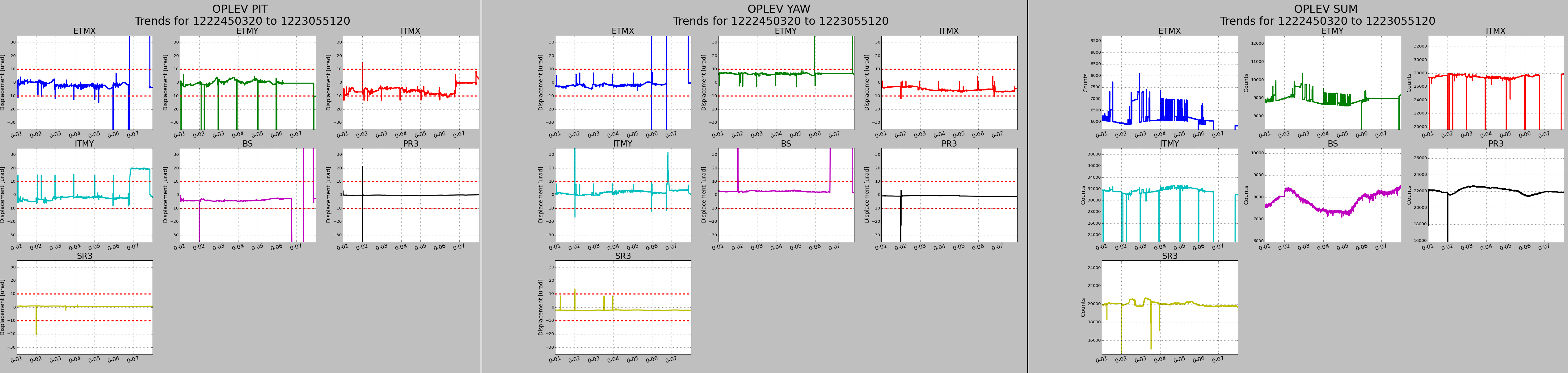
Most Oplev channels look nominal, except for ETMy looks to be pitched down (near -10), but this is probably due to the EY SUS crash over the weekend (Jenne said it should be addressed w/ Initial Alignment). Screenshot for oplev plots attached.
Time To Perform Task: 14min
TCSx: Chiller level was at "Max Level" & no water added.
TCSy: Chiller level was at 8.4cm & 1200 mL of water was added to [get] level to the "Max Level".
NOTE: I only removed the GRAY chiller cap for TCSy Chiller. I was not sure where/how to remove the mesh filter. Thomas later informed me we are supposed to remove the Chiller Cap "Panel" to gain access to this Mesh Filter. So there is a chance the level I filled to might be erroneous.
This is the first FAMIS task for the TCS chillers. TCSY was just given a marker on its water level last week (and by marker, I mean it's a ruler taped to the side of the water level). We had paper logs for these chillers on the chillers themselves, but they were never checked consistently. Enter FAMIS task. Hopefully, combined logs and consistent checks will give us quicker indicators of leaks and normal/expected water loss rates. So yeah, there is a bit of slop here that we are cleaning up :)
This seems like a large amount of water for TCSY. I have been keeping a close eye on the chillers, and the level for the Y chiller has been stable for the past few weeks. I only put the ruler on that chiller last week, so I can't say at what level it was at previously, but I would guess ~2cm below the max line. Either way, this warranted a leak check.
Jason and I walked the lines and checked on table to look for any hints of a leak and found nothing. Looking back at the chiller, the water level was a touch above max, and I could see that 1.2L could squeeze in there from the previous level. There seems to be no leak, that we could find, but we will continue to watch these chillers closely.
A couple of (maybe not so helpful) observations:
I think tightening up the procedure and sorting out the fill date tracking will help avoid confounding a leak with an accumulation of expected water loss in the future.
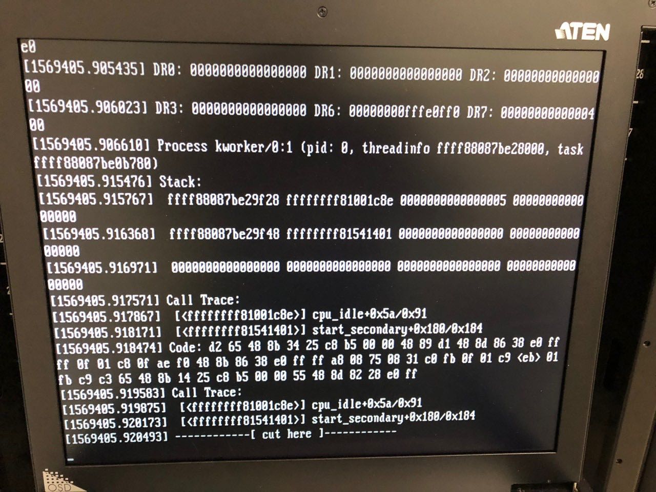
I have remotely reset the h1susey computer. Procedure was: disable the Dolphin IXS600 port h1susey is connected to and then issue a 'chassis power reset' command via the remote management IPMI port.
The whole process only took about 5 minute to complete, so I was surprised to see the SWWD on SEI-EY had tripped (should take 10 mins to trip). Perhaps this was tripped before the reset?
h1susey console before reboot
FRS ticket 11611.
The reboot of the h1susey computer to the point where the h1iopsusey model was running again took over 5 minutes, which caused the software-watchdogs on the seismic system (h1iopseiey) to trip, which in turn zeroed all the DAC drives for this front end.
We should perhaps reconsider the SWWD receivers on h1iopseiey. Two options are:
This is a late alog of work done yesterday afternoon with Gabriele.
Friday evening Daniel and I noticed that we have about 10 times more power on our REFL diodes than in O2 according to the readbacks, with 1mW on the in vac REFL LSC diode when we are locked at DC readout. Yesterday we tried to check that the amount of DC power roughly makes sense, which it does. Since this is one thing that is different than O2, we suspected it could be contributing to our fast lockloss problems.
The amount of power on the diodes:
There is a factor of 2 missing in the calibration for REFLAIR A, and an ND filter which attenuates the light by half. While we were sitting at DC readout with 2W of input power and a recycling gain of 48, I measured 0.54mW of light heading towards the REFL air A diode, before the ND 0.3 filter which is mounted on the diode face. That means that there should be 0.54*10^-0.3 = 0.27mW on the diode if the entire beam hits the diode and the ND filter is accurate. Our readback says that there is 0.145mW on the diode, so there is a factor of 2 missing. I also checked the centering of REFLAIR A, and noticed that we are overfilling the diode. I didn't check the calibration for REFLAIR B but there may also be a missing factor there.
The two LSC REFL air diodes should each have half as much power incident on them as the in vacuum diode does, if there were no ND filter on REFLAIR A. (see ISCT1 drawing and HAM1) This means that the measurement of 0.54mW heading towards REFLAIR A is consistent with the 1mW readback of REFL_A with 2W locked interferometer.
In O2 we had 1.8mW on LSC refl with 30W input and a PR gain of 29.5. Now with 2W of input power and a recycling gain of 48, we have 1 mW on the refl diode according to it's readback, which means we have ten times more power on the diode with the improved recycling gain for the same input power. Hang did a quick calculation for the increase in carrier power that we expect based on the improved recycling gain, 44370, and it seems plausible that we could have a factor of 10 more carrier light for the same input power with our improved recycling gain.
We are now powering up with nearly twice as much 9MHz modulation depth as we used in O2. (The 9MHz modulation depth was only slightly reduced by the EOM swap 41435 (for 45 see 41889 )) In O2 we reduced the 9MHz modulation depth by 6dB before powering up, I believe that the morning crew tried to do this in the last half of this week but it unlocked the interferometer.
As a quick test yesterday afternoon Gabriele and I switched the CARM control from REFL to REFLAIR, since it has a fourth of the amount of light that in vac REFL has.
Ideas for things to try next:
We definitely need to fix the fast locklosses, but I think that the 45MHz is important to look at as well.
We have never reduced the 9MHz before power-up. It is the 45MHz that we reduced by 3dB before power-up. In O2, the 9MHz was reduced by 6dB after we've transitioned to the low noise ESD at high power. So, we should look at both the 9 and the 45, just in case it's the 45 causing weird saturations and weird behavior in the REFL diodes, even though it's the 9 that we use for CARM control.
It's this 45MHz reduction state that I tried last week, and it failed and caused a lockloss, although I have not yet determined why.
Reflected power on lock is around 6.5% of unlocked power.
9MHz sideband power on input light is 1.8% (Γ~0.191); most of it will show up in reflection.
45MHz sideband power on input light is 3.3% (Γ~0.251); around half will show up in reflection.
So, the reflected sideband power is around 3.5%.
Sheila, Hang
In our previous calculation LHO:44370 we only kept tracking the carrier field. As Daniel pointed out, the sidebands also contributed a significant amount of power in the REFL port. Thus we updated our calculation to include the RF sidebands.
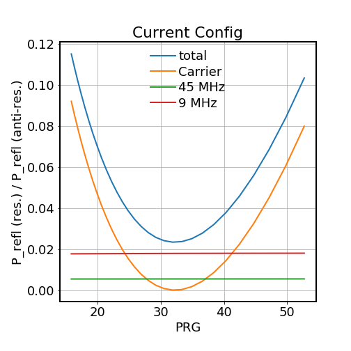
In the first figure we show the locked / unlocked refl power as a function of PRG for the current configuration, and the second plot for the O2 configuration (9 MHz mod depth is about a factor of 2 lower than current setup).
It seems that the measured result is consistent with the theoretical model prediction. For now P_refl (resonance) / P_refl (off) = 6.5% corresponds to a PRG of ~ 46.5, consistent with our measured PRG of 48.
For O2 w/ PRG of ~ 30 and 6 dB lower 9 MHz mod depth, we should expect P_refl (resonance) / P_refl(off) ~ 1%, also consistent with the measured value.
Also for the 45 MHz, we found that about 20 % of the power is reflected and 80 % transmitted, thus its contribution to the REFL port is more like 0.5%.
The code for doing the calculation is available at /ligo/home/hang.yu/Desktop/pyComm/refl_vs_trans.ipynb
I discovered that I had a typo in the reduce modulation depth states, which are a remnant from when I cleaned up all of the guardian code a few months ago. Instead of setting some TRAMP values to 30 seconds in preparation for increasing digital PD gains to compensate for lowering the modulation depth, I was setting the PD GAIN values to 30 (they should be order 1, not 30).
This is now fixed in both the 45 MHz and 9 MHz states, and loaded.