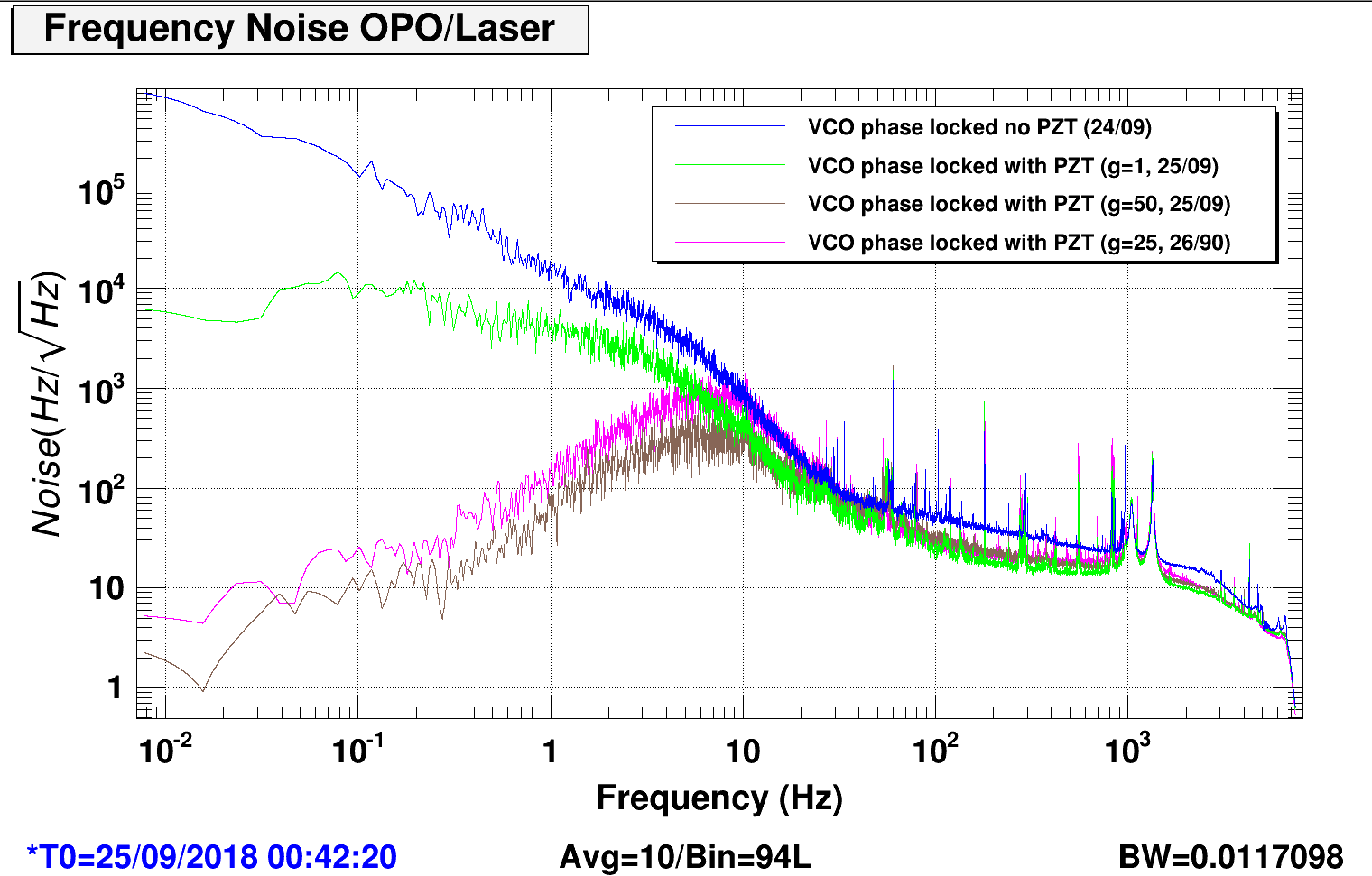
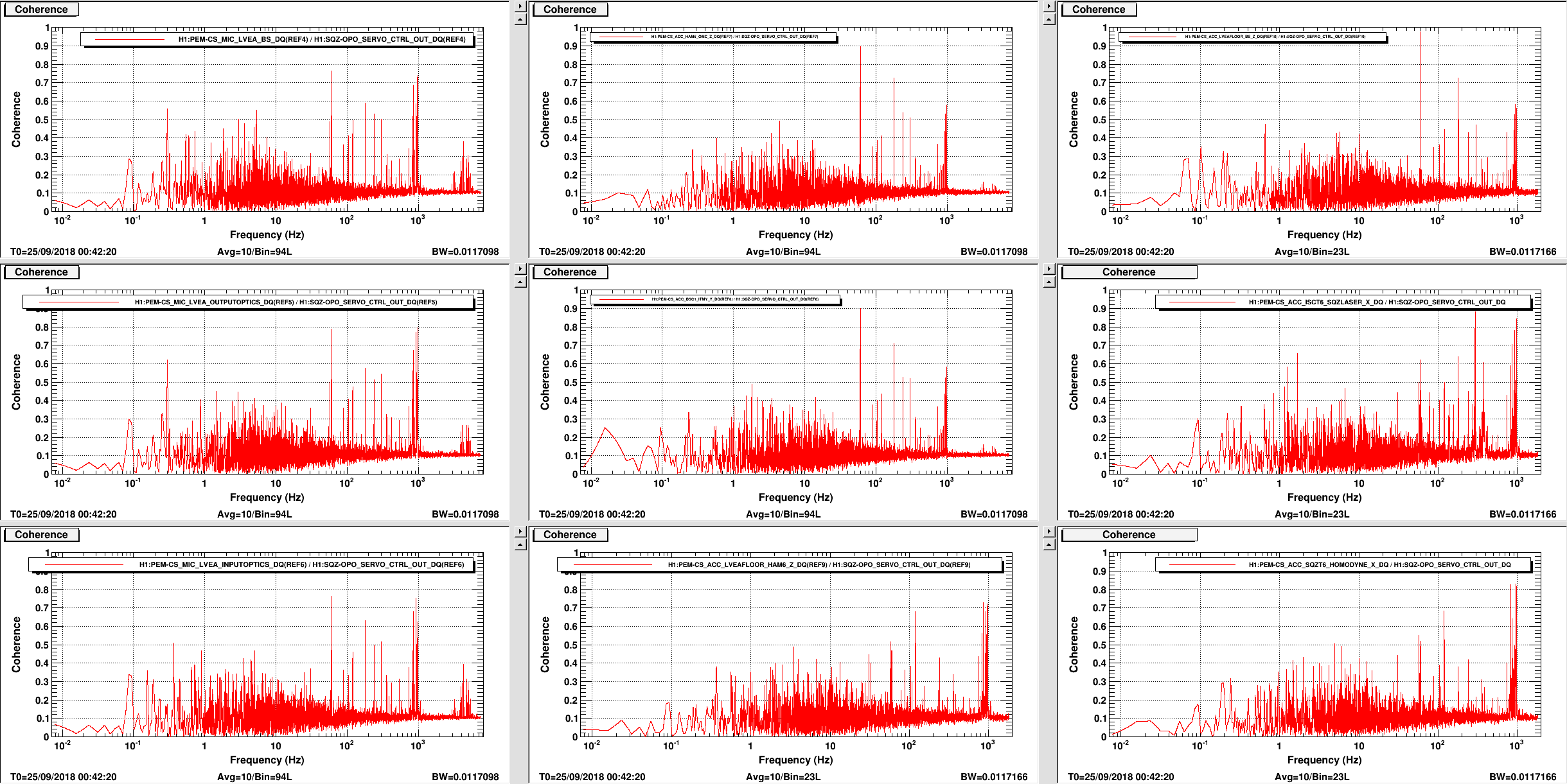
After a quick coherent hunt between OPO frequency noise and PEM channels it seems that a lot of noise came from SQZT6 and ISCT6 table (2nd and 3rd row, 3rd column). Both ISCT6 and SQZT6 accelerometer shows highest coherence at ~1kHz compared to accelerometers and microphones everywhere else in the LVEA (along PSL fiber path). ISCT6 accelerometer also shows high coherence at ~300Hz (2nd row, 3rd column). Still unclear where the noise comes from, but it's probably safe to assume that whatever noise is giving us trouble they're all local to HAM6 area.
For future reference: attached a sweep sine of CHARD yaw including the coupling to all other yaw degrees of freedom. Apart from DHARD, all other error signals see the excitation quite well.
Time To Perform Task: 14min
TCSx: Chiller level was at "Max Level" & no water added.
TCSy: Chiller level was at 8.4cm & 1200 mL of water was added to [get] level to the "Max Level".
NOTE: I only removed the GRAY chiller cap for TCSy Chiller. I was not sure where/how to remove the mesh filter. Thomas later informed me we are supposed to remove the Chiller Cap "Panel" to gain access to this Mesh Filter. So there is a chance the level I filled to might be erroneous.
This is the first FAMIS task for the TCS chillers. TCSY was just given a marker on its water level last week (and by marker, I mean it's a ruler taped to the side of the water level). We had paper logs for these chillers on the chillers themselves, but they were never checked consistently. Enter FAMIS task. Hopefully, combined logs and consistent checks will give us quicker indicators of leaks and normal/expected water loss rates. So yeah, there is a bit of slop here that we are cleaning up :)
This seems like a large amount of water for TCSY. I have been keeping a close eye on the chillers, and the level for the Y chiller has been stable for the past few weeks. I only put the ruler on that chiller last week, so I can't say at what level it was at previously, but I would guess ~2cm below the max line. Either way, this warranted a leak check.
Jason and I walked the lines and checked on table to look for any hints of a leak and found nothing. Looking back at the chiller, the water level was a touch above max, and I could see that 1.2L could squeeze in there from the previous level. There seems to be no leak, that we could find, but we will continue to watch these chillers closely.
A couple of (maybe not so helpful) observations:
I think tightening up the procedure and sorting out the fill date tracking will help avoid confounding a leak with an accumulation of expected water loss in the future.
Laser Status:
Front End Power is 33.3W (should be around 30 W)
70W Output Power is 75.75W
Front End Watch is GREEN
70W Watch is GREEN
PMC:
It has been locked 2 days, 1 hr 6 minutes (should be days/weeks)
Reflected power = 17.14Watts
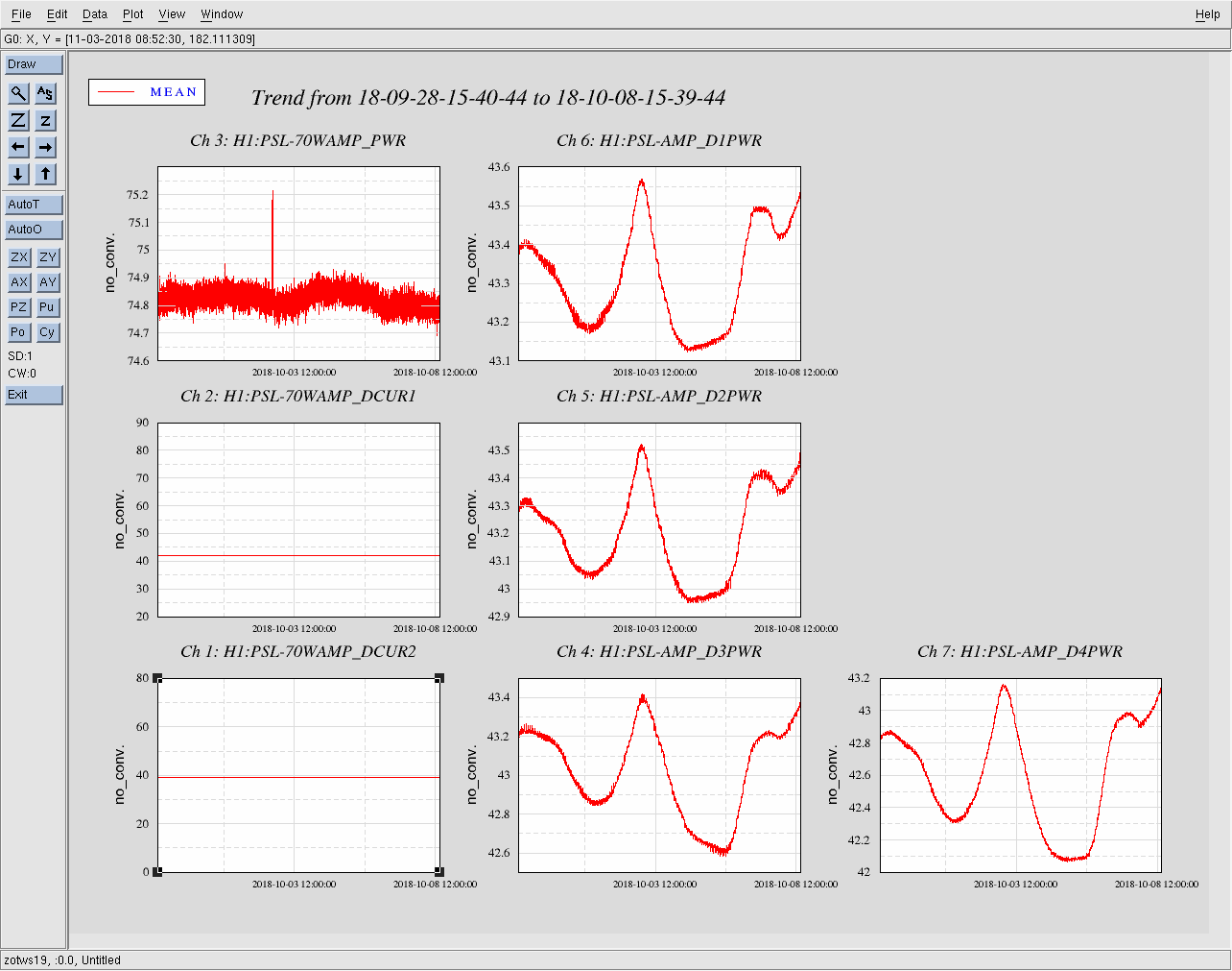
Transmitted power = 43.5Watts
PowerSum = 60.64Watts.
FSS:
It has been locked for 0 days 21 hr and 15 min (should be days/weeks)
TPD[V] = 2.075V (min 0.9V)
ISS:
The diffracted power is around 1.6%
Last saturation event was 2 days 1 hours and 6 minutes ago (should be days/weeks)
Discussed CDS crashes from the weekend (due to recent upgrad).
Talking about Maintenance
General Coordination Tasks
(Hang, Corey)
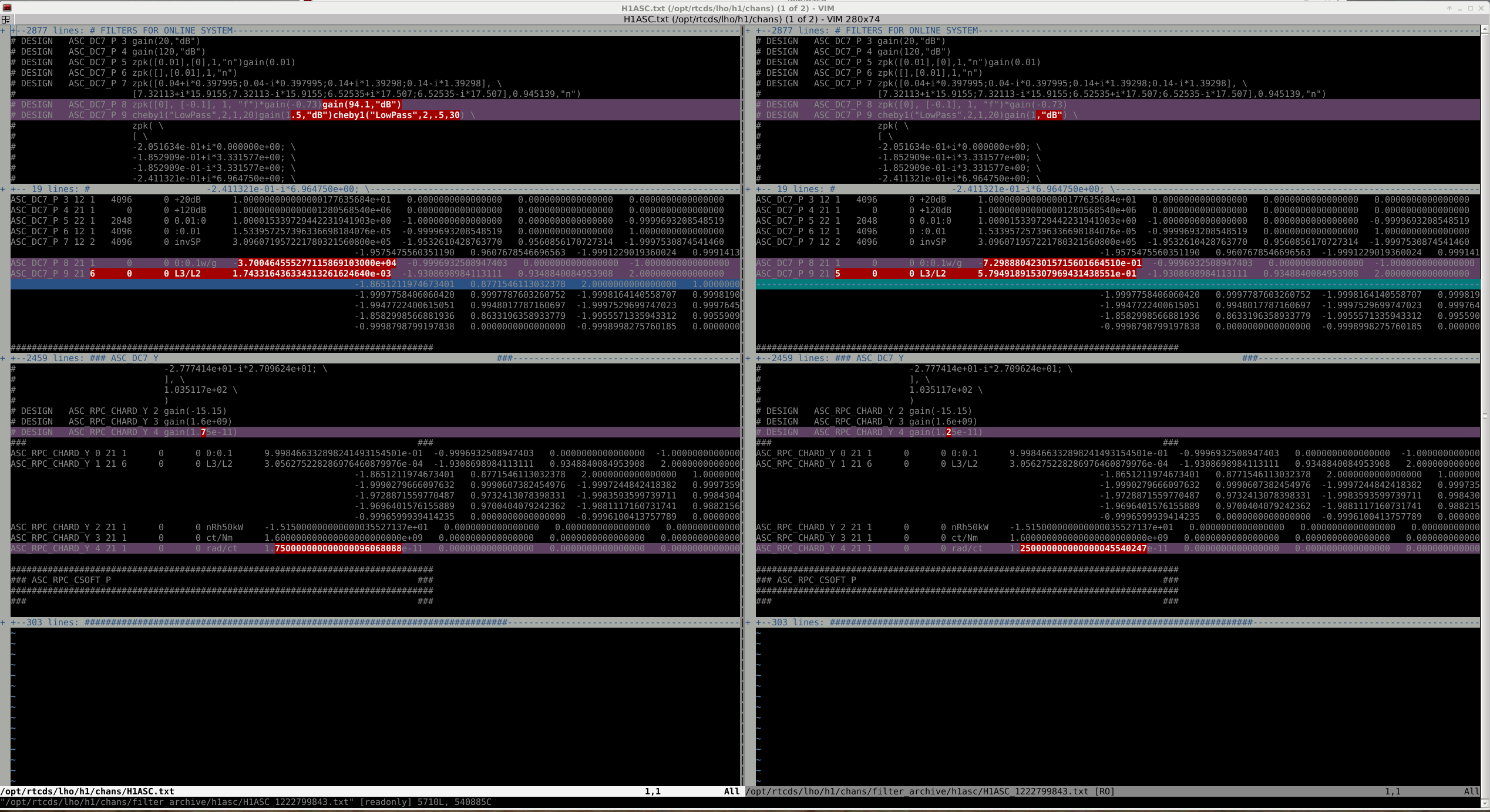
Ran through the Operator Check Sheet's CFC (Configuration File Change) Check. h1asc was the one model which had a CFC Warning (red box on CDS Overview medm). Ran the command "filter_diffs asc", and had a few diffs which came up (see attached output screenshot) related to Radiation Pressure Compensation (RPC) filter banks (as well as some "unused" filter banks, i.e. ASC_DC7_P). Since this was probably commissioning-related, I grabbed Jenne to ask about the diffs, and she steered me to Hang. Hang confirmed these were changes he did, and so we hit the Load Coefficients for this model (@16:39utc and this cleared the CFC Warning).
All looks nominal
TITLE: 10/08 Day Shift: 15:00-23:00 UTC (08:00-16:00 PST), all times posted in UTC
STATE of H1: Commissioning
OUTGOING OPERATOR: None
CURRENT ENVIRONMENT:
Wind: 0mph Gusts, 0mph 5min avg
Primary useism: 0.02 μm/s
Secondary useism: 0.20 μm/s
QUICK SUMMARY:
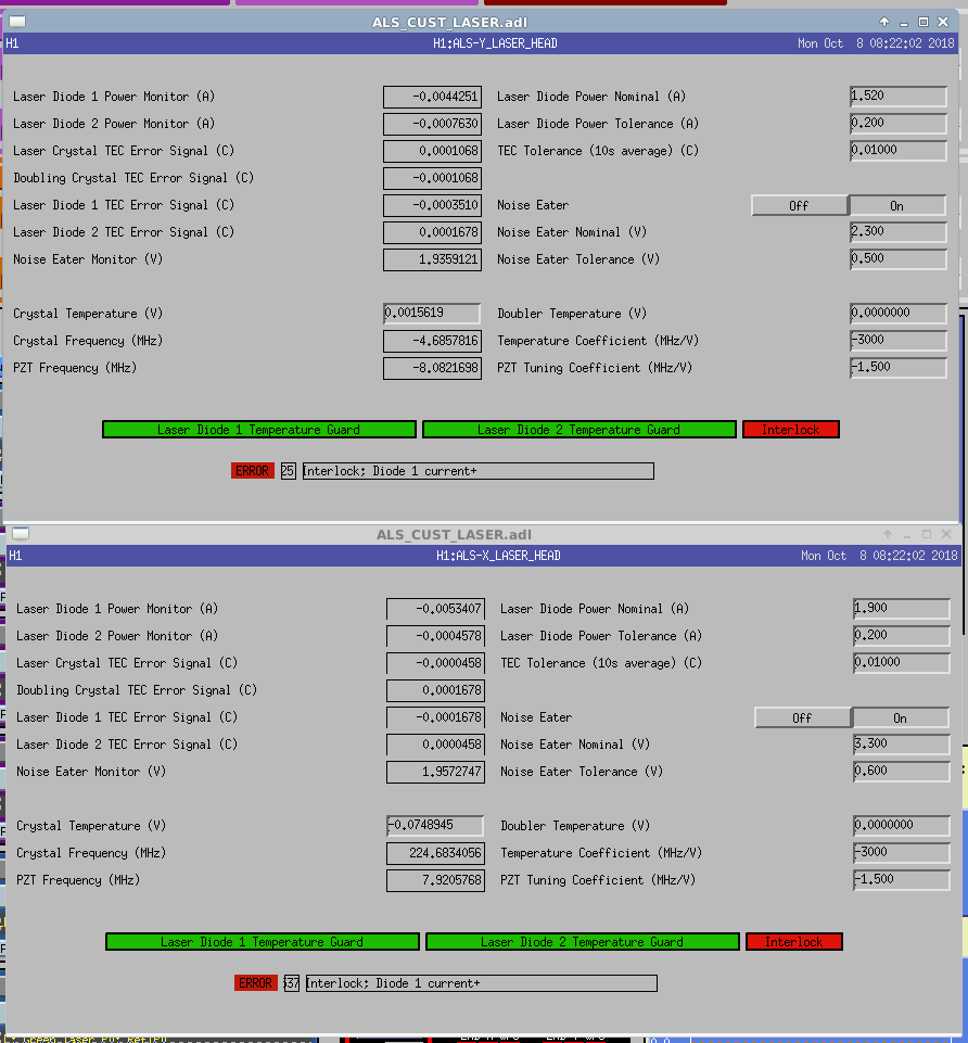
Both ALS lasers are off. It looks like they both think their interlocks were triggered / tripped?
I have remotely reset the h1susey computer. Procedure was: disable the Dolphin IXS600 port h1susey is connected to and then issue a 'chassis power reset' command via the remote management IPMI port.
The whole process only took about 5 minute to complete, so I was surprised to see the SWWD on SEI-EY had tripped (should take 10 mins to trip). Perhaps this was tripped before the reset?
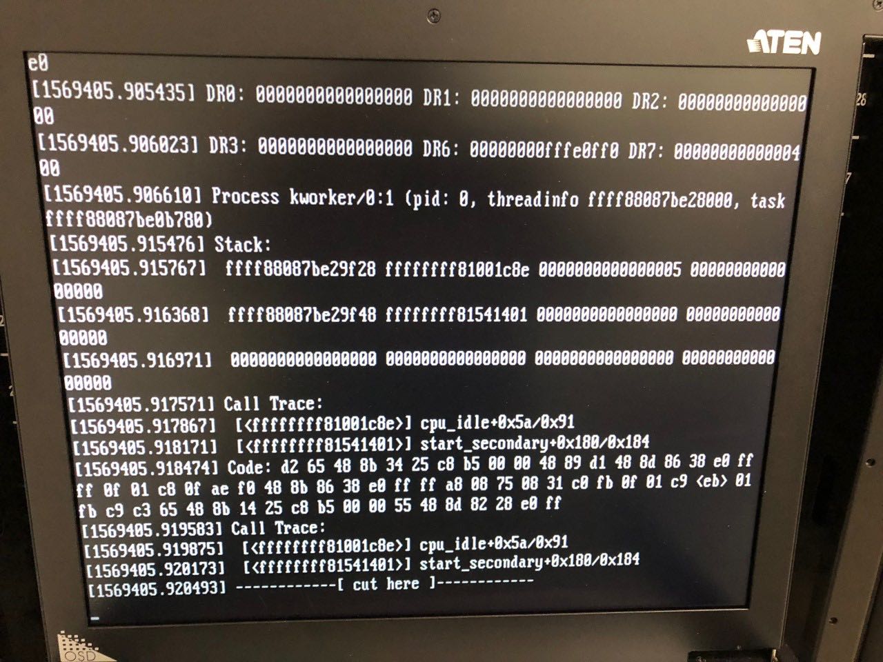
h1susey console before reboot
FRS ticket 11611.
The reboot of the h1susey computer to the point where the h1iopsusey model was running again took over 5 minutes, which caused the software-watchdogs on the seismic system (h1iopseiey) to trip, which in turn zeroed all the DAC drives for this front end.
We should perhaps reconsider the SWWD receivers on h1iopseiey. Two options are:
I walked into the control room this morning to a symphony of names of optics being announced on the verbal saturation alarm. The ISC_LOCK guardian had connection errors, and so was not able to recognize the fact that the lock was lost, so it had not run the DOWN state. I stopped and restarted the ISC_LOCK guardian, which cleared the error long enough for it to start the DOWN state.
While the DOWN state was resetting things, I checked the alog and see that Jamie predicted this behavior in alog 44383, since a similar thing happened at LLO recently.
I think the take-away here is that if a front end computer has crashed, we should ensure that the IFO is in its DOWN state. (To do this, in ISC_LOCK guardian, request 'manual' control, then select DOWN, then request 'auto' control. You may also have to ask the node to STOP (pulldown menu that is usually on EXEC), then request EXEC again.) I'm happy to receive a call to do this remotely if someone is busy with other recovery.
Carlos and DaveB are already working on recovery of the susetmy computer.
This is a late alog of work done yesterday afternoon with Gabriele.
Friday evening Daniel and I noticed that we have about 10 times more power on our REFL diodes than in O2 according to the readbacks, with 1mW on the in vac REFL LSC diode when we are locked at DC readout. Yesterday we tried to check that the amount of DC power roughly makes sense, which it does. Since this is one thing that is different than O2, we suspected it could be contributing to our fast lockloss problems.
The amount of power on the diodes:
There is a factor of 2 missing in the calibration for REFLAIR A, and an ND filter which attenuates the light by half. While we were sitting at DC readout with 2W of input power and a recycling gain of 48, I measured 0.54mW of light heading towards the REFL air A diode, before the ND 0.3 filter which is mounted on the diode face. That means that there should be 0.54*10^-0.3 = 0.27mW on the diode if the entire beam hits the diode and the ND filter is accurate. Our readback says that there is 0.145mW on the diode, so there is a factor of 2 missing. I also checked the centering of REFLAIR A, and noticed that we are overfilling the diode. I didn't check the calibration for REFLAIR B but there may also be a missing factor there.
The two LSC REFL air diodes should each have half as much power incident on them as the in vacuum diode does, if there were no ND filter on REFLAIR A. (see ISCT1 drawing and HAM1) This means that the measurement of 0.54mW heading towards REFLAIR A is consistent with the 1mW readback of REFL_A with 2W locked interferometer.
In O2 we had 1.8mW on LSC refl with 30W input and a PR gain of 29.5. Now with 2W of input power and a recycling gain of 48, we have 1 mW on the refl diode according to it's readback, which means we have ten times more power on the diode with the improved recycling gain for the same input power. Hang did a quick calculation for the increase in carrier power that we expect based on the improved recycling gain, 44370, and it seems plausible that we could have a factor of 10 more carrier light for the same input power with our improved recycling gain.
We are now powering up with nearly twice as much 9MHz modulation depth as we used in O2. (The 9MHz modulation depth was only slightly reduced by the EOM swap 41435 (for 45 see 41889 )) In O2 we reduced the 9MHz modulation depth by 6dB before powering up, I believe that the morning crew tried to do this in the last half of this week but it unlocked the interferometer.
As a quick test yesterday afternoon Gabriele and I switched the CARM control from REFL to REFLAIR, since it has a fourth of the amount of light that in vac REFL has.
Ideas for things to try next:
We definitely need to fix the fast locklosses, but I think that the 45MHz is important to look at as well.
We have never reduced the 9MHz before power-up. It is the 45MHz that we reduced by 3dB before power-up. In O2, the 9MHz was reduced by 6dB after we've transitioned to the low noise ESD at high power. So, we should look at both the 9 and the 45, just in case it's the 45 causing weird saturations and weird behavior in the REFL diodes, even though it's the 9 that we use for CARM control.
It's this 45MHz reduction state that I tried last week, and it failed and caused a lockloss, although I have not yet determined why.
Reflected power on lock is around 6.5% of unlocked power.
9MHz sideband power on input light is 1.8% (Γ~0.191); most of it will show up in reflection.
45MHz sideband power on input light is 3.3% (Γ~0.251); around half will show up in reflection.
So, the reflected sideband power is around 3.5%.
Sheila, Hang
In our previous calculation LHO:44370 we only kept tracking the carrier field. As Daniel pointed out, the sidebands also contributed a significant amount of power in the REFL port. Thus we updated our calculation to include the RF sidebands.
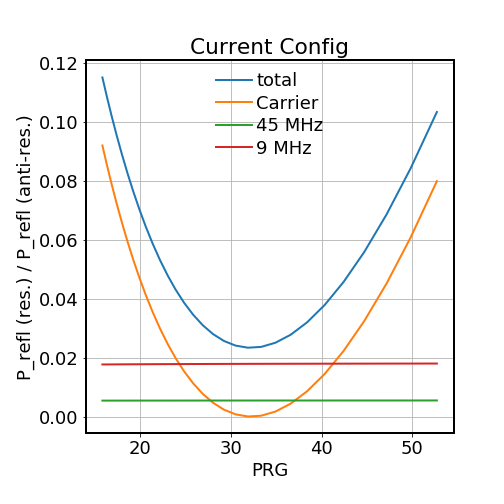
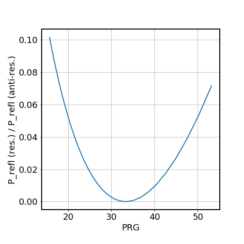
In the first figure we show the locked / unlocked refl power as a function of PRG for the current configuration, and the second plot for the O2 configuration (9 MHz mod depth is about a factor of 2 lower than current setup).
It seems that the measured result is consistent with the theoretical model prediction. For now P_refl (resonance) / P_refl (off) = 6.5% corresponds to a PRG of ~ 46.5, consistent with our measured PRG of 48.
For O2 w/ PRG of ~ 30 and 6 dB lower 9 MHz mod depth, we should expect P_refl (resonance) / P_refl(off) ~ 1%, also consistent with the measured value.
Also for the 45 MHz, we found that about 20 % of the power is reflected and 80 % transmitted, thus its contribution to the REFL port is more like 0.5%.
The code for doing the calculation is available at /ligo/home/hang.yu/Desktop/pyComm/refl_vs_trans.ipynb
I discovered that I had a typo in the reduce modulation depth states, which are a remnant from when I cleaned up all of the guardian code a few months ago. Instead of setting some TRAMP values to 30 seconds in preparation for increasing digital PD gains to compensate for lowering the modulation depth, I was setting the PD GAIN values to 30 (they should be order 1, not 30).
This is now fixed in both the 45 MHz and 9 MHz states, and loaded.
h1susey has crashed. Similar to h1lsc0 this morning it looks like the models are still running and the suspensions are still being damped. We have lost DAQ data from this machine and EPICS monitoring/controls.
If we need to restart this system, please call me on my cell phone and I can do this remotely.
h1susey crashed at 19:00 PDT (02:00 Sun 7th UTC).
current status of SUS-EY.
I spoke with Richard on the phone last night soon after the crash and we agreed we could leave this system overnight because both the software-watchdog (running on h1iopsusey) and the independent hardware-watchdogs were functioning.
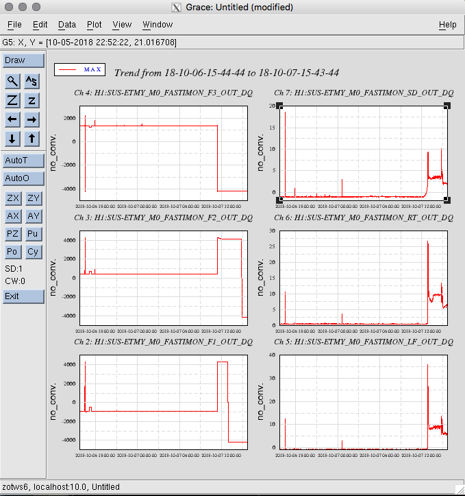
I realized we can indirectly monitor what the h1susetmy model is doing by looking at the coil current monitors being acquired by the h1susauxey model. Attached plots show 24 hours of M0_F1 IMON against h1susetmy_cpu_meter, 7 days of M0_F1_IMON, and 24 hours of all the ETMY M0 IMONs.
It looks like the suspension has changed state around 4am this morning.
Would the first commissioner on site today please call me on my cell phone and we can schedule a restart of h1susey.
You have to be careful leaving the front end in this state, at least when it come to guardian. If a guardian node can't see EPICS channels it needs it goes into a CERROR state, in which it won't progress on it's graph until the needed channels are recovered.
We had a very similar failure at LLO last week, while the IFO was at full lock. The IFO kept operating otherwise normally, but the ISC_LOCK node went into CERROR. When there was a lockloss the node was still stuck and the DOWN state was not executed. This can be bad since certain resets don't take place in a timely manner, which can cause things like violin modes to et rung up.
Looks like that's exactly what happened here. See alog 44384 for a few notes.
In the attached plot we show the refl pd power as a function of power recycling gain (PRG). Here the x-axis is the PRG, the y-axis is the refl PD power, normalized by the power when the carrier is anti-resonant in CARM & PRC. In generating the plot we vary the arm losses as a parameter to compute the PRG and refl power simultaneously.
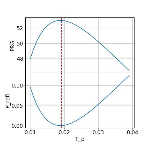
Daniel suggested that in the future we might consider changing the PRM transmissivity to optimize the power recycling gain (PRG), given that we have less losses in the arms.
In the attached figure we show the PRG and reflected power P_refl (normalized by the anti res value) as a function of the PRM transmissivity. In the calculation we have assumed a total loss in one arm is 67 ppm (55 ppm loss at the ITM, 8 ppm scattering loss at the ETM, and 4 ppm transmissivity of the ETM), which gives a PRG of 50 for the current PRM transmissivity of 0.03. The red-dashed line shows the theoretically expected optimal T_prm that maximizes the recycling gain, and can be calculated based on the simple relation (cf. eq. 2.18 of Evan Hall's thesis, assuming T_itm=0.014):
T_prm (optimal) = 4 eta_arm / T_itm = 1.91% * (eta_arm / 67 ppm),
where eta_arm is the total loss per arm. This leads to an optimal recycling gain of
PRG (optimal) = T_itm / (4 * eta_arm) = 52.2 * (67 ppm / eta_arm).
The figure shows spectra from the 4 angular IMC WFS DC channels with labeled peaks. Eight of the peaks between 80 and 1000 Hz are from optics or structures on the PSL table, two were from IOT2 and four haven’t been identified. The unidentified peaks were not excited by our PSL injections, even the global ones. It is possible that they are associated with structures that weren’t excited on IOT2 or in HAM2, or they may be associated with structures on the PSL table that we weren’t able to excite.
The identified sources are table resonances, periscope resonances and optic mount resonances. All optics that produced peaks in the spectrum were downstream of the PMC and were mirrors rather than through-optics like lenses, as would be expected.
The figure also shows the location of the sources in the PSL, as well as samples of the bowing and tapping data used to make the identifications.
Robert, Craig
This version of the jitter spectrum includes photos of the optics. It should be easy to lower the Q of some of the higher-Q optics like M3.
This is a very interesting and impactful glimpse into the current state of PSL table jitter coupling. Wish I had noted the study on first release.
I'm sure many would be interested in seeing an equivalent study of LLO, in everyone's spare time
.
This study is relevant to IIET Ticket 4639 with title: "ECR: Modify attachment of optics mount to mounting plate on PSL periscope, previously Bug 1140". This IIET Ticket corresponds to the upper periscope mirror mount, with designator IO_MB_M6.
This study is relevant to IIET Ticket 5132 with title: "Move IO input beam PZT-mount from periscope to PSL/IO table surface". This IIET Ticket corresponds to the steering mirror upstream of the periscope which has a PZT actuator, with designator IO_MB_M4.
This effort was subsequently re-examined by Robert in
https://alog.ligo-wa.caltech.edu/aLOG/index.php?callRep=44460