TITLE: 06/19 Day Shift: 15:00-23:00 UTC (08:00-16:00 PST), all times posted in UTC
STATE of H1: Commissioning
INCOMING OPERATOR: None
SHIFT SUMMARY:
PSL has been down for most of the day, but...
PSL is on its way up currently (Jason & Peter currently working on it.)
Once beam is back, Commissioning Team will transition the LVEA back to Laser HAZARD tonight (WP#7661).
LOG:
(Continuing From 18:45utc after getting hand off from Ed)
Also, shut down the remaining Clean Room circuit that had been left on for lighting.
At some point before lunch today, I connected and started a small turbo backed by an aux. cart at the cross connected to CP1's 10" gate valve. There is a dry nitrogen gas connection at a tee at the turbo inlet and I am letting the turbo pump against the closed 1 1/2" AMV mounted to one of the cross' ports. Tomorrow, I will valve-in the turbo to the cross and then admit dry nitrogen at the turbo inlet to test if the 10" gate valve leaks into CP1. If no leaks into CP1 are observed, I will let the turbo spin down while letting the cross completely vent with the nitrogen. The small turbo will then be valved-out. Next, the cross' 8" CFF blank will be removed and a maglev turbo (backed by a leak detector) will be installed in its place and spun up.
This arrangement will then be left pumping against the closed 10" gate valve until we can get time to continue hunting for the leak that is known to exist somewhere around CP1 and GV6.
WP 7658, E1700370, T1700433 Filiberto, Patrick We have completed the initial changes to the EtherCAT network topology. There are now six EtherCAT devices: MSR Auxiliary, Vertex Auxiliary, Vertex Squeezer, Vertex ISC, EndX and EndY. MSR Auxiliary is the single chassis in the MSR. This chassis used to supply the fiber connections to the set of ISC chassis in the CER and to the end stations. These fiber connections are now on separate devices (Vertex ISC, EndX and EndY) that interface through the new media converter chassis in the MSR. The copper connection from the computer to the MSR Auxiliary chassis remains unchanged. Vertex Auxiliary is the EtherCAT hub in the LVEA which connects to the illuminators and serial readback of the TCS chillers. Vertex Auxiliary and Vertex Squeezer were previously and remain on separate devices. They are also now interfaced to through the new media converter chassis. The PSL and TCS set of chassis will later be given their own single device and moved off of the Vertex ISC device. They will also be interfaced to through the new media converter chassis. The connection to the baffle photodiodes will later be moved from the Vertex ISC device to the Vertex Auxiliary device. Daniel previously made a new TwinCAT system manager in preparation for this work. The only issue I had was that I was not able to see any terminals when I used it to scan the MSR Auxiliary device. I was able to remedy this by changing the NetId of this device from 10.40.10.1.1.1 to 10.40.10.1.4.1. After this everything worked very smoothly.
The front end laser control box was modified to allow remote activation of the NPRO's noise eater. In addition the NPRO power supply was modified to accommodate this change. Fil / Peter
Beckhoff Slow Controls
Daniel, Patrick, Dave:
New configurations for h1ecatc1plc1, h1ecatx1plc2 and h1ecaty1plc2 had accrued over the past week and were installed into CDS today. New INI files were read by the DAQ, new autoBurt.req files were installed in the target area, new SDF-monitor files are being used, new safe.snap files were generated by blanket monitor-acceptance of new channels.
WP7651 BLRMS added to ISI ETMX and ETMY
Jim, Dave
New h1isietm[x,y] models were installed to add BLRMS calcuations. DAQ restart was required.
PSL ISS binary code fix
Keita, Dave:
A new h1psliss model was restarted to fix bio issues. No DAQ restart was needed.
Changed cell phone alarms password
Ryan, Dave:
The password used by the cell phone alarms system was changed and the software was restarted.
Georgia, Sheila
I have run a script that dithers the test mass ESD in pitch and yaw, in combinations with and without signal and bias offsets, and looks at the coupling to the optical lever to measure three combinations of the four force co-efficients (alpha, beta, beta_2, and gamma).
I take the transfer functions from pitch, yaw, and bias drive (at a single drive frequency) to pitch and yaw on the optical lever, use the sus model to convert this to Newtons of force on the test mass per volt of ESD drive, and calculate the parameters from this. This follows a similar method to Sheila’s in-lock charge measurements (see alog 38387 and 38608), but looking at the oplev signal rather than DARM.
The parameters I’ve measured on ETMX are
| pit | yaw | |
| alpha [N/V^2] | 4.0e-9 | 3.7e-9 |
| beta-beta2 [N/V] | 2.0e-7 | 1.2e-7 |
| gamma [N/V^2] | -4.0e-9 | -3.6e-10 |
| V_eff [V] | 12.6 | 8.5 |
The numbers I calculate for Veff roughly agree with the usual Kissel-style V_eff measurement, the latest results from this I’ll post first thing tomorrow. For some reason I am still trying to pin down these are all off by an order of magnitude compared to the values of alpha, gamma and beta-beta2. I also might have lost track of signs somewhere.
The force on the test mass as a function of bias and signal (ESD electrode) voltages is given by:
.
For longitudinal measurements, we could drive bias voltage while changing the offset on the bias. To determine these parameters in pitch and yaw we need to always either drive or offset the signal, as the bias cannot be varied quadrant by quadrant. Hence in this type of measurement we can only determine alpha, gamma, and beta - beta_2.
Driving the bias, with offsets in either the bias or signal, the force on the test mass linear with the drive, , is:
.
Driving the signal, with offsets in either the bias or signal, the force on the test mass linear with the drive, is:
.
The measurements required to calculate alpha, beta-beta2, and gamma are:
1.Drive signal, no signal or bias offsets , which applies a force on the test mass:
.
2.Drive signal, with a signal offset
My log post keeps getting cut off so it continues here:
Maintenance Day
15:05 Ace and APS on site
15:20 Peter out to PSL racks to turn laser off
15:21 more APS on site
15:22 Jeff B in PSL enclosure for plumbing
15:40 Richard and APS out to LVEA
15:46 Patrick and Fil into CER
16:02 Patrick back; Fil in LVEA helping Peter
16:11 Jason out to PSK enclosure to install 70W shutter
16:21 Richard back
16:31 Richard back out to the floor
17:00 Jason out
17:06 Jeff B out
17:08 Karen headed out to EY
17:12 Marc out to LVEA
17:46 TJ out to floor
17:59 TJ back amd headed to EY to open HWS table
18:25 PSL team is headed back into the enclosure to finalize and test work done earlier now that Peter is finished with the ALS controller in the EE lab
18:49 Handing of ops to Corey
Following from the success, or better "lack of failure", of the OPO and OFI SUS Guardians running on the new verion of sustools and SUS.py (alog42485), I restarted all SUS Guardian nodes to take the new version of sustools.py and SUS.py.
This new version will not function any different from the previous, as I have only removed bits that were stale, unused, etc.
These are all in the /common/guardian/ directory with plans for LLO to use it as well. Because of this I symlinked these files to the actual files of sustools3.py and SUS3.py. I personally am not a fan of this numbering and linking, but it will make it easier for LLO to test and possibly change to a version of their own if needed. After their testing we can clean it up.
This morning I adjusted the NPRO diode temperatures to see if they would affect the behaviour of the FSS and the locking of the
IMC.
initial temperatures as read from the front panel of the NPRO power supply.
D1 : 18.30
D2 : 16.00
final temperatures
D1 : 18.39
D2 : 15.96
Both the FSS and IMC remained locked whilst I adjusted the temperatures. To see if there was any difference in behaviour
I unlocked and locked the IMC a number of times, whilst watching the FASTM strip chart in the FSS MEDM screen. Each time the
IMC acquired lock without the FASTM "mis-behaving". Then I increased the common gain slider to 30 dB to see if that would
change the behaviour. The IMC appeared to re-acquire without any problems and FASTM did not exhibit any "mis-behaviour".
I tried to see if the IMC would re-acquire with both the common gain and fast gain set to 30 dB but ran into problems with the
FSS oscillating. Note that we'd never run the FSS with both gains set that high.
On the ~15 times I've locked and re-locked the IMC, the FSS seemed to be well behaved with the common gain at 20 dB
and the fast gain at 3 dB (ie, the current operational settings). The time I did have problems were because of the ISS railing.
Whilst ~15 times is not an exhaustive test, only time will tell if the diode temperature adjustment really helps fix the problem
observed with the IMC locking.
IMC_Lock.png shows the attempts at locking the IMC. The two bursts in the top trace correspond to periods of when I tried
it with the common gain set to 30 dB.
250Hz is still there. The spectrum was from 8AM this morning (2018/06/19 15:00:00 UTC), that's right after Peter was done with adjusting FSS and before they started the maintenance.
Does the change in temperature have any impact on the 250 Hz peak seen when the noise eater is on (ie, does the second plot from 42532 still look the same?)
Gabriele, Sheila, Craig, Hang
Today we locked PRMI, realigning PRM after the Y arm alignment last week. The build ups in PRMI are low compared to 4220 and 42435 POP 18 NORM is around 15 counts, while POP 90 norm is around 24 counts, both about a third of what they should be. We attempted to walk the alignment to improve the build ups, but have only gotten small improvements. We also aligned SR2 to center on AS_C, and locked SRY.
We went to ISCT6 to align the AS AIR camera. We aren't sure where the fringes on the AS AIR camera come from. We tried replacing the camera with an analog camera temporarily, and saw the same behavoir. We also tried rotating both camera on their side, and the fringes stay in the same orientation. However when we move the beam on the camera using one of the steering mirrors on ISCT6 we see that the fringe stay in the same location on the camera (they don't move with the beam). We tried changing alignments of several optics but don't see any impact. We ended up mounting the camera at an angle which resulted in fewer fringes on the camera.
We were seeing some permissions issue with the guardian user code archive, leading to the following error when attempting to clone the repo with e.g. guardutil archive-clone:
I believe I have fixed all the permission issues, so archive repo cloning should now work without problem.
Please submit an issue tracker if this comes up again.
I reset this and then flowed some air out of the old LLCV connection to test for liquid water - no water. Seems OK for now. The error was probably left over from the initial start up when there isn't enough pressure built up in the receiver tank to operate the drying tower pneumatic valves.
The LVEA has transitioned to LASER SAFE.
This is under work permit #7657.
LASER SAFE is to last until the end of tomorrow to accommodate installation
of some access control(s) hardware. No table work is to take place in the LVEA during this time.
I removed the obsolete HWS code from H1HWSMSR and H1HWSMSR1 and added the new GIT repo where we're storing this code.
Ditto H1HWSEY and H1HWSEX
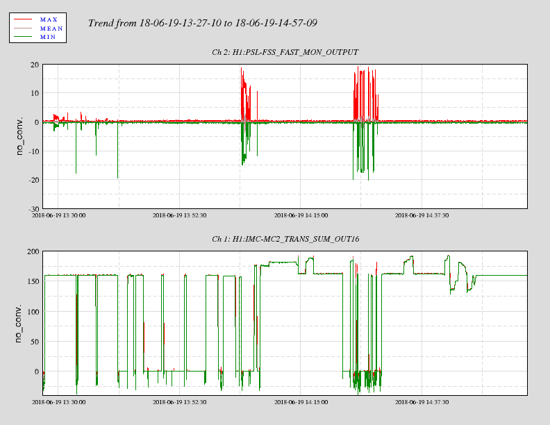
DAQ was restarted soon after the ISI model restarts at the end of the maintenance period.