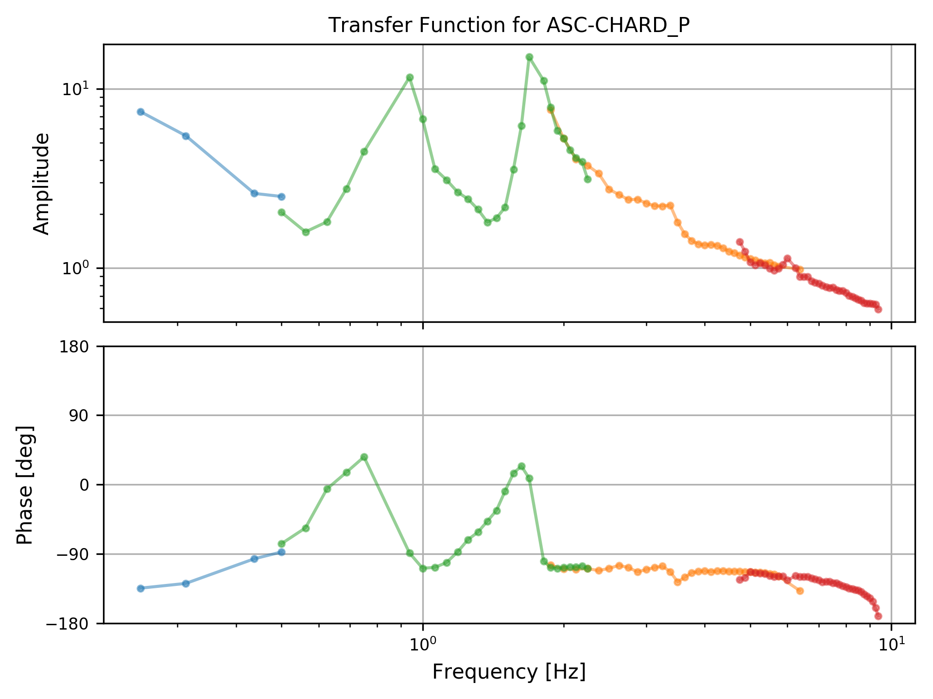
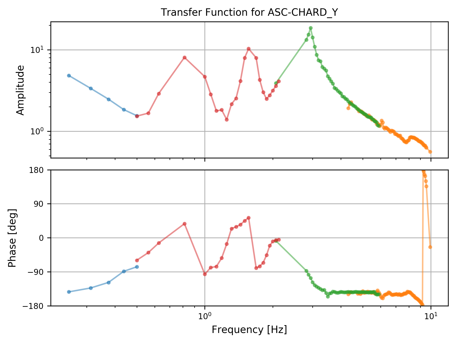
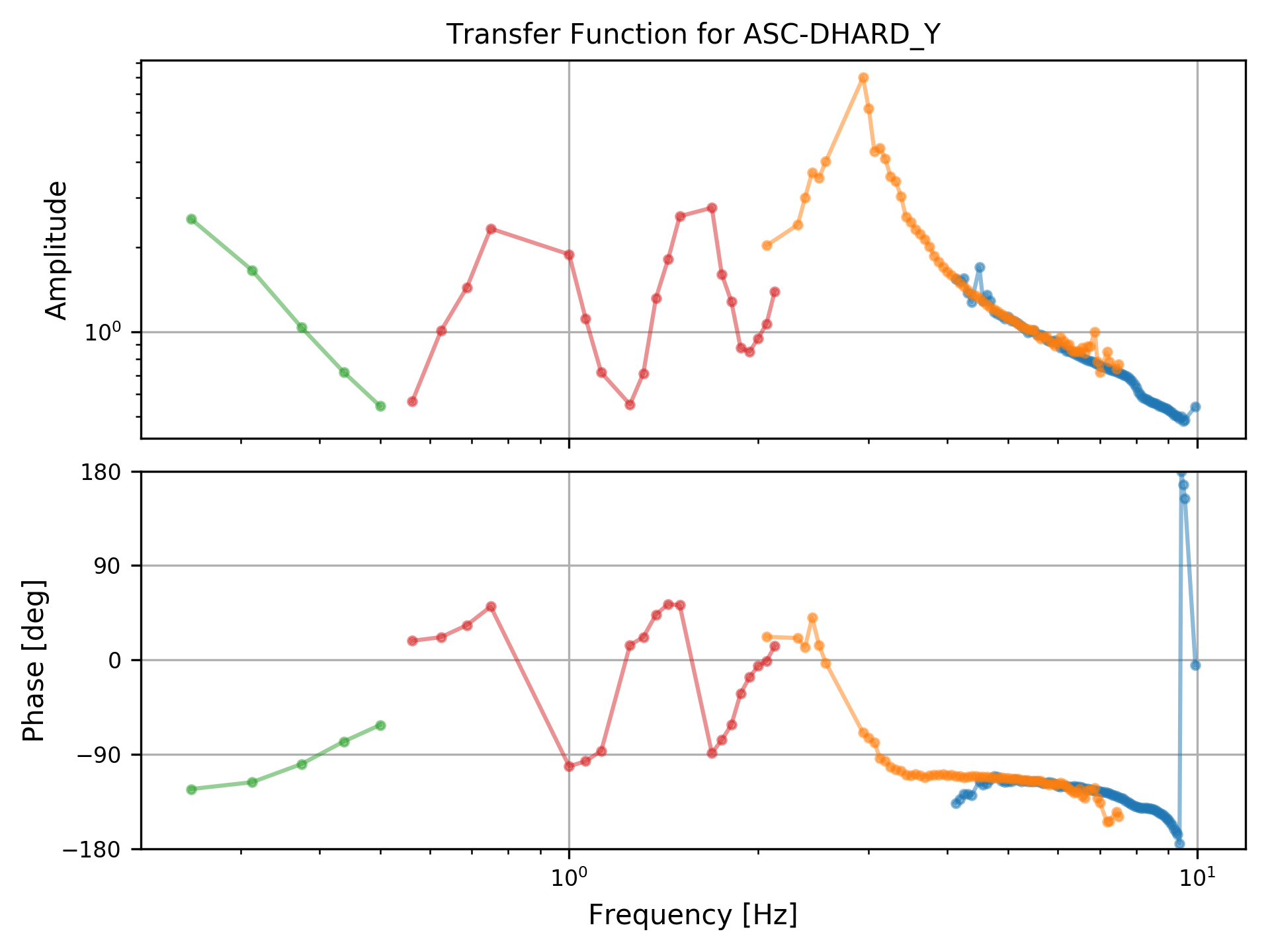
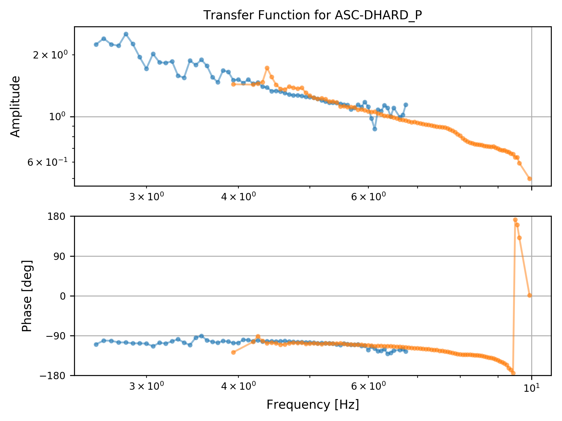
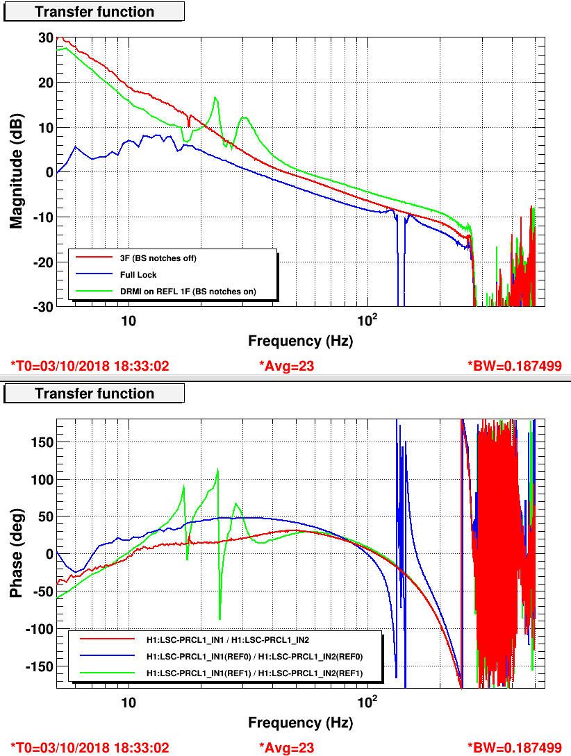
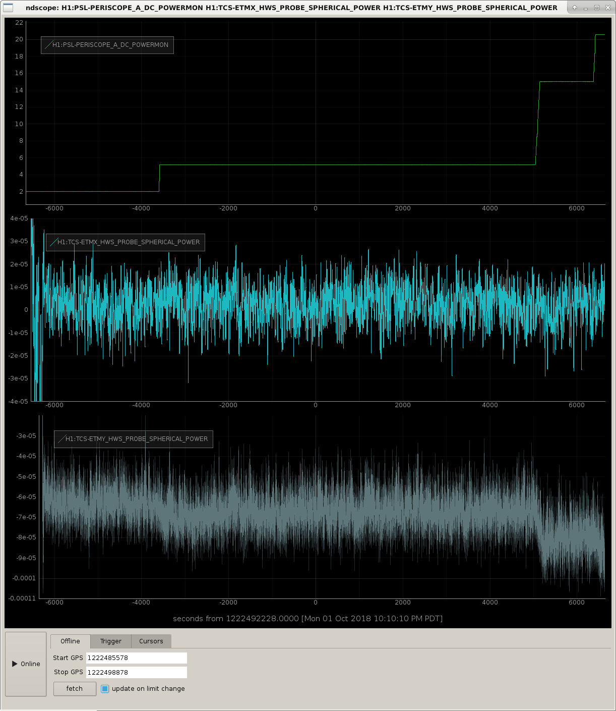
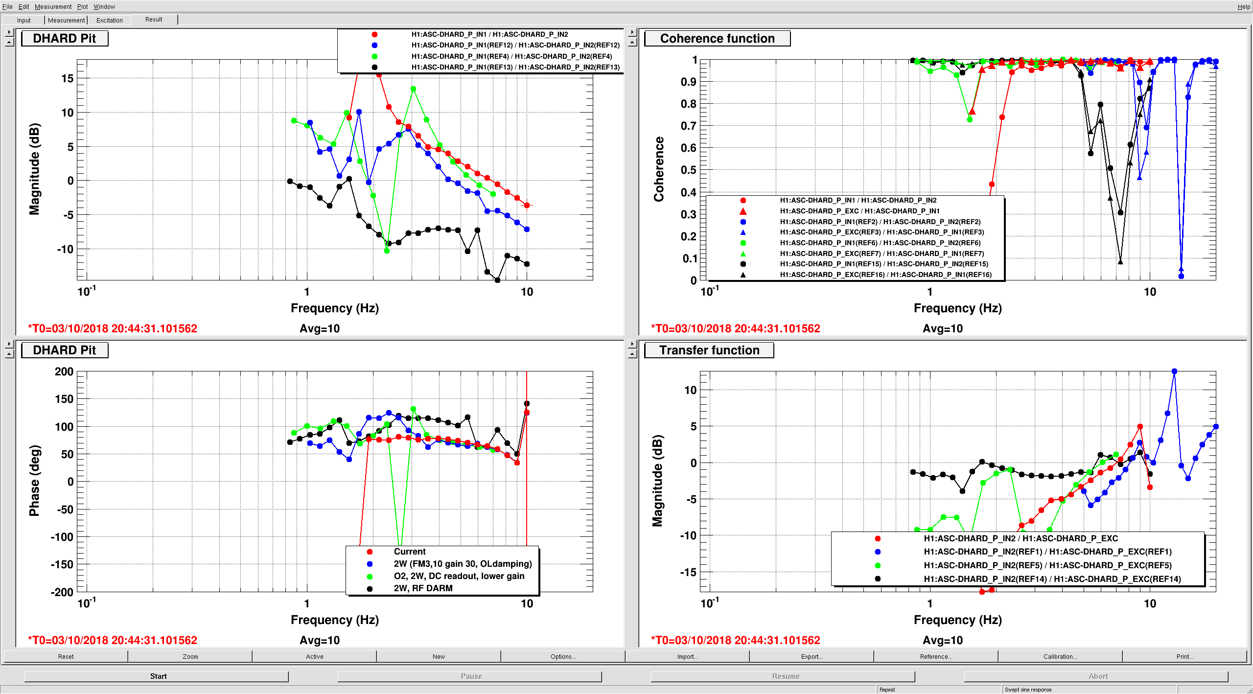
Late entry: yesterday we measured the hard loops with the sweep sine templates. Results attached.
The strange thing is that CHARD has a much lower phase margin than expected, and lower than DHARD. Our expectation would be that the C and D loops should be similar. Also, it looks like CHARD has an additional slope at low frequency.
The templates XML files are in /ligo/svncommon/IscSVN/iscmodeling/trunk/ALIGOH1/ASC_loops/Measurements/DHARD and /ligo/svncommon/IscSVN/iscmodeling/trunk/ALIGOH1/ASC_loops/Measurements/CHARD: CHARD_P_OLG_SS_2W.xml, CHARD_Y_OLG_SS_2W.xml, DHARD_Y_OLG_SS_2W.xml, DHARD_P_OLG_SS_2W.xml
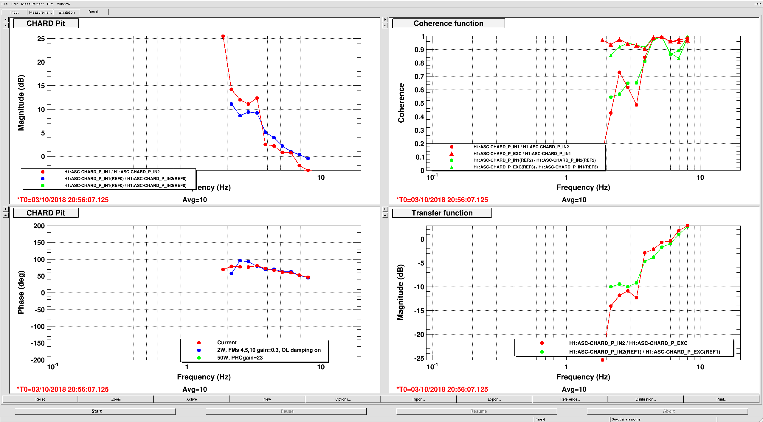


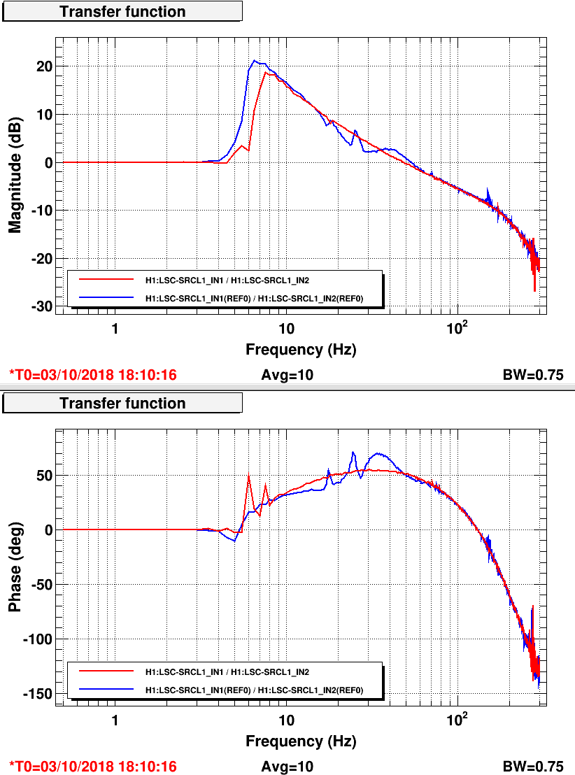
I also measured the HARD loops today, but using broadband noise.
I'm roughly comparing them to a pre-O2 measurement from June 2016 in alog 27832. In that measurement, as one might expect, the CHARD and DHARD Yaw OLGs are roughly similar.
Right now, they are definitely not. Note that the DHARD_P measurement doesn't go to as low of a frequency.
There is no real difference in the ASC control filters between CHARD and DHARD Yaw. CHARD Y has a low pass at 200Hz, but that is a very teeny amount of phase difference down at 6Hz. Hang has looked at the PDs, and there are no hidden lowpasses that he was able to find, that would explain this.