With the noise and problems we have been having with ALS X I attempted to Clean the fiber ends at all junctions between the LVEA and the End station. I used a FiberScope to look at the end before and after cleaning. The attached pdf shows one of the worse. This was the fiber that runs from EX patch panel to the Table. This is the patch panel end. All fibers showed visual improvement after cleaning.
I did not take apart the patch panel main runs. This would be the next step if we find this helps.

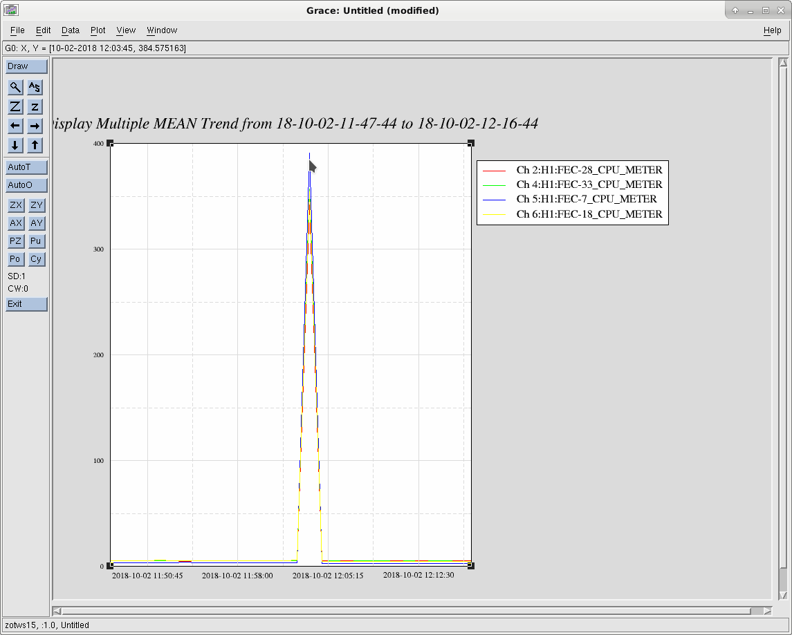
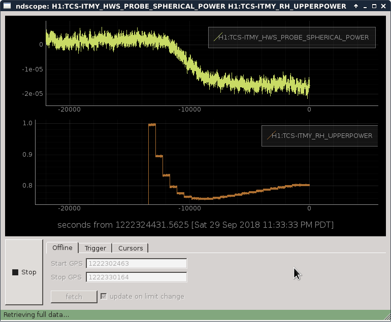
X end got better, now it's similar to Y. See the first plot (top) showing the past 18 hours or so, zero-power period corresponds to the maintenance. You need to look at peak to peak, ignoring the spikes.
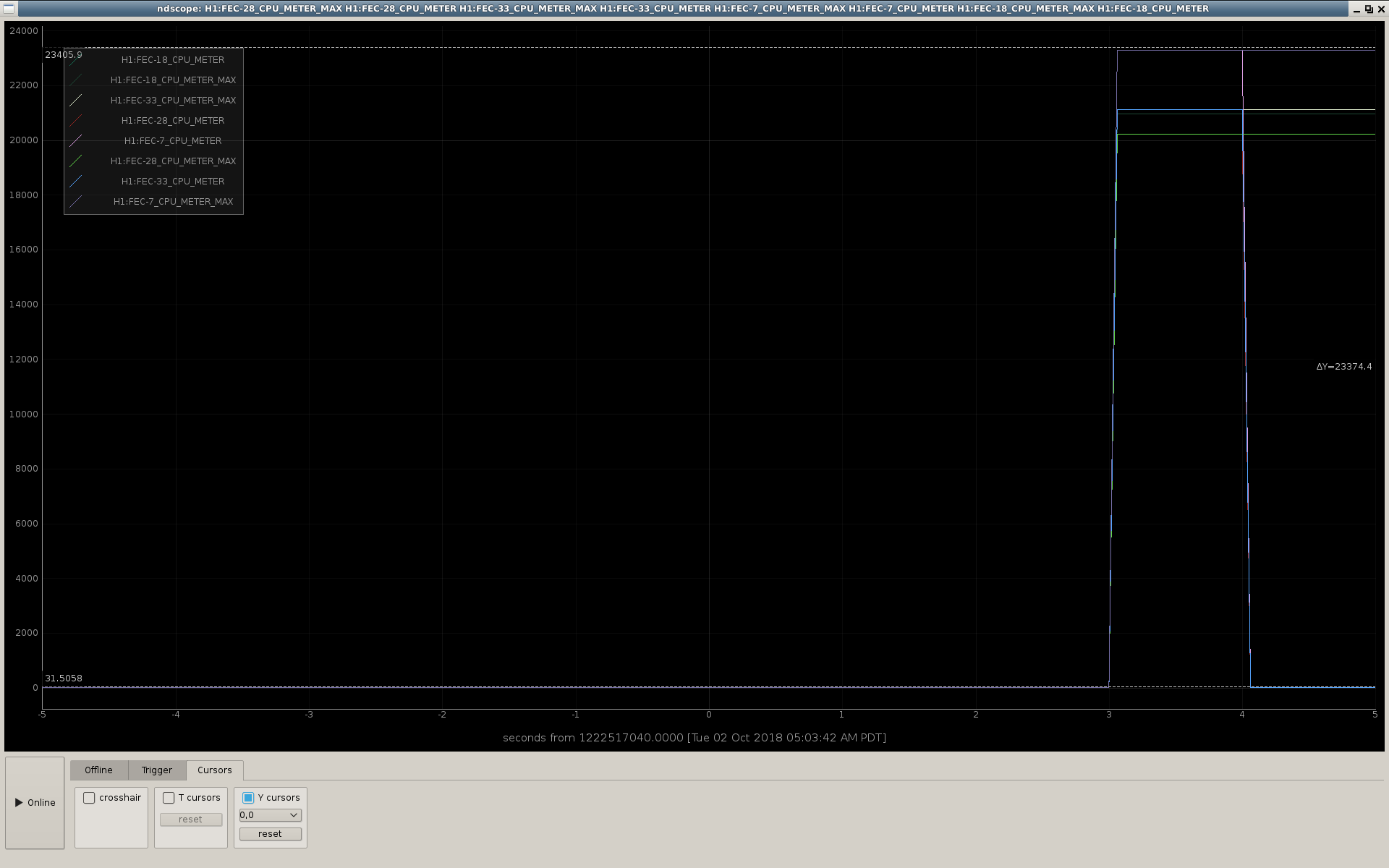
Don't worry about spikes as far as fiber is concerned, that's the result of failed locking attempts after the maintenance (IMC loses lock, FSS is kicked). See 2nd attachment.