jeffrey.kissel@LIGO.ORG - posted 08:38, Tuesday 02 October 2018 - last comment - 10:07, Tuesday 02 October 2018(44281)
ALS End Station WFS -- Unmonitoring Guardian Controlled Channels, Letting other DIFFs Perish
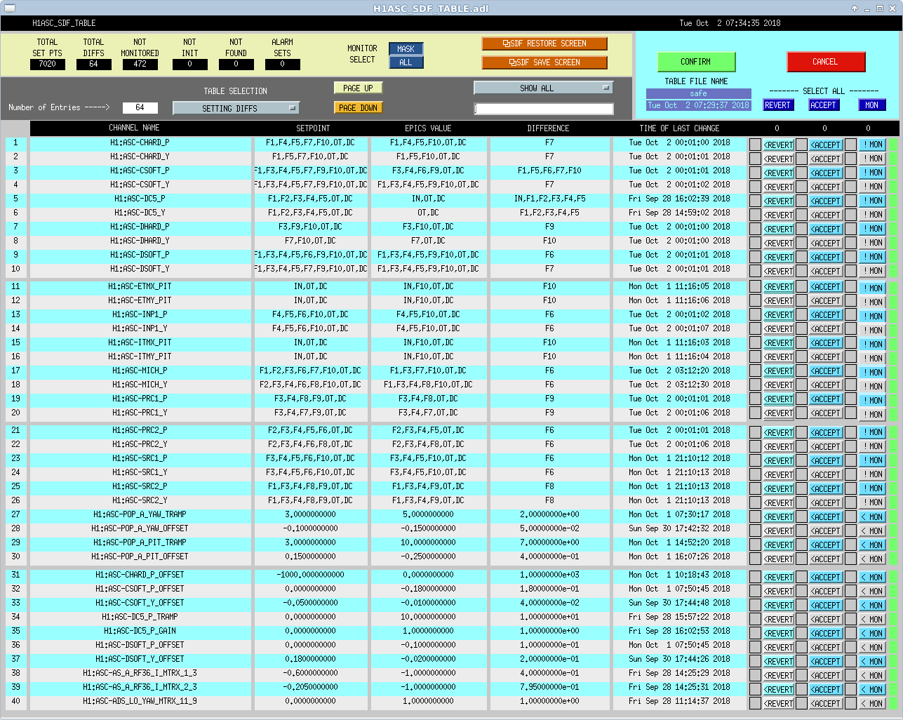
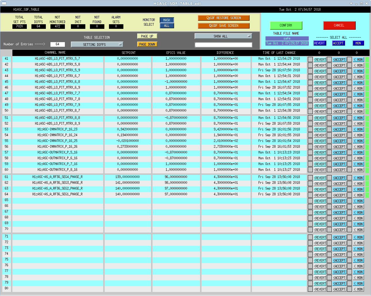
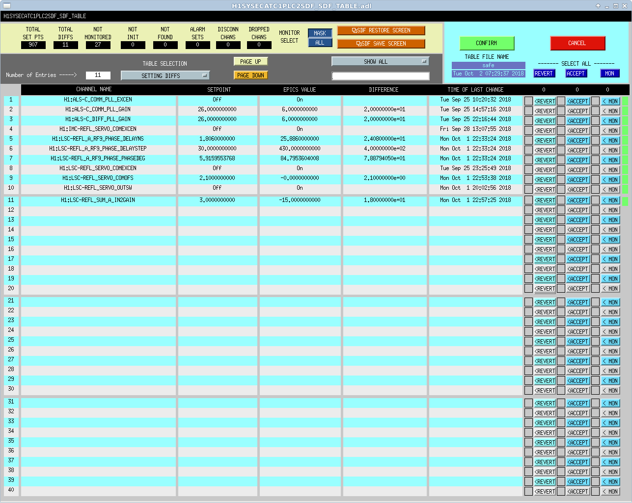
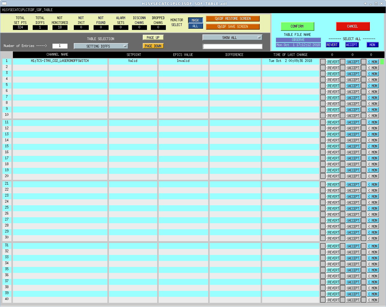
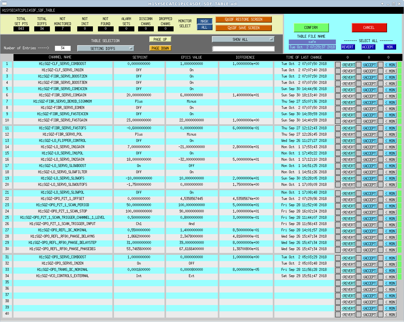
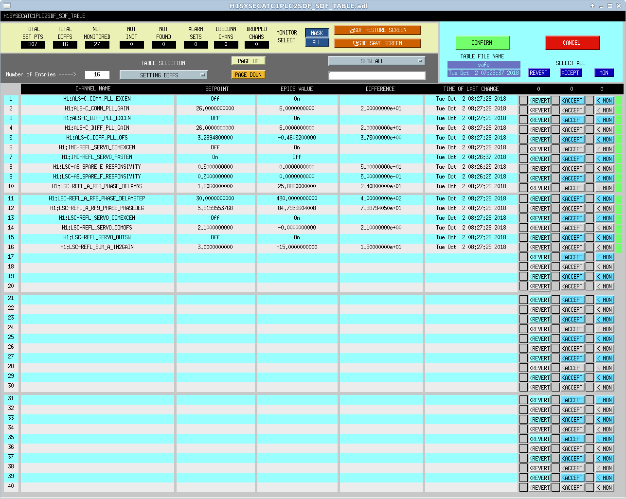
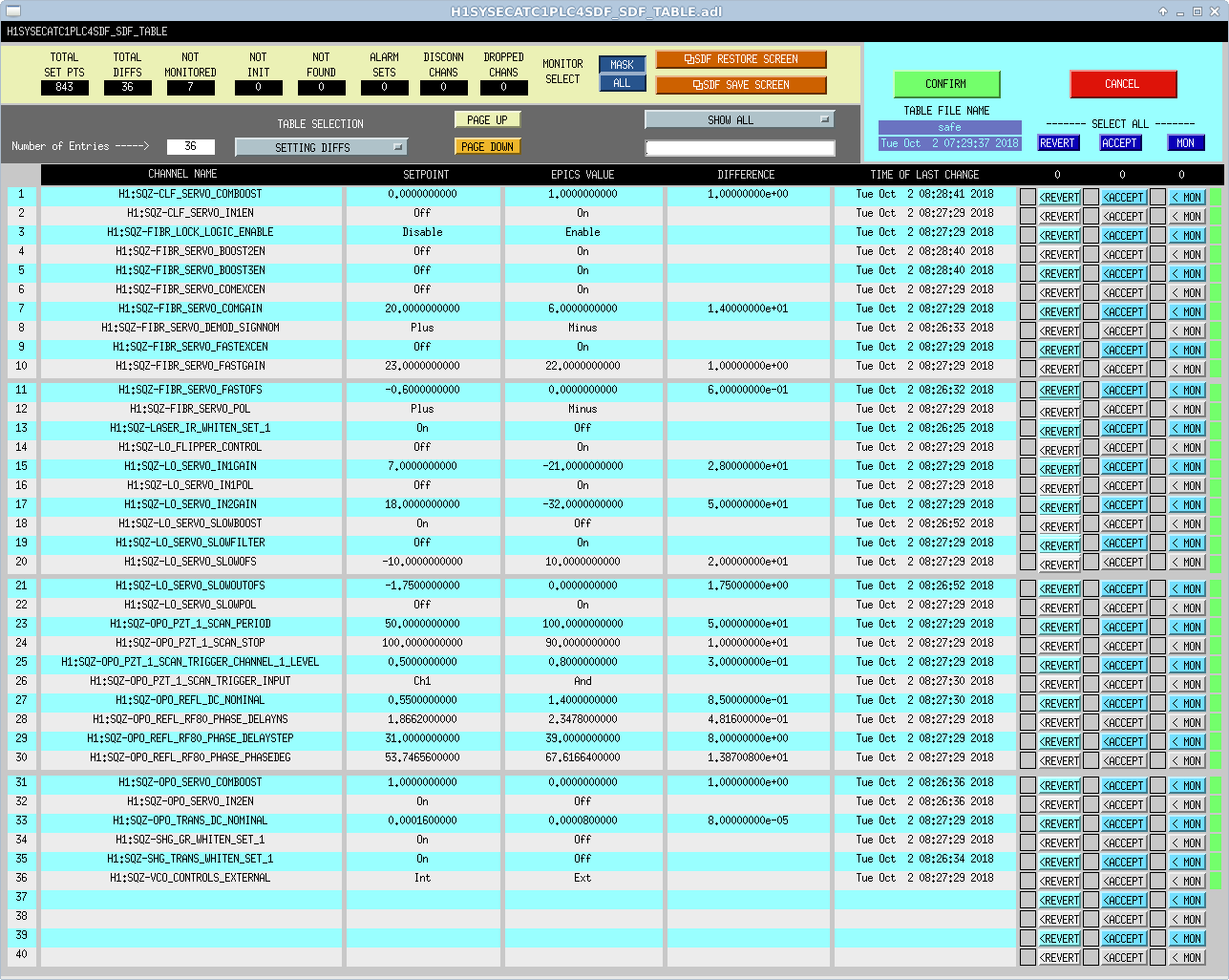
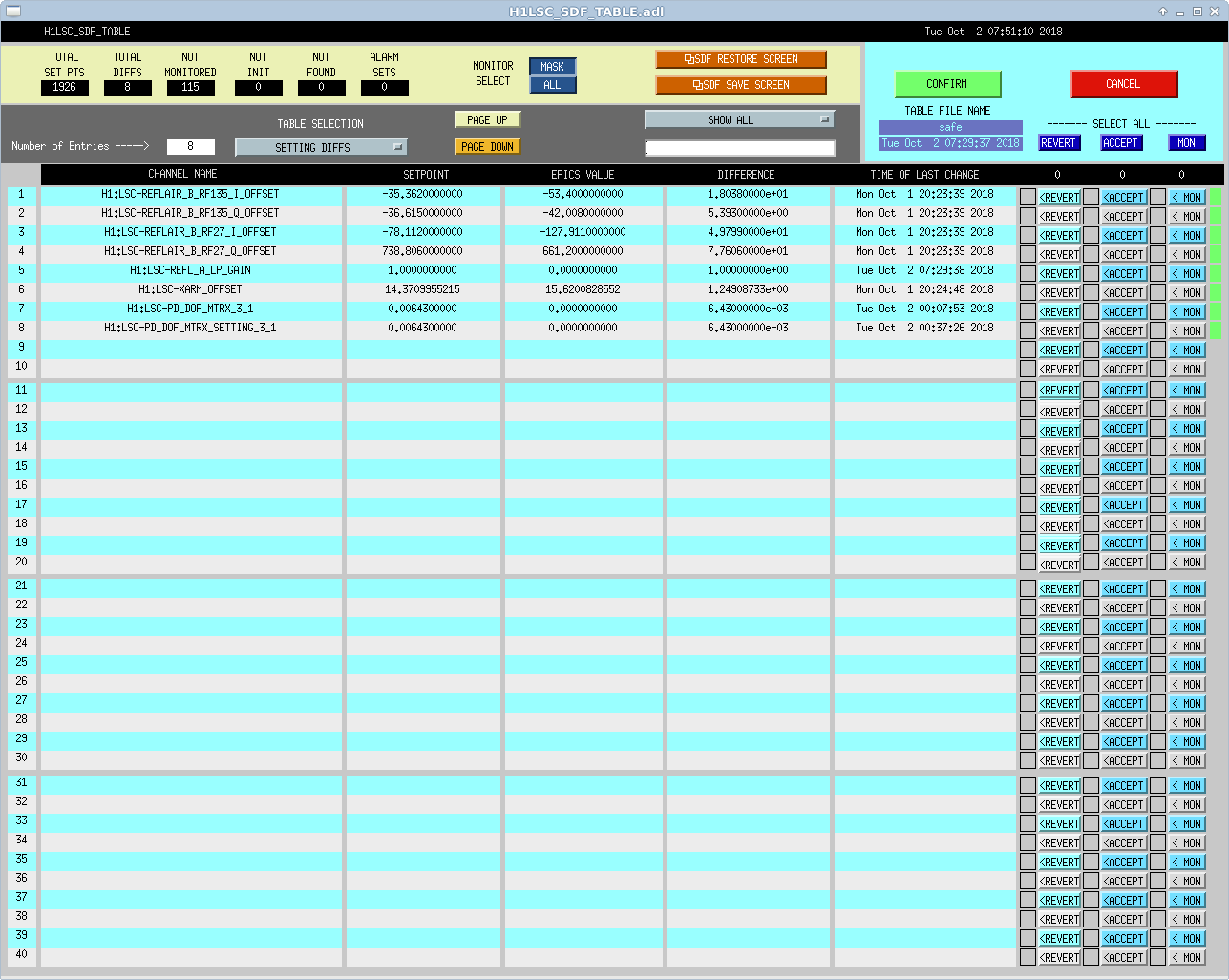
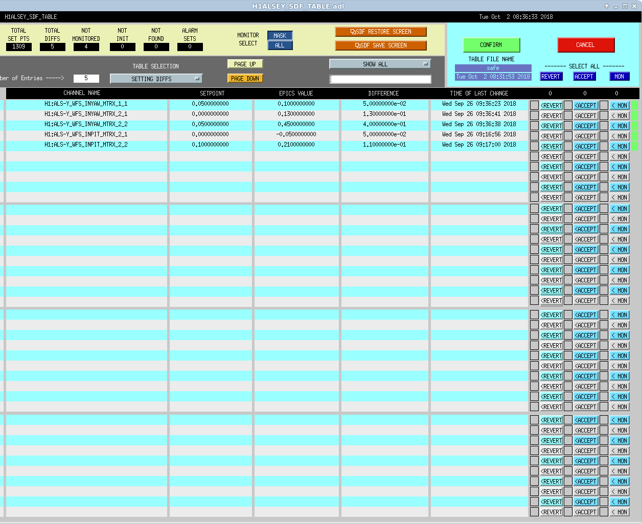
J. Kissel

Not clear if the end stations need to be rebooted this morning after the corner station front-ends seems to have crashed, but I'm reconciling the ALS EX and ALS EY front-end models with their settings definition files.

It is dreadfully obvious from the time stamp that a few filters in ALS WFS control (DOFs 1 and 2) are turned on and off by guardian during the lock acquisition sequence, namely FM9, a -14 dB gain filter. As such, I'm unmonitoring FM9 in the ALS-[X/Y]_WFS_DOF_[1/2]_[P/Y] filter banks. Note that these are filter banks, so I can individual monitor / unmonitor this filter module only, so I have. I've also consistently unmonitored the inputs to these filter banks, which are also guardian controlled, and weren't consistently unmonitored in any of the 6 filter banks.

There remains several diffs that are either
- related to the fact that we're currently ignoring ALS WFS on the X arm because they're broken LHO aLOG 44206, which appears to be coded into the guardian, or
- because (surprisingly) some of the elements of the ALS Y WFS sensing matrices have changed.

I attach the remaining diffs that I'm leaving present.
Images attached to this report

Comments related to this report
Both X and Y end ALS WFS sensing matrices were changed on September 26th, as reported in 44178.
The new values should be accepted.