Summary
I think Hang's conclusions about the sign flip in the sensing matrix for CSOFT are wrong. Here's why, in brief:
- the new sensing matrix (with hang's changed sign) has degenerate rows for DSOFT_P and CSOFT_P, so with that configuration we are sensing only one of the two degrees of freedom
- I tried to step CSOFT_P and DSOFT_P (with a step of 0.3 slider units, using Hang's script move_ARM.py) and found that both CSOFT_P and DSOFT_P signals are sensitive ONLY to DSOFT (see plot below)
- I measured a sensing matrix at DC, and found that the signs do not match what reported by Hang's measurement.
- Inverting my DC measurement of the sensing matrix and using it, I get a nice decoupling of CSOFT_P and DSOFT_P.
Details
Step responses
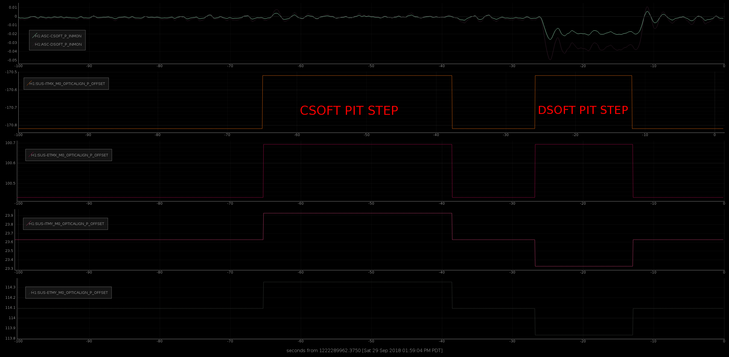
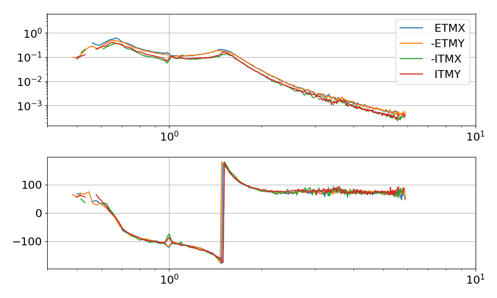
Below the response to a step (with all soft loops open) in both CSOFT and DSOFT, by 0.3 slider units, using Hang's move_ARM.py script. The plot right below shows the response of both DSOFT and CSOFT error signals with the sensing matrix that has Hang's change of sign. Clearly both signals respond only to DSOFT, and are orthogonal to CSOFT. So even though in this configuration we are closing both CSOFT_P and DSOFT_P, we are controlling only DSOFT_P.
Sensing matrix at DC
I measured again the CSOFT / DSOFT / TMSX / TMSY sensing matrices for the four TRANS QPDs, using the same script used in the past. The results for pitch and yaw are reported below, in units of QPD signals over test mass and TMS slider values:
| |
CSOFT_PIT |
DSOFT_PIT |
TMS X PIT |
TMS Y PIT |
| H1:ASC-X_TR_A_PIT_INMON |
0.027080 |
0.025287 |
0.081631 |
-0.000531 |
| H1:ASC-X_TR_B_PIT_INMON |
-0.030390 |
-0.032043 |
0.162007 |
-0.001058 |
| H1:ASC-Y_TR_A_PIT_INMON |
-0.001537 |
-0.003221 |
0.000275 |
0.089293 |
| H1:ASC-Y_TR_B_PIT_INMON |
-0.187802 |
0.186769 |
-0.000672 |
0.182058 |
| |
CSOFT_YAW |
DSOFT_YAW |
TMS X YAW |
TMS Y YAW |
| H1:ASC-X_TR_A_YAW_INMON |
-0.012131 |
-0.011012 |
0.110482 |
0.000160 |
| H1:ASC-X_TR_B_YAW_INMON |
0.138589 |
0.137854 |
0.240005 |
-0.002157 |
| H1:ASC-Y_TR_A_YAW_INMON |
0.003813 |
-0.010138 |
-0.001525 |
0.097219 |
| H1:ASC-Y_TR_B_YAW_INMON |
-0.115291 |
0.122388 |
0.001860 |
0.151168 |
Comparing the sensing matrix elements for CSOFT in my measurment and Hang's measurements, there's a sign flip for all Y QPDs. I am not sure what the origin of this difference is. However, I inverted the pitch and yaw matrices, to obtain the following:
| |
H1:ASC-X_TR_A_PIT_INMON |
H1:ASC-X_TR_B_PIT_INMON |
H1:ASC-Y_TR_A_PIT_INMON |
H1:ASC-Y_TR_B_PIT_INMON |
| CSOFT_PIT |
12.185237 |
-6.159686 |
5.330350 |
-2.614611 |
| DSOFT_PIT |
11.668271 |
-5.858967 |
-5.454441 |
2.675180 |
| TMS X PIT |
4.597597 |
3.856154 |
-0.006480 |
0.039001 |
| TMS Y PIT |
0.616454 |
-0.329222 |
11.094065 |
0.051387 |
| |
H1:ASC-X_TR_A_YAW_INMON |
H1:ASC-X_TR_B_YAW_INMON |
H1:ASC-Y_TR_A_YAW_INMON |
H1:ASC-Y_TR_B_YAW_INMON |
| CSOFT_YAW |
-6.957181 |
3.270353 |
6.010876 |
-3.811676 |
| DSOFT_YAW |
-6.338919 |
2.849835 |
-5.982599 |
3.894886 |
| TMS X YAW |
7.655904 |
0.642867 |
0.050068 |
-0.031134 |
| TMS Y YAW |
-0.268093 |
0.179000 |
9.427309 |
0.555133 |
Based on those measurements, and rescaling the elements so to match the size and sign of the current, error signals, I computed a new ASC input matrix for soft pitch and yaw and implemented it. It's very close to the old one, before Hang's sign flip.
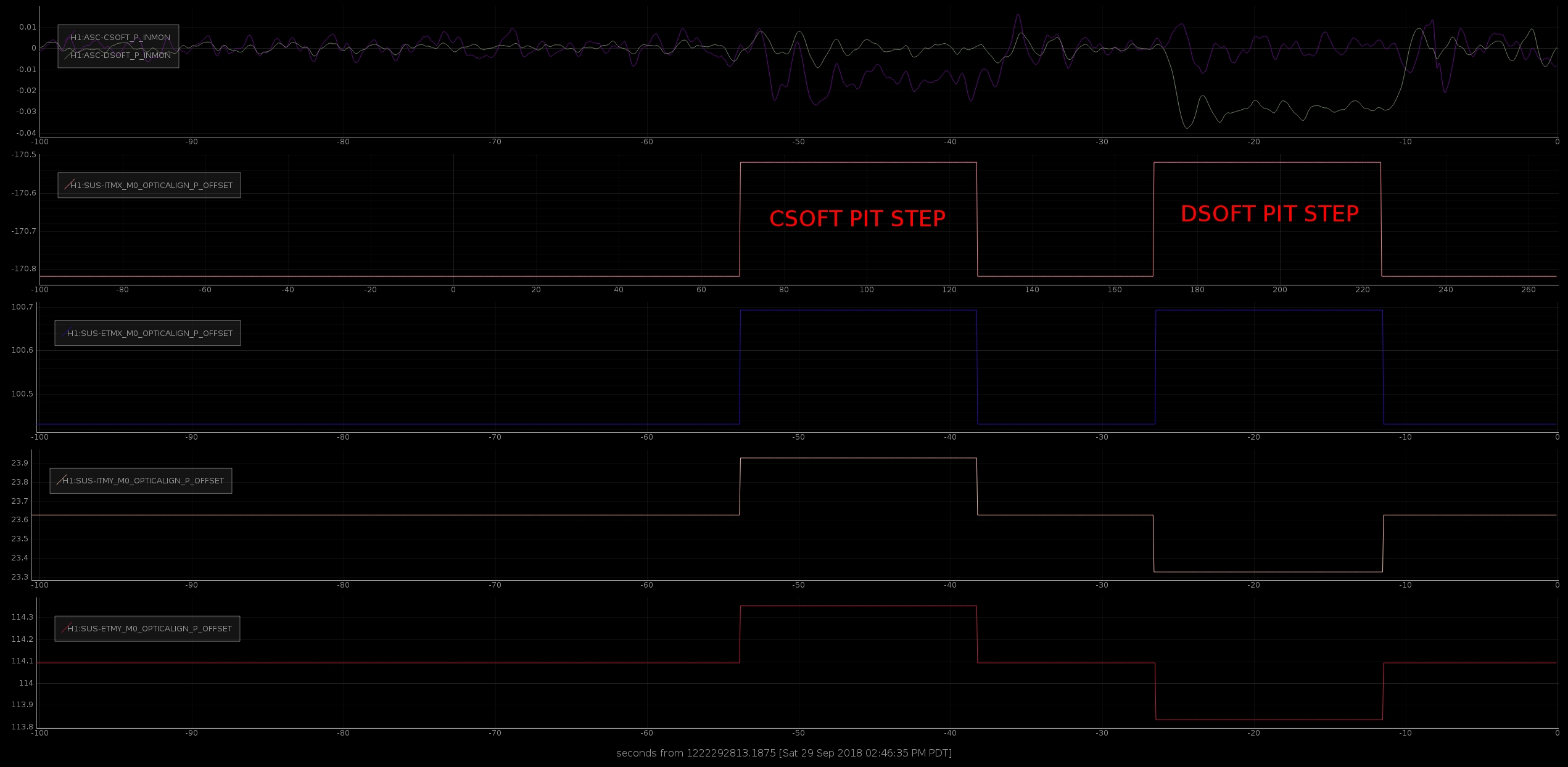
New step response
With the new input matrix, the CSOFT and DSOFT error signals behave as expected:
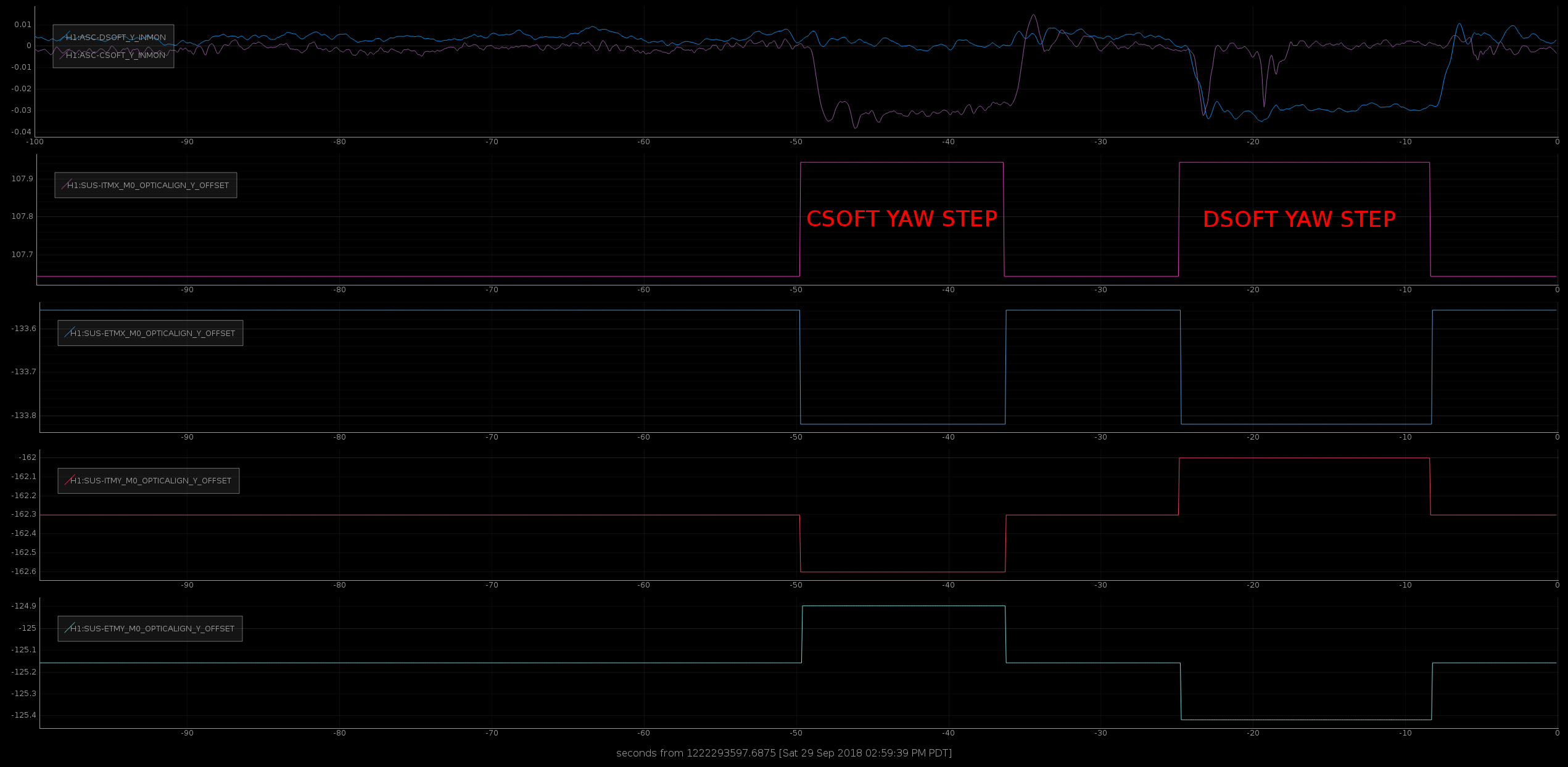
To cross check, I also stepped CSOFT_Y and DSOFT_Y, and foud the error signal properly decoupled:
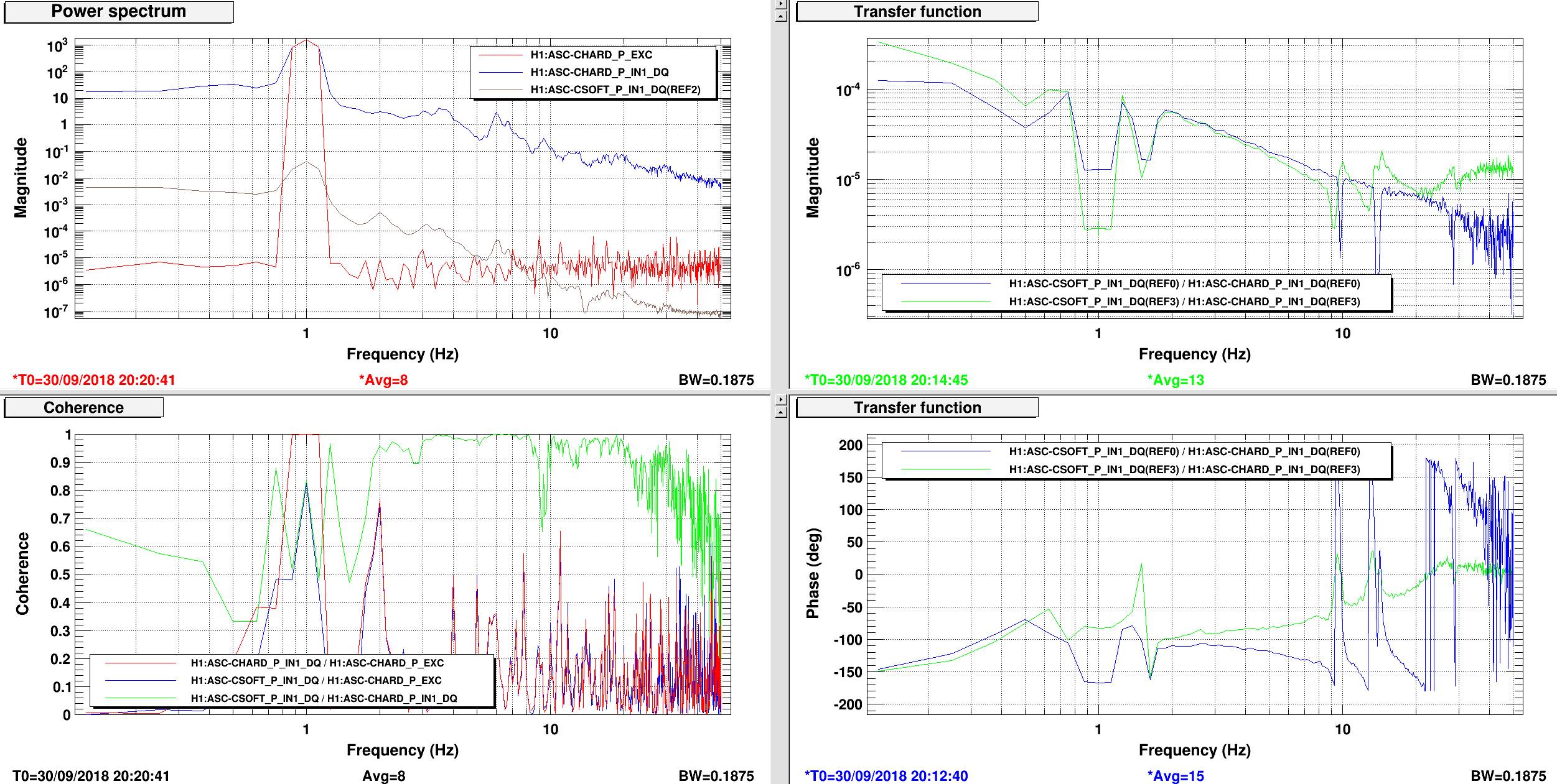
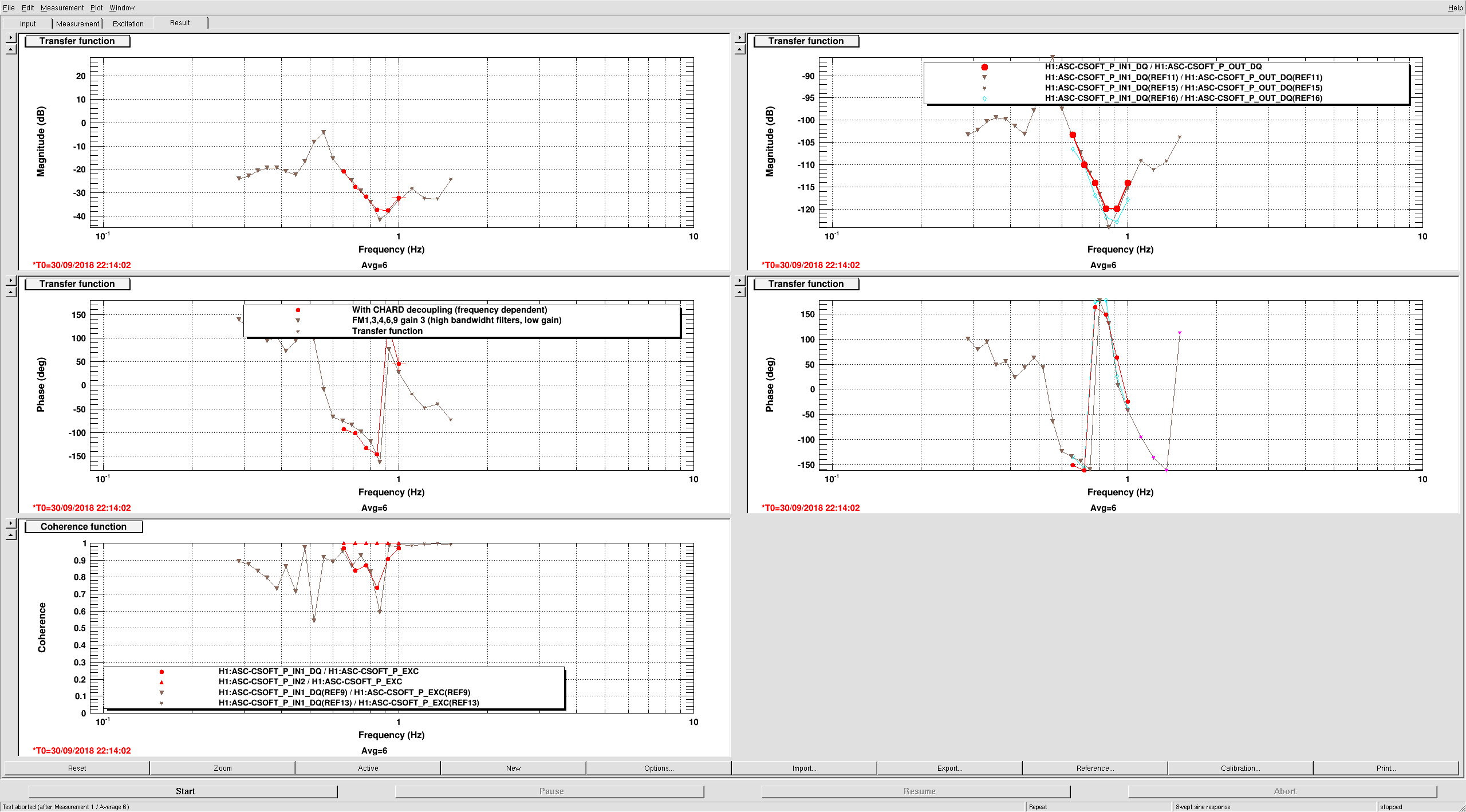
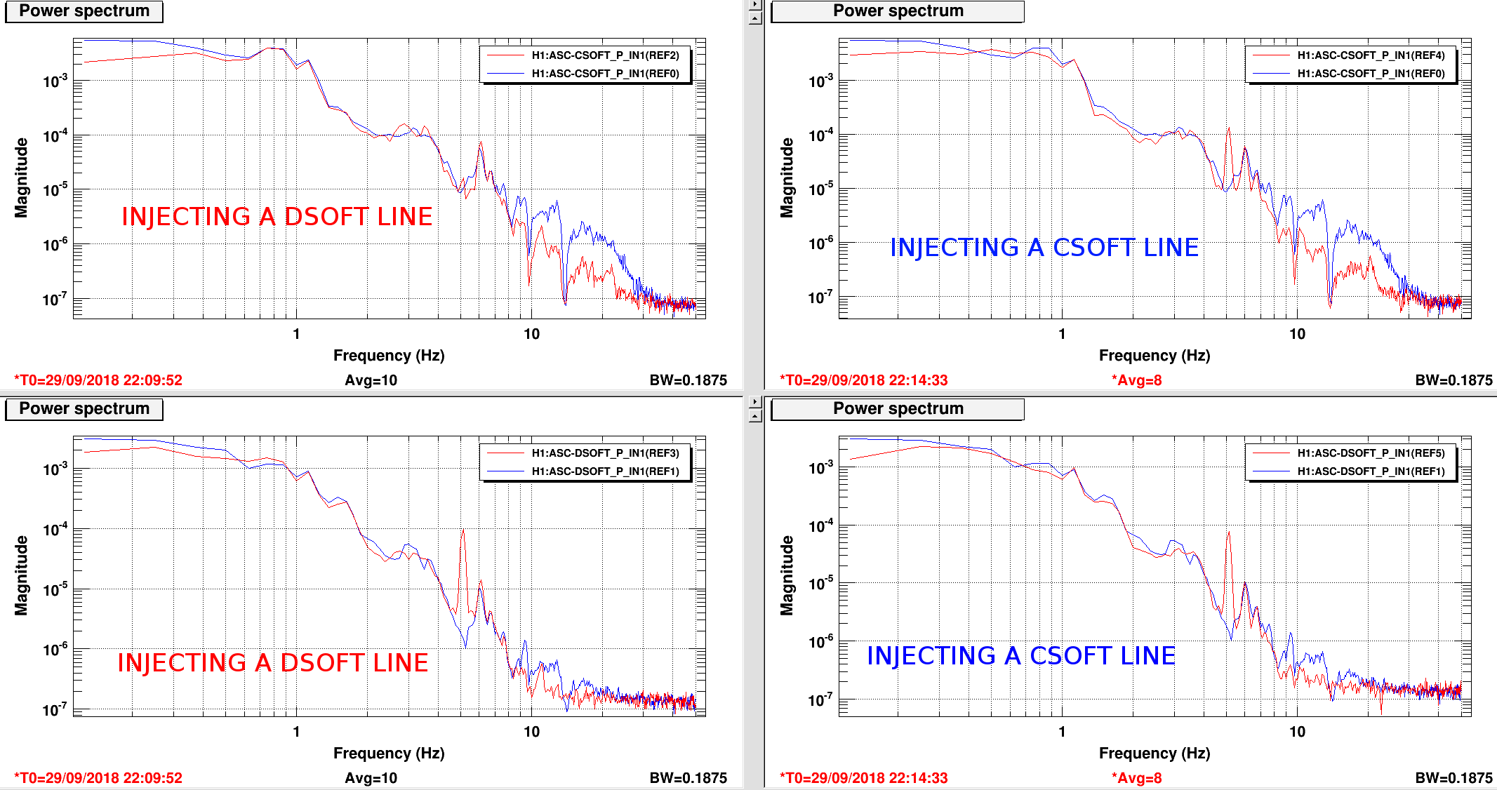
A also did a quick measurement, with both CSOFT and DSOFT PIT loops closed, by injecting a line at 5.1 Hz. When injecting a DSOFT line, only the DSOFT signal sees it. Instead, when injecting a CSOFT line, there is some cross-coupling to DSOFT: the DSOFT signal also sees a line at 5.1 Hz, just a bit smaller than what is seen in CSOFT. It's not clear to me why this is the case. See fourth attachment.


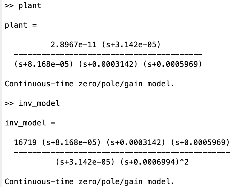
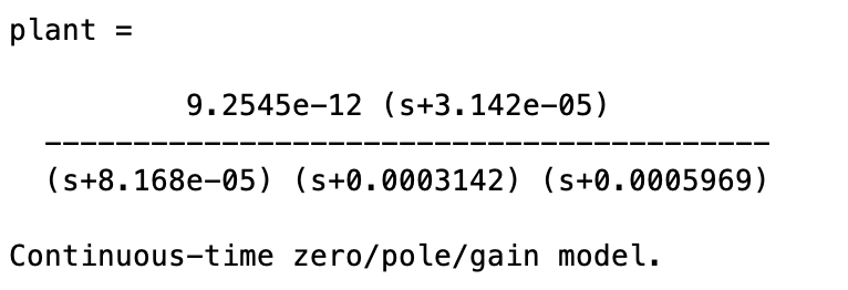
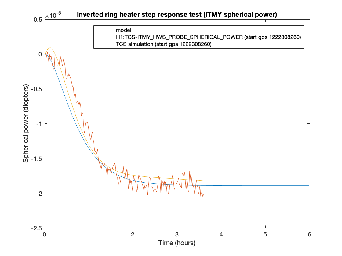


Model attached.