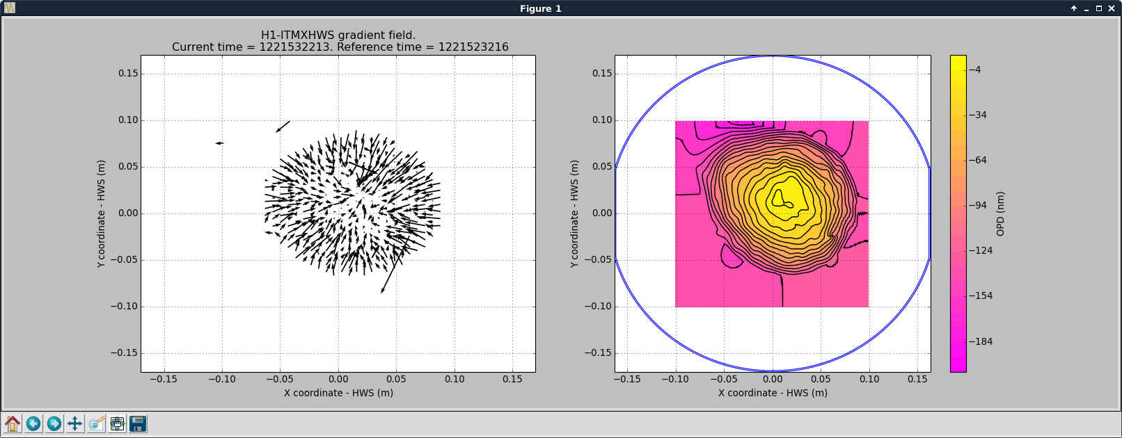
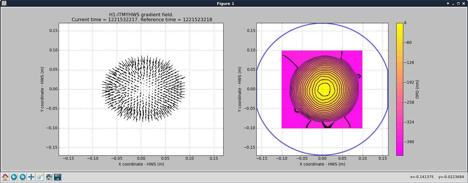
Carlos and Jonathan. We did some updates to the EPICS CA Gateway cdsegw0 under WP 7200. The goal was to replace it with a newer machine running a current operating system. The new system would be running Debian 9, EPICS 3.15.3, the EPICS CA Gateway, and move the config into puppet control. The current system ran 6 EPICS gateway processes, with 4 of the processes sharing the same server IP/port. The new system had problems running in the same configuration. We could read the vacuum network from all of the interfaces, but could not read the FE/slow controls/and aux gateways. Further investigations are required to state exactly why. At this time we are not sure if it was a configuration setting that did not get transferred over, or just a difference in EPICS base versions as we moved from 3.14.x to 3.15.3. After discussion with Dave we questioned the need for so many gateway processes. In previous revisions of the system, the gateways were needed to rate limit access to VxWorks boxes. These boxes have all been replaced, and the gateways are really are only needed to provide a read-only view of the vacuum channels. The plan was adapted to run the gateway server with only the vacuum network gateway processes, turning off the server -> FE, server -> slow controls, server -> aux gateways. This was done this morning, using the old system with a smaller number of EPICS CA gateway processes running. If this works out we will likely open a new work permit and replace the old gateway box with the new box, but without attempting to multiplex 4 gateways onto one interface (which is the problem we ran into).
Jonathan, Dave:
Following this morning's removal of three epics gateways on the internal gateway machine (the three gateways with SIP=10.20.0.5 and clients on h1fe, h1aux and h1slow) my cell phone texter crashed and would not reconnect to any subnet other than h0ve. We found that the CA env vars were not set and the code was dependent upon a gateway on the cds vlan (10.20.0/24). Defining the env vars in the startup script fixed this issue.
D. Barker, S. Dwyer, J. Kissel, E. Merilh, C. Vorvick While resuming alignment of the IMC this morning, we were confused and surprised to see the IMC mirrors and PZTs being driven around without our doing. The problem was that the MC WFS servos had triggered at around 19:10 UTC after we opened the light pipe and began shooting light down to MC2 TRANS, the SUM of which serves as the trigger PD**. Because the P and Y path from these servos' output -- all the way to each MC1, MC2, and MC3 mirrors -- is, by default, always on, this non-sense drive was driving around the suspensions and PZTs. Because we don't want anything but humans driving the suspensions for the foreseeable future (until chamber doors start to go back on) I've taken the following disabling measures: - Turned of the input to the MC1, MC2, and MC3 top mass (M1 LOCK) P and Y filter banks, - Accepted this change in each suspensions safe.snap SDF file. - Turned up the trigger on/off thresholds for the MC WFS (H1:IMC-IMC_TRIGGER_THRESH_ON / H1:IMC-IMC_TRIGGER_THRESH_OFF) from 40 / 20 to 5000 / 500. - Accepted into the safe.snap file of h1ascimc - Un-managed MC2 from the IMC_LOCK guardian. - Moved the IMC_LOCK guardian to PAUSED so that it's no longer running (just a precaution, really, the MC WFS are all triggered via front-end logic). - Cleared the history on all MC WFS servos. - Restored all alignment offsets (PSL PZTs, MC1, MC2, and MC3) to there values reported at the close of business yesterday (see LHO aLOG 39299) An as-of-yet unsolved mystery is why we're getting so much more sum counts on the MC2 trans (during yesterday's flashing we hit 2 or 3 [ct] max, now we've hit 25 - 30 [ct]). **The trigger is not just MC TRANS SUM, but H1:IMC-MC2_TRANS_SUM_OUT / H1:IMC-PWR_IN_NORM_MON. The demoninator, H1:IMC-PWR_IN_NORM_MON, is set to 0.1. So with a sum of 25-30 [ct], the triggered value becomes 250-300, and surpasses the (former) threshold of 40 [ct].
Sheila has opened FRS Ticket 9387 so as to better reflect the trigger logic on the IMC / IMC WFS MEDM screens.
For the record: the above unsolved mystery of strangely high MC2 TRANS SUM was a result of an LED Work Lamp being left on pointed on the +Y (global IFO coordinates) of HAM3, which Jim had turned on to rotate and align the new PR2 scrapper baffle (aLOG pending). Once we arrived at HAM3 for our afternoon session, we turned off the lamp, and the SUM returned to there expected value of 2-3 counts (supposedly [uW]) with the parachute cover OFF (while looking in chamber at MC2's iris) and 0.5-0.9 [uW] when the parachute cover is on.
Dan, Dave:
Prior to this morning's DAQ restart I reconfigured h1nds1 (default NDS) to serve the archived raw minute trend data which Dan had recovered over the weekend onto the new SATABOY-RAID (a ZFS files system with compression enabled). I tested this to verify minute trend data is now available from the aLIGO DAQ epoch which is 12:25 PST Wed 16 Jan 2013. Attached plot shows a pem seismic channel for the whole year of 2013.
The raw minute trends are stored on a compressed ZFS file system, built on a re-purposed SATABOY RAID. Compression is done in software on the Oaracle/Sun Microsystems 4270 computer. Getting 500 days of minute trend data took h1nds1 only 5 seconds to retrieve and plot.
The compressed ZFS file system is 10.8TB in size. The current four years of raw minute trend data is consuming only 2.6TB of this (24%). We should be good for raw minute trend storage for many years to come.
Dan is now restoring all the archive min trend data onto h1ldasgw1's SATABOY. ETA is Friday.
WP7206 Brian, Jim, Dave:
ISI-HAM[2-6] models were modified, compiled, installed and restarted. The DAQ was then restarted at 10:05 PST.
This morning I performed the weekly PSL FAMIS tasks.
HPO Pump Diode Current Adjust (FAMIS 8447)
With the ISS OFF, I adjusted the HPO pump diode operating currents; this week required a larger increase than usual from all 4 HPO DBs, this is summarized in the below table. As usual, I attach a screenshot of the PSL Beckhoff main screen for future reference.
Operating Current (A) | ||
Old | New | |
DB1 | 51.3 | 51.6 |
DB2 | 53.7 | 54.0 |
DB3 | 53.7 | 54.0 |
DB4 | 53.7 | 54.0 |
I did not adjust the operating temperatures of the DBs. The HPO is now outputting 155.0 W and the ISS is back ON. This completes FAMIS 8447.
PSL Power Watchdog Reset (FAMIS 3675)
I reset both PSL power watchdogs at 17:55 UTC (9:55 PST). This completes FAMIS 3675.
Apparent LASER trip (10/31) and corresponding aLog. Environmental data seems to have quieted. An incursion by Peter, yesterday, is also apparent. All other data appears to be normal.
I'll detail the rebalancing after I review the previous payload to document changes--Exec Summ: removed many kgs.
My tabulation of the payload results in a reduction of balance masses by 11.75Kgs.
Just wanted to outline my process for balancing the ISI:
1) With ISI still locked, reset RX RY target to LOCATIONMON value (cartesian LIGO global), set Z target to locked position plus 20um.
2) Unlocked ISI and balanced to get RESIDUALMON pretty close to zero so that locking was easy.
3) Relocked and unlocked a few times looking for repeatability.
4) Reset the RX RY and Z targets to new locked position. It is not unexpected for the locked position to change like this after lots of work on the table. These changed -46urad, +11urad, +0.7um for RX RY and Z.
5) unlocked and fine tuned the balance.
6) Relocked and consolidated and secured all masses. Unlock to lock change: RX -7.4urad, RY +0.6urad, Z -19um.
7) Updated SDF for RX RY and Z Target, e.g., H1:ISI-HAM4_CPS_RX_TARGET w/ Z set less the 20um for in air buoyancy effect.
FWIW--Locking the ISI at this balance condition was easy, unlike unlocking it when it was 11kg heavy. Lightest weight balance item is ~50grams.
S Cooper, S Dwyer, J Kissel
Sam has been looking into what trips in what order durring large earthquakes, and one thing he has run into is that we have different RMS thresholds for tripping different suspensions, meaning that for some optics R0 will trip while M0 might not for a particular EQ. I have gone through the QUADS and set the RMS MAX to be the larger setting where settings differed between optics. SDF screenshot showing changes is attached.
Kyle R., Rakesh K. Today we vented the ion pump, decoupled the KF flexline which had connected the 55 L/s ion pump to CP2's 1.5" pump port and then reconfigured the fittings and added a small turbo to the ion pump assembly. We will make the connection of the ion pump assembly to CP2's pump port valve tomorrow. For tonight, we pumped down the IP side of the 1.5" pump port isolation valve via the leak detector and will leave it connected, under vacuum and turned off. The leak detector is hose-clamped to a fixed post to prevent it from being moved, and thus, straining the connection to the pump port isolation valve.
Today:
Tomorrow:
- Cheryl JeffK, JeffB, PeterK
On The IM4 Cage Baffle Assembly D1002745 This aLOG is merely to provide data on the troublesome IM4 baffle assembly such that it might be improved in some vent in the future. As one may recall, in order to adjust the pitch alignment of the IMs / HAUX / HAM Auxiliary suspensions, one must remove their cage protection baffle. Recall that each of the IMs have their individualized cage protection baffle, Optic Former Baffle Name Drawing / Assembly IM1 SM1 D0902378 IM2 PMMT1 D0902380 IM3 PMMT2 D0902382 IM4 SM2 D1002745 where IM1's baffle has a large opening, IM2 and 3's are (from what I can tell) identical, and IM4 has much larger coverage, and has a special insert D1002722 in order to provide further protection for the suspension wires against stray IFO REFL beams during lock loss. It is this special insert that gives us the most trouble when taking the IM4 baffle assembly on and off, because it does not clear the suspension cage's front (HR-side) earthquake stop brackets (D1000539, D1000540, D1002360, D1002361) when they're secure. One needs to loosen bolts and back off these EQ stop brackets to remove this baffle. Attached are several pictures: (1) & (2) show the baffle assembly after removal from the IM4 cage (3) show the drawing numbers for each baffle part (4) shows the metal erosion at the baffle's contact points with the EQ stop brackets (5) shows IM4 after the baffle has been removed, highlighting the EQ stop brackets (6) & (7) show the particulate that erodes off of the baffle every time we remove & re-install it. The pains experienced during removal and re-install of this baffle assembly are not new. Kiwamu and I had trouble in the last vent when we were mechanically relieving the alignment sliders (see the bottom of LHO aLOG 12811) and during original install by Cheryl and Deepak (see 5633) LLO aLOG 3814 seem to imply that something was done chamber-side to L1 IM4 to make the baffles fit better.
TITLE: 11/07 Day Shift: 16:00-00:00 UTC (08:00-16:00 PST), all times posted in UTC
STATE of H1: Planned Engineering
INCOMING OPERATOR: None
SHIFT SUMMARY:
LOG:
17:45 Kissel to HAM2, Hugh to HAM2
18:00 Cheryl to HAM2, Hugh to HAM4
18:30 Jason, Betsy, Travis to Biergarten
19:00 Terry to sqz
13:00 Travis to Biergarten
21:45 Cheryl to HAM2, Peter to PSL
22:00 Terry to sqz
22:15 HFD on site for quarterly tour
22:45 Kyle to LVEA
22:45 Peter to LVEA
still in the LVEA as of 23:46UTC:
WP7208 FRS9390
While we are vented in the corner station, the Y-Arm vacuum pressure gauge is running slightly above nominal (around 6.0e-09 Torr). The standard alarm level for cell phone text alarms is 5.0e-09 Torr for these gauges, resulting in a false alarm being sent every time I restart my alarm system.
I've opened a WP and FRS to temporarily increase the alarm level for H0:VAC-LY_Y4_PT124B_PRESS_TORR to 7.0e-09 until the corner station vent is complete. The code was restarted with this new configuration.
In addition, I modified the code to send a second daily keep alive text (in addition to the 13:01/13:02 summary texts) to sysadmin only. This is configured to text at 20:00 to confirm code is running.