WP7815
Rolf, Keith, Dave, Jonathan, Jamie, Richard, Fil, Ed
Today we did a major upgrade to the CDS system:
- Upgraded all models to RCG-3.4.3 (from 3.2.0/3.2.3)
- Upgraded all front end OS to Gentoo-3.0.8 (from 2.6.34)
- Upgraded Dolphin hardware from DX to IX series
- Replaced GeFanuc long-range reflective memory IPC with long-range Dolphin
- Upgraded some V1 and V2 front end computers with V4
After the IFO was placed in a safe state, we stopped all models and powered down all computers with Dolphin cards. We stopped DHCP running on the old boot server (h1boot) and started it on the new boot server (h1boot1). We rebooted all the non-Dolphin systems (SUS-AUX) to gt3.0.8/rcg3.4.2 and restarted the DAQ.
Rolf, Jonathan, Fil and Ed upgraded the MSR, Keith upgraded the software systems, Dave and Jamie upgraded the end stations. At each location:
- GeFanuc switches and fibers were removed from rack
- DX-Dolphin switches and cables were removed from rack
- Computers with Dolphin cards were retracted from rack and their DX-Dolphin cards were replace with IXH611 cards
- IXS600 Dolphin switches were installed in the racks (three in MSR, one in each end station)
- IX Dolphin cables ran from switch(es) to cards
- IX Dolphin switch(es) attached to H1FE-LAN (required port activation at end stations)
- At end stations SUS and ISC computers were upgraded to 8-core E5-1660-v4 computers*
The long-range Dolphin server (h1cdsrfm) had been installed on Monday, today its Dolphin cards (both local and at the end stations) were connected to their respective Dolphin switches.
The h1ioplsc0 model was modified to run as a timing server for h1oaf1.
We discovered timing issues with the mid station PEM systems. The remoteGPS function was not obtaining the correct time from h1dc0 via EPICS channel access. When this was turned off, the GPS time was one second too slow. A modified RCG-3.4.3 was installed to advance the GPS time by one second and h1ioppem[mx,my] were built against this. The Mid Station PEM systems are now running correctly.
*V4 computer upgrade:
Initially we were to upgrade 10 front end computers to V4. However we found that the V4 computers could not detect the cards in the IO Chassis if the OneStop fiber transceivers were from 2011 or earlier. Testing on h1iscex and h1susex showed that 2012 and 2015 fibers worked. Because running new OneStop fiber at the end stations is relatively easy (adjacent rooms, open access cable trays) , Fil and Ed ran two 2012 fibers at each end station for the SUS and ISC computer upgrade. Running new fibers between the MSR and CER in the corner station is more problematical, so the two computers which had been upgraded to V4 at that point were returned to their original hardware for now.
The upgrade was completed and the system handed over to the control room at 16:59 PDT.
Fixed:
- Gentoo2.6.34 208-days bug
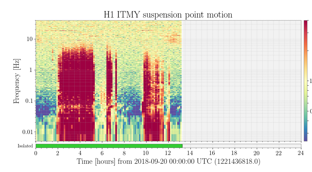
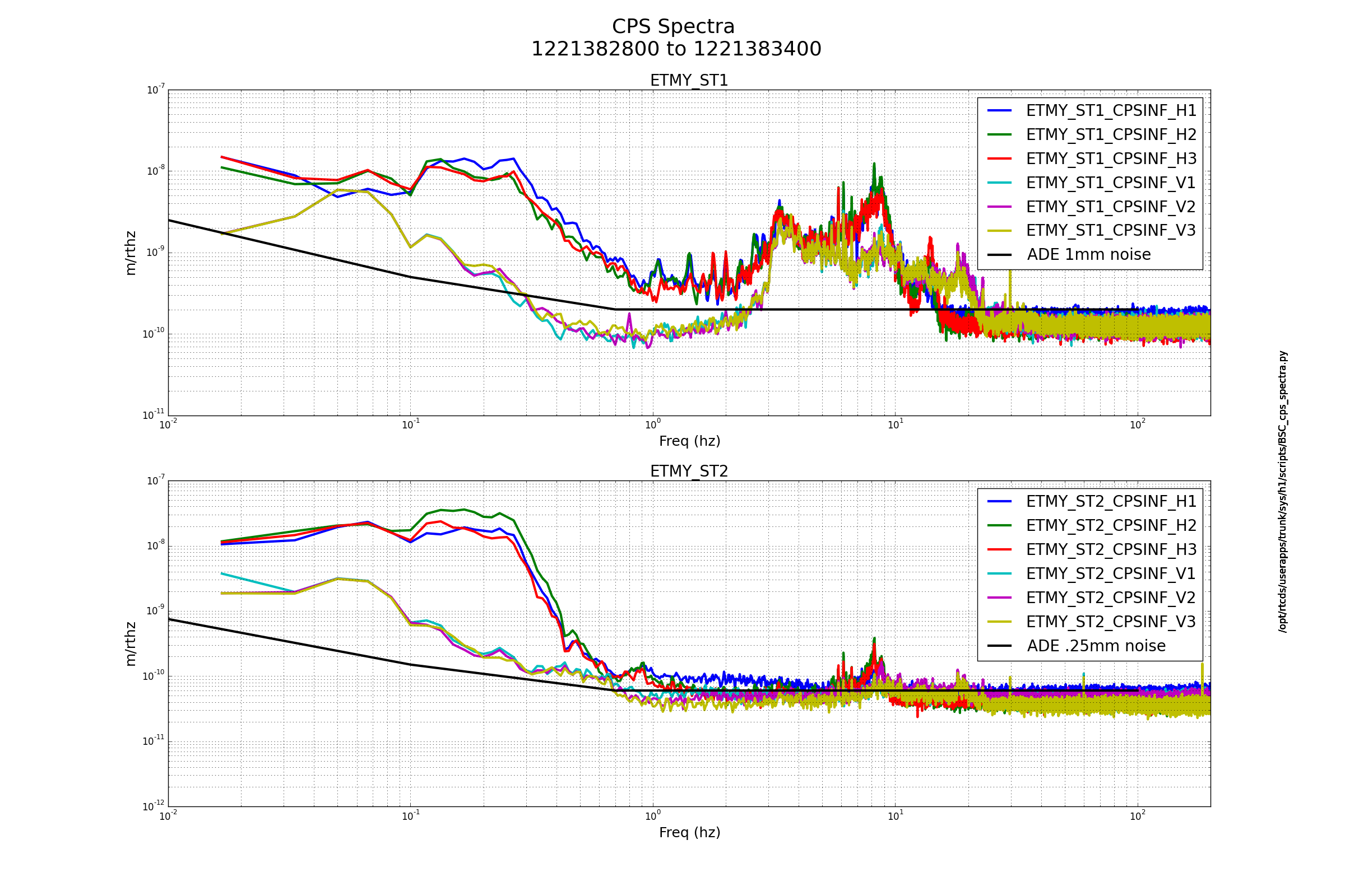
- Time glitching of the end station SUS systems
Still To Do:
Install new h1oaf1 front end computer, this is a Dolphin only machine (no IRIG-B timing or IO Chassis) which will get its timing from h1ioplsc0.


