This is to facilitate crane inspection work today.
Notes:
Attach shows the EndX wind sensors for 30 hours covering much of Sunday. I selected this period as the wind direction spent a good bit of time around our nominal direction of 90o.
The item to note on the graphs is the blue trace on the upper right plot showing the reduction of the wind measured before and after the fence fabric. When the direction is within range, the reduction is a pretty steady 50%. Same as before, nothing new.
Monday:
RESTARTING CDS:
All plots seem to be nominally sound.
APS crew is on site to try and finish off the system. They will be starting in the LVEA and working their way out. Should not take long in the LVEA and the work will not require any noisy activities.
TVo, Danny
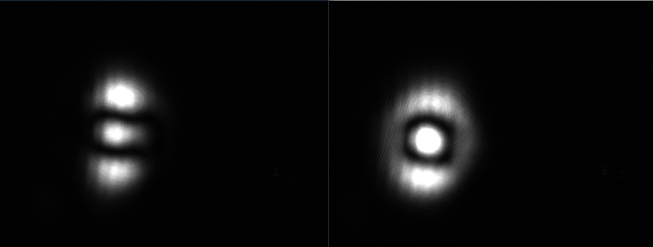
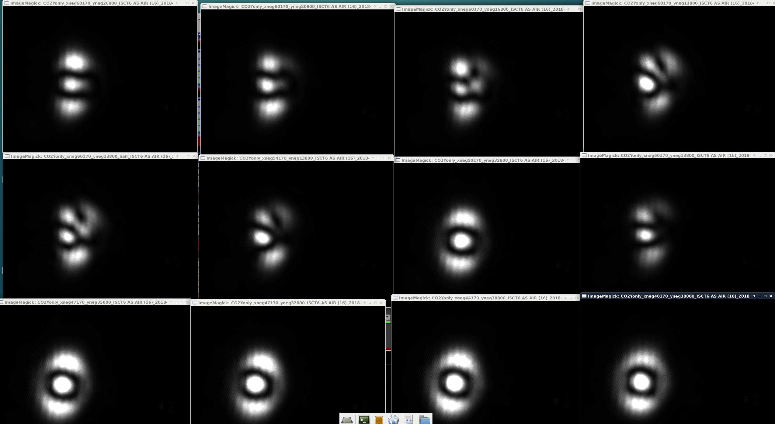
In yesterday's alog we checked to see the CO2X alignment on ITMX and today we made efforts to check and refine the CO2Y alignment on ITMY. With the guide of the HWS prism trend as well as the ISCT6 AS AIR camera we improved it as much as we could for the day (please see attached image for before and after picomoter movement). Our starting picomotor position was at X:-60170 Y:-32800 and it's current position is set at X:-40170 Y:-38800. In between these initial and final coordinates we spanned a bit of this coordinate space to attempt to maximize the amount of LG 10 mode (please see second attached image for mode photos we took throughout the day).
Contrast defect
Once attaining the best mode mismatch signal we could get (without eating up anymore time) we decided to turn on CO2X and measure the contrast defect. We got as low as 27 counts on H1:ASC-AS_A_DC_NSUM_OUT16 giving us a contrast defect of about .36%.
We attempted to make further improvements on CO2X alignment on ITMX but decided to call it a night before doing another contrast defect measurement. The CO2s are still on at the moment CO2X is at 1.55 watts central heating and CO2Y is at 1.85 watts central heating.
Danny TVo Georgia
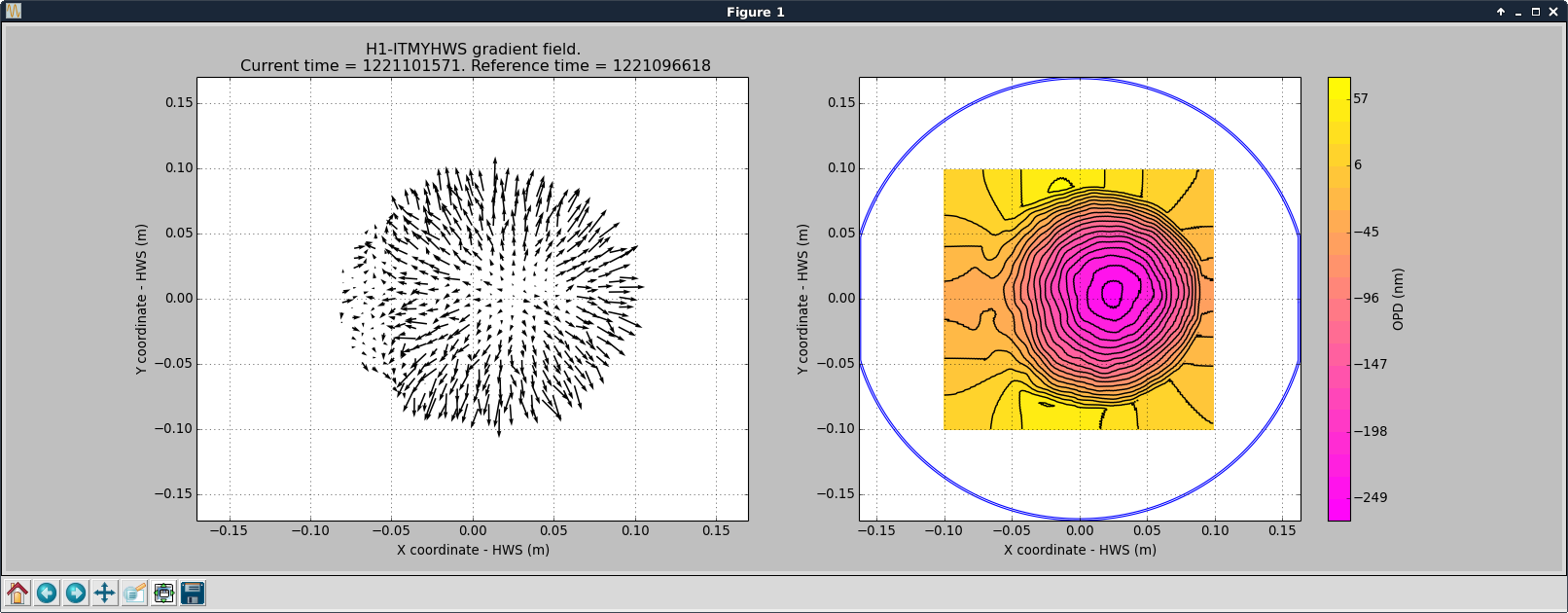
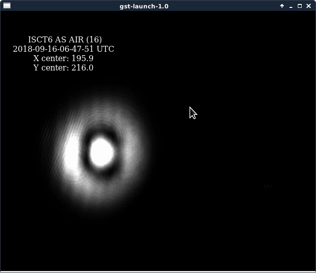
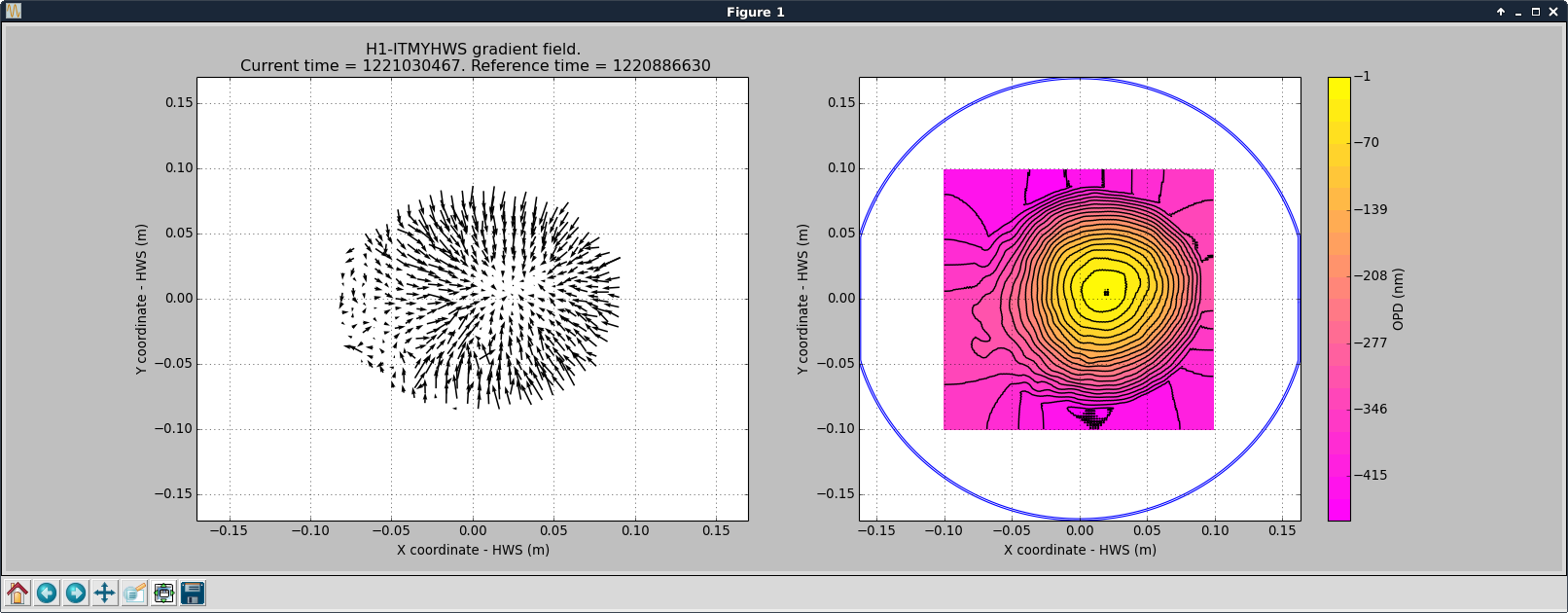
Today we decided to be more scientific about decoupling the CO2 misalignment and Michelson mode mismatch parts of the contrast defect. We turned both CO2 lasers off and waited for them to cool down (leaving the ring heaters on). The first attachment shows the AS Air camera returning to a bullseye mode. From the rates of cooling and the image on AS_AIR, we suspected that CO2X is misaligned predominantly in yaw, and CO2Y a bit in pitch. This is confirmed when we plot the contours as we cooled down and compare them to the IFO, shown in attachments 2 and 3 for ITMX and ITMY respectively. We've now turned CO2X back on, and once it heats up we will pico and look at AS_C until we return to the bullseye mode. We will then turn on CO2Y and (either today or tomorrow, it takes a couple of hours to reach thermal equilibrium) finalise its alignment in the same way. Then the only degree of freedom left to optimise the contrast defect is the CO2 laser power.
We tried to pico CO2X while looking at the HWS and the AS port with only CO2X on. We moved by -2000 counts but saw no change on the Hartmann or the AS camera (we were dominated by bullseye mode with only one CO2 laser on though). Might be good to repeat this test at a lower CO2X power, and maybe check that this picomotor is actually working.
We turned on CO2Y, according the HWS spherical power it's still reaching thermal equilibrium, the AS_AIR camera looks like it's dominated by 20 mode, if we still believe the HWS from before maybe the first thing to try tomorrow is correcting for horizontal misalignment by pico-ing CO2X and vertical with CO2Y, but I'm not really sure. Could also turn CO2X off and look only at CO2Y but again I think the bullseye will dominate.
There seems to be clipping in ITMY CO2 which was not there before, this is strange but could be the source of our asymmetric heating.
Danny, TVo, Hang (remotely)
We had trouble locking MICH_DARK because the gain settings in LSC params was too low in the locked state. We changed the acquire gain to 4000 instead of 2000, and the locked gain to 8000 instead of 2000.
Hang, Danny, TVo, Georgia
Today we worked on trying to improve the simple michelson contrast defect by positioning the CO2 lasers on the ITMs. This TCS work is ongoing and will continue tomorrow.
We can steer the beam using the periscope top mirrors. The diagnostic tools we have are the AS photodiodes (AS_A and AS_B), the shape of the beam on the ASAIR camera, and the HWS contour plots. This is an arduous task due to the long time constant of heating, and confusing results while steering the picomotors, at one point the contrast defect looked very good but we struggled to get back to that same position.
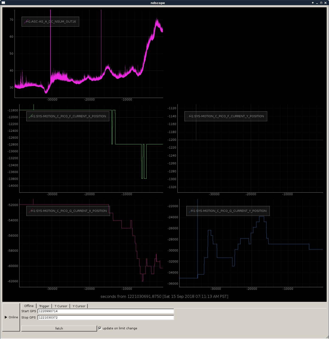
Attachment 1 shows the power on AS_A, and picomotor relative positions (not neccessarily an accurate measure of position), over the course of the evening. We looked mostly on ITMY, amd looked first at yaw and then at pitch. We take these measurements in the MICH_DARK_ALIGN state of ALIGN_IFO, and adjust the offset on the ASC MICH loop to keep the dark port dark. The lowest value we saw on AS_A was ~27 counts, but we swept through it early and couldn't repeat it.
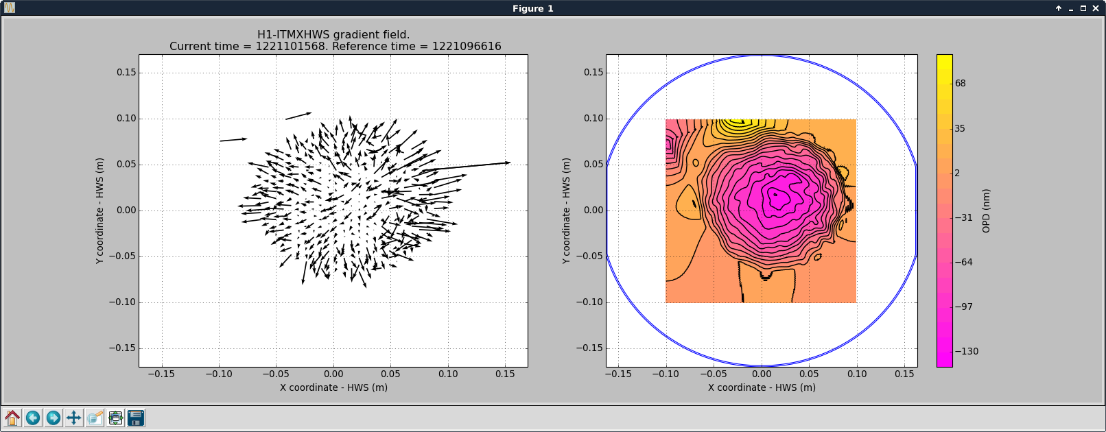
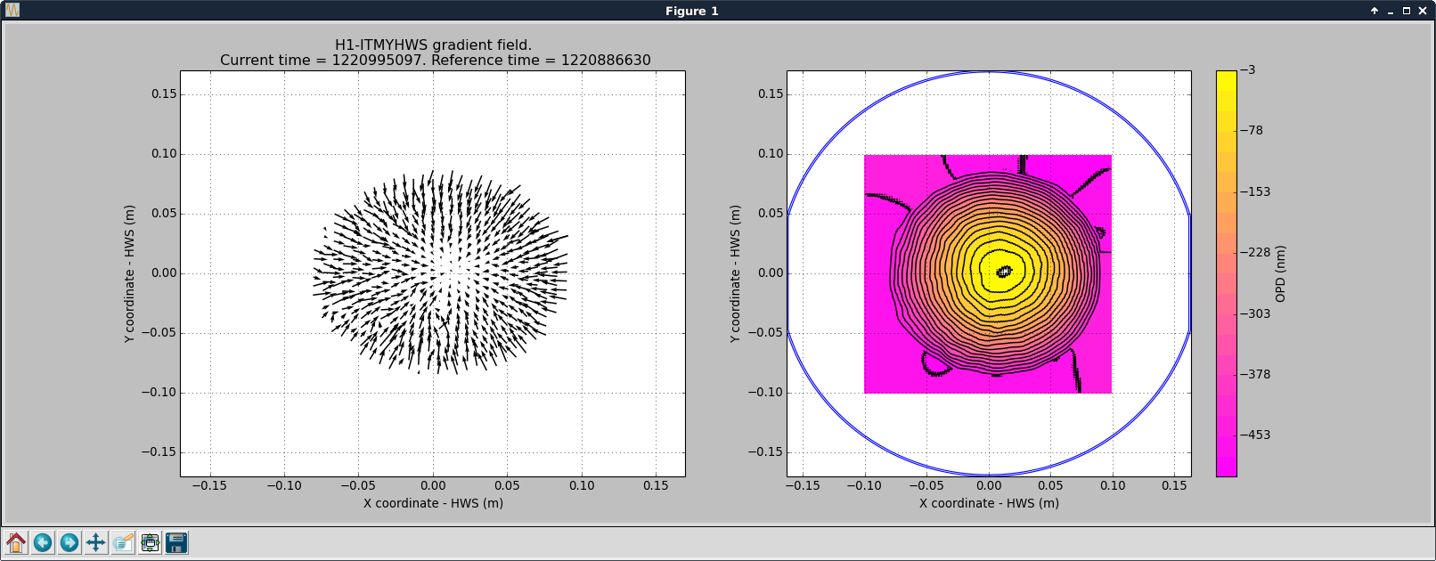
Attachments 2 and 3 are HWS images of ITMY before and after picoing (the after pico-ing might be a bit washed out as it won't be at thermal equilibrium). We're aiming to overlap the CO2 beam with the IFO beam, pictured here.
I noticed both CO2 powers were drifted by ~10 mW over the course of the day, shown in attachment 2, that might not be a problem normally, but might have contributed to us not being able to get back to optimally dark dark port?
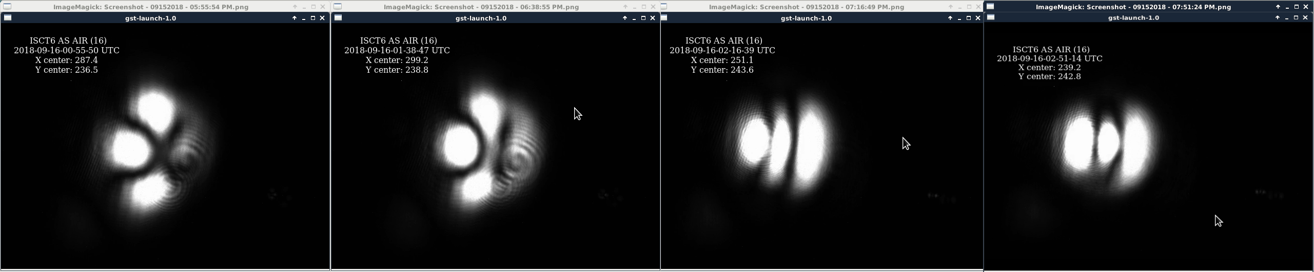
Final attachment shows the AS_AIR camera at the end of the day. I misaligned SR2 to get this image but put it back at the end of the day.
Tonight I'll run two scripts to change the CO2 laser power overnight I was going to leave the IFO in MICH_DARK LOCKED but am now having trouble acquiring. I will leave it trying to acquire.
Keita, Jenne, TVo, Danny, Georgia, Hang
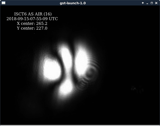
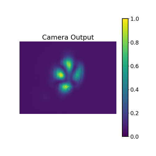
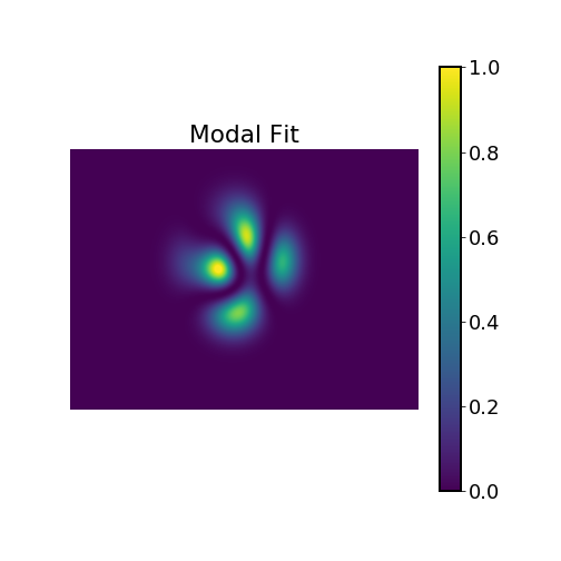
We developed a script to decompose a camera image into Hermite-Gaussian (HG) modes. Please see the attached images for an example of the code's usage.
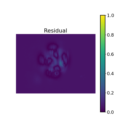
The first image showed the raw camera image of AS AIR when the IFO was locked in MICH DARK. We tried to decompose the image into the HG basis up to 4th order (that is, 2nd order in misalignment and 2nd order in mode mismatch). The second image showed the best modal reconstruction, which captured the main features of the raw images reasonably well, and the third image showed the fitting residual (the rms residual power was 0.1% of the total).
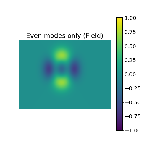
From the image we could separate the even-order higher-order-modes (HOMs) due to mode mismatch, from odd-order HOMs due to alignment offsets. For example, in this specific image we estimated that 62% of the power was from mode mismatch and 38% from alignment offset. Unfortunately the image slightly clipped on the camera which distorted some even modes into the odd ones. Nonetheless, after we fixed the camera pointing we should be able to get a better estimation of the contrast defect by subtracting out the odd-order contributions. For example, the last plot showed the even-order HOM-only part of the image, and we could see that the 02 and 20 components were out-of-phase, indicating the heating in the horizontal and vertical directions might not be even.
In addition to helping TCS tuning, the code should also be able to measure (at least estimate) the contrast defect and alignment drift for the full IFO without needing to setting up an OMC scan. Camera images should be enough for this purpose. The code might also be used to estimate the beam quality in other places.
The code is available at:
/ligo/home/hang.yu/Desktop/small projects/modeFit/modeFit.ipynb
Nice. Is there still a problem of engaging WFS in full lock?
In the past sometimes we had to manually pre-align the interferometer after CARM offset reduction before all WFS loops could be engaged. We did it by looking at the AS and REFL cameras plus DC powers (X,Y arm, SASY 90 and sometimes baffle PDs). I guess you could implement this scheme to work automatically.
It might also be possible to go further and do initial alignment by processing images from the cameras with flashing beams. Since it is possible to do it manually, there might be a way to train a script to do this.
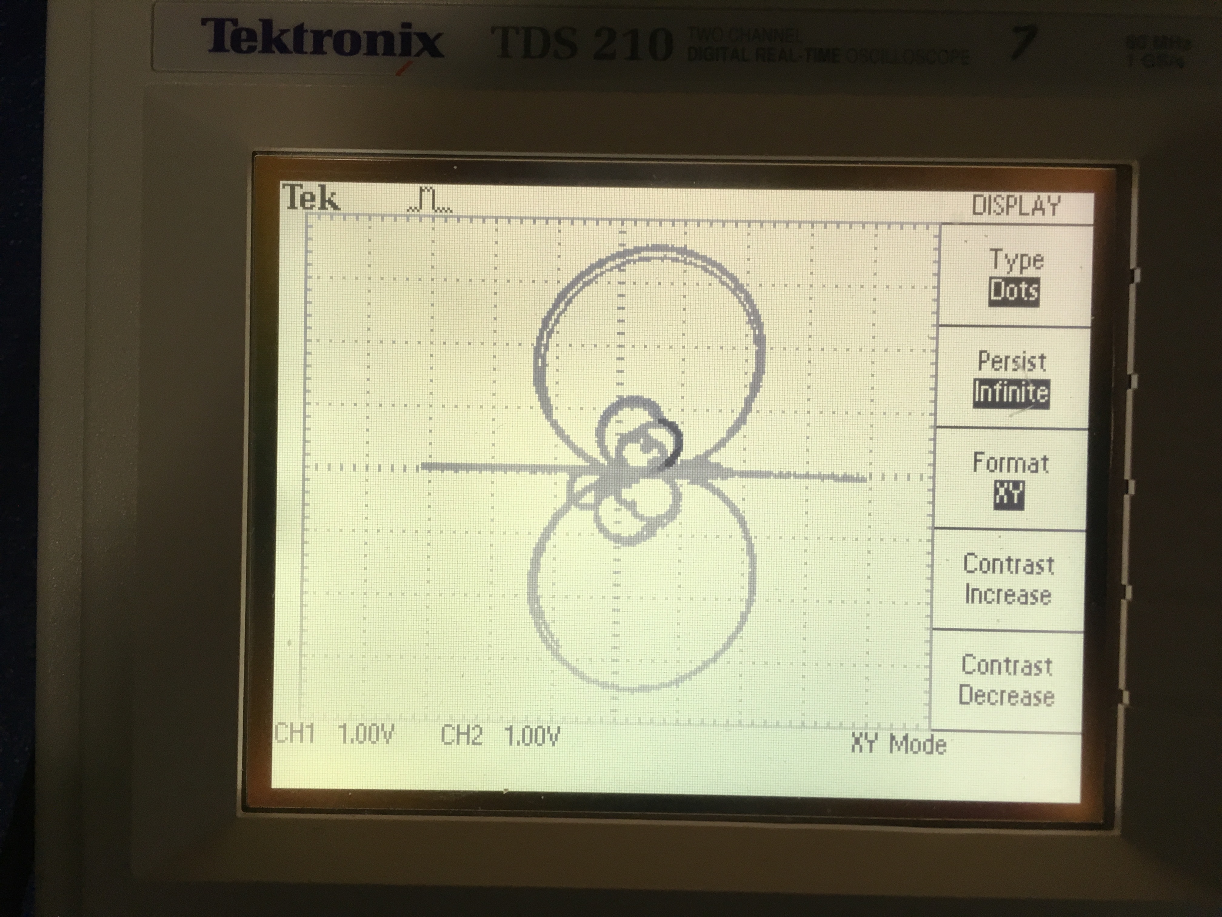
Following Daniels's comment (alog44001) I moved OPO refl diode back a few inches away from the focal point. That solved all of our locking problems. The error signal now crosses zero (and linear) at pump transmission peak, the I-Q plot looks symmetry and lopes now scale with power. The beam size that was hitting the diode looked like it was ~100um. Apparently that was too small. Now it's roughly a factor of 2-3 larger and all falls within the diode.
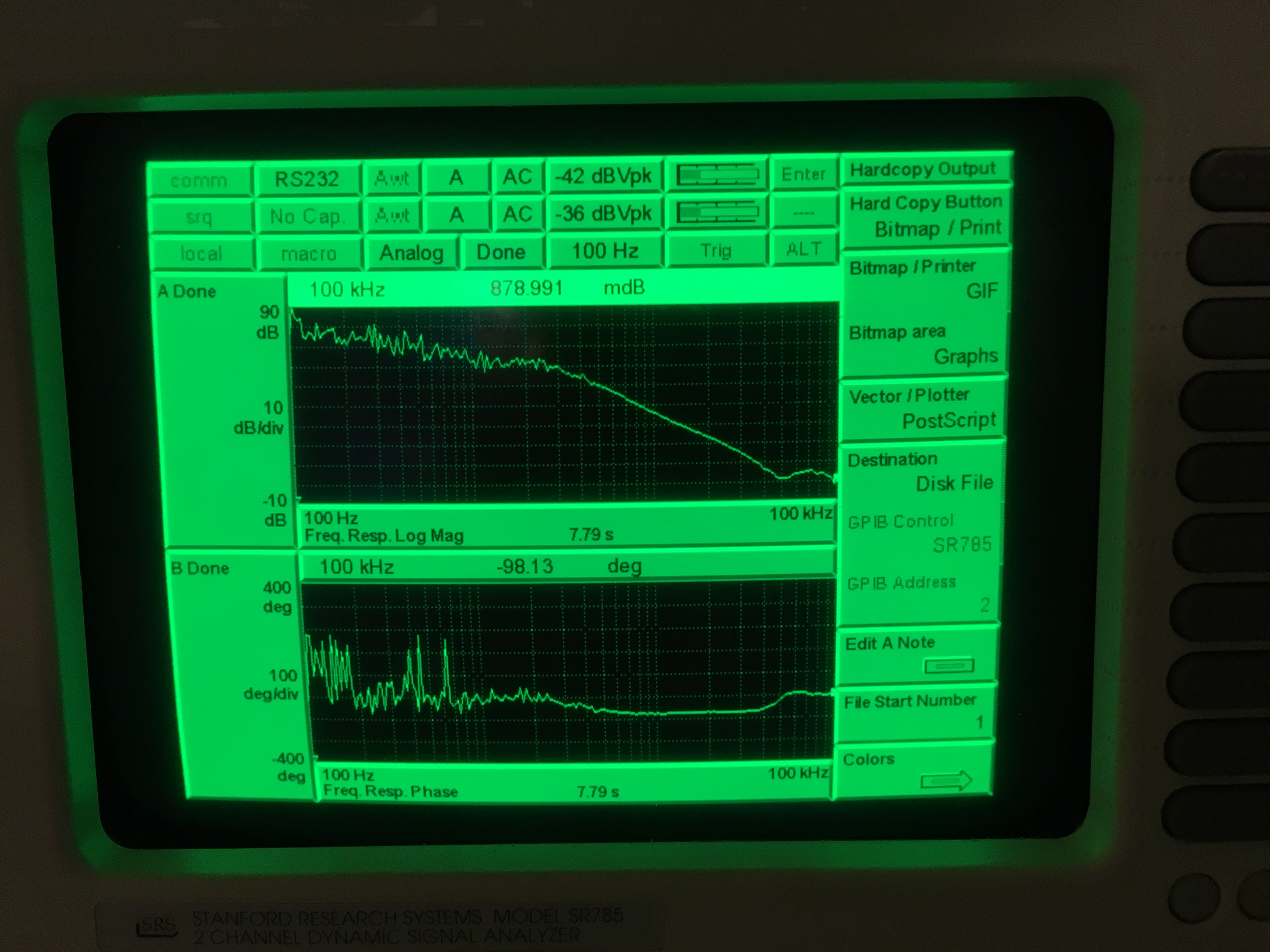
Here's a scan with ~20mW pump input to the fiber (~7mW to the OPO)


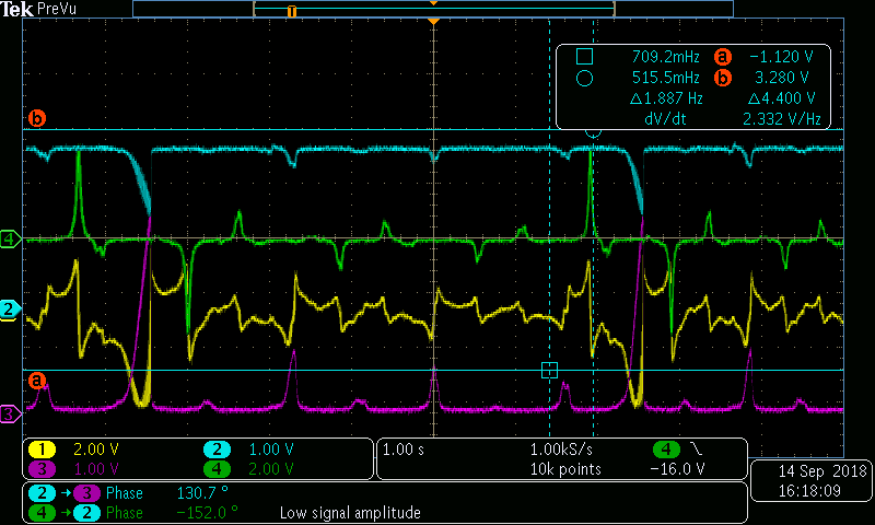
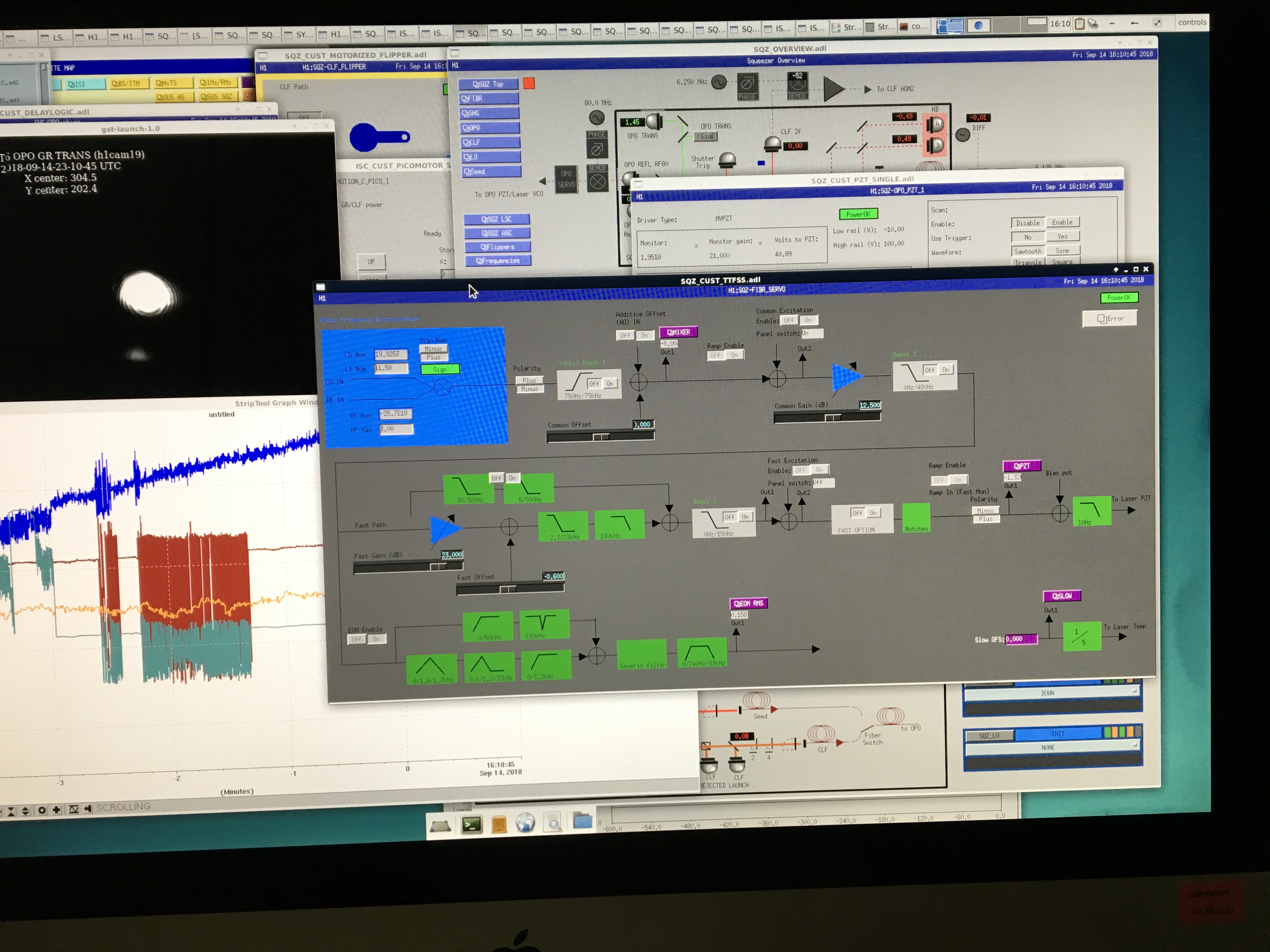
With larger error signal TTFSS UFG crossing is now a little over 100kHz. I couldn't push the gain much further without ringing something up (and boosts weren't turned on). Need to drag in a RF spectral analyzer next time.


I also put a 20dB attenuator to attenuate RF power that drives 35.5MHz EOM to check whether the 35.5MHz peak pump refl saw really came from there. SHG didn't have trouble acquiring lock so I left it there. The UGF is ~2kHz. Usually 3kHz without attenuator.
It's a wonderful Friday....
TITLE: 09/14 Day Shift: 15:00-23:00 UTC (08:00-16:00 PST), all times posted in UTC
STATE of H1: Commissioning
INCOMING OPERATOR: None
SHIFT SUMMARY:
LOG:
15:15 Karen out to LVEA
15:34 TVo out to TCS tables - checking on FLIR camera(s)
15:55 Nutstine out to LVEA - ISCT6
Ongoing TCS work: Adusting Differential lens to fix spot/mode for ASAIR (TVo, Danny)
working through All-Hands (Thanks Corey)
17:06: Tour of LVEA for A+ completed (Jeff K & Charlie T)
17:25-17:40: Trip to MY/EY for water resupply/quick clean possibly (Karen)
17:29 Haocun joining Nutsinee for Squeezer measurements out at HAM6. - both came out for All Hands
17:35-out? Making measurements (tape measure) out on the floor in LVEA (Betsy & Chandra).
20:33 Jason to MX - 3IFO stuff
20:54 performed "Load Coefficients" command on H1ASC - changes did NOT include actual filter changes as per the script results
21:00 Jason back
model restarts logged for Thu 13/Sep/2018
2018_09_13 16:01 h1sysecatc1plc1sdf
2018_09_13 16:01 h1sysecatc1plc2sdf
2018_09_13 16:01 h1sysecatc1plc3sdf
2018_09_13 16:01 h1sysecatc1plc4sdf
2018_09_13 16:01 h1sysecatx1plc1sdf
2018_09_13 16:01 h1sysecatx1plc2sdf
2018_09_13 16:03 h1hpipumpctrlsdf
2018_09_13 16:03 h1pslopcsdf
2018_09_13 16:03 h1sysecatx1plc3sdf
2018_09_13 16:03 h1sysecaty1plc1sdf
2018_09_13 16:03 h1sysecaty1plc2sdf
2018_09_13 16:03 h1sysecaty1plc3sdf
Slow controls SDF restart after relocation of h1build machine.
model restarts logged for Wed 12/Sep/2018 No restarts reported
The Xarm ITM green camera only updates about 1/second, while the Yarm is updating at more like 16Hz. I'm not sure how long this has been happening, it's been at least a few days that the green X camera has been slow, but I didn't really realize that it wasn't right until I just now looked at both green ITM camera values at the same time.
Since we use these cameras for initial alignment of the arms to the green beams, this is slowing down the preparation for starting the lock acquisition sequence. The loops are slow enough that it seems to be working as-is, but it's clear that the Yarm was ready long before the X.
I recall seeing the Xarm be slow for at least a little while now, and we've been able to lock and get the full IFO ASC going, so this isn't a show stopper, but it will certainly be helpful to have it fixed. Maybe it'll be better after next week's computer reboot fest? I'm almost done with initial alignment by now, so it's likely not worth rebooting anything for it today, unless there will be a lot of IFO work over the weekend.
Hmmm, maybe I'm changing my mind. I don't think I can trust the current camera position. It's been weird like this at least as far back as the on-disk data goes (~8 days), but clearly it has been working. But, when I let the alignment loops run, the COMM beatnote wouldn't get above -17dBm. When I open the camera loop and just use the other 2 loops and put ITMX where it was when we were last locking, the COMM beatnote is back to -5dBm where it should be.
Keita pointed out to me that the rate of update is related to the exposure rate, and the Xarm exposure is set much higher than the Yarm, so the slowness is expected (why the exposures are different I don't know yet if it's an accident or intentional). The camera setpoints were changed to reflect our latest good full IFO alignment. I had mistakenly thought that we had done an initial alignment since the camera setpoints were changed (in which case someone would have caught the poor COMM beatnote, and realigned ISCT1), but looking at the guardian states, that's not true. So, this first alignment with the latest camera setpoints is just telling us that we need to realign on ISCT1.
Team TCS has the IFO right now, but if they finish or take a break to do calculations, we'll touch up the ISCT1 ALS alignment.
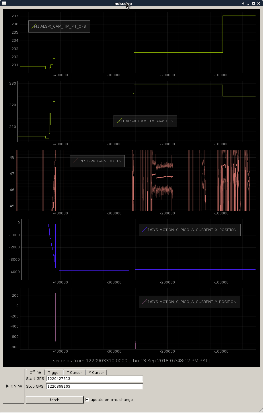
It looks like the x arm camera position was updated on Wednesday morning, but the alignment onto ISCT1 was not corrected with the picomotors in HAM3. This explains the poor comm beat note level. Attached plot shows camera references, PR gain and picomotor position over the last 5 days.
We can fix this when we next do initial alignment.