gabriele.vajente@LIGO.ORG - posted 17:07, Wednesday 12 September 2018 (43976)
Offsets in POP_RF9 and POP_RF45
[Jenne, Hang, Gabriele]
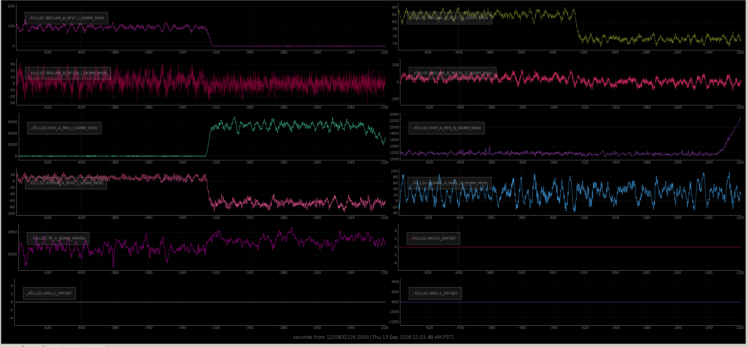
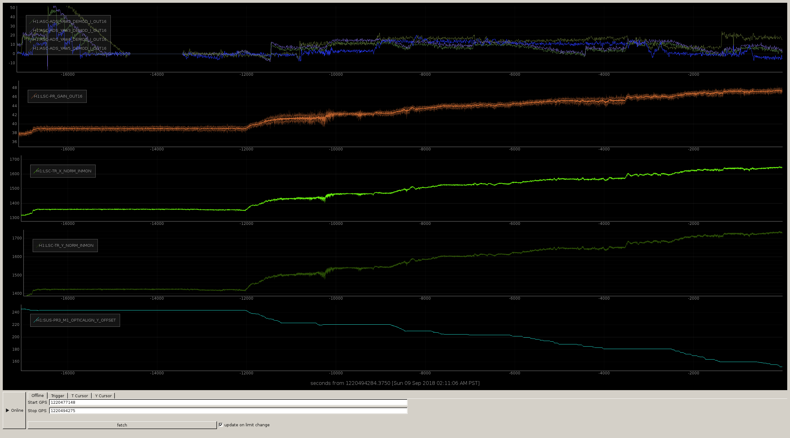
We noticed that when we switch the DRMI length loops from 3F to POP_1F, the recycling gain gets lower and less stable, like we had a longitudinal offset. Indeed before we switch the POP_RF9 and POP_RF45 signals have large offsets, in the 100-1000 counts range.
We tried to switch back to 3F after all ASC loops were on and the alignment was good, and we saw a similar behavior.
We checked the dark offsets and they are small. We also checked POP_9 phase and tuned it from -22 to -19.5.
For the moment being we don't feel like leaving those large offsets. More investigations needed.
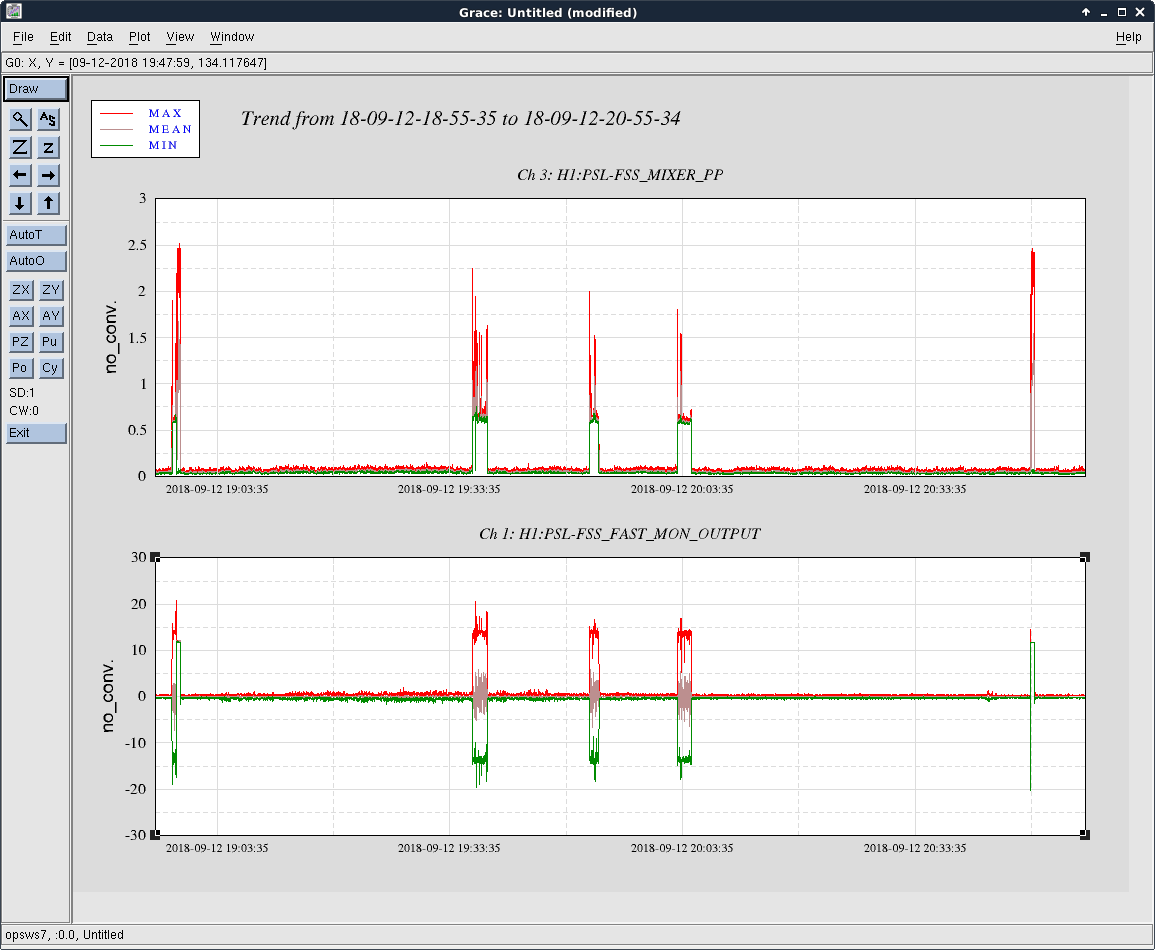
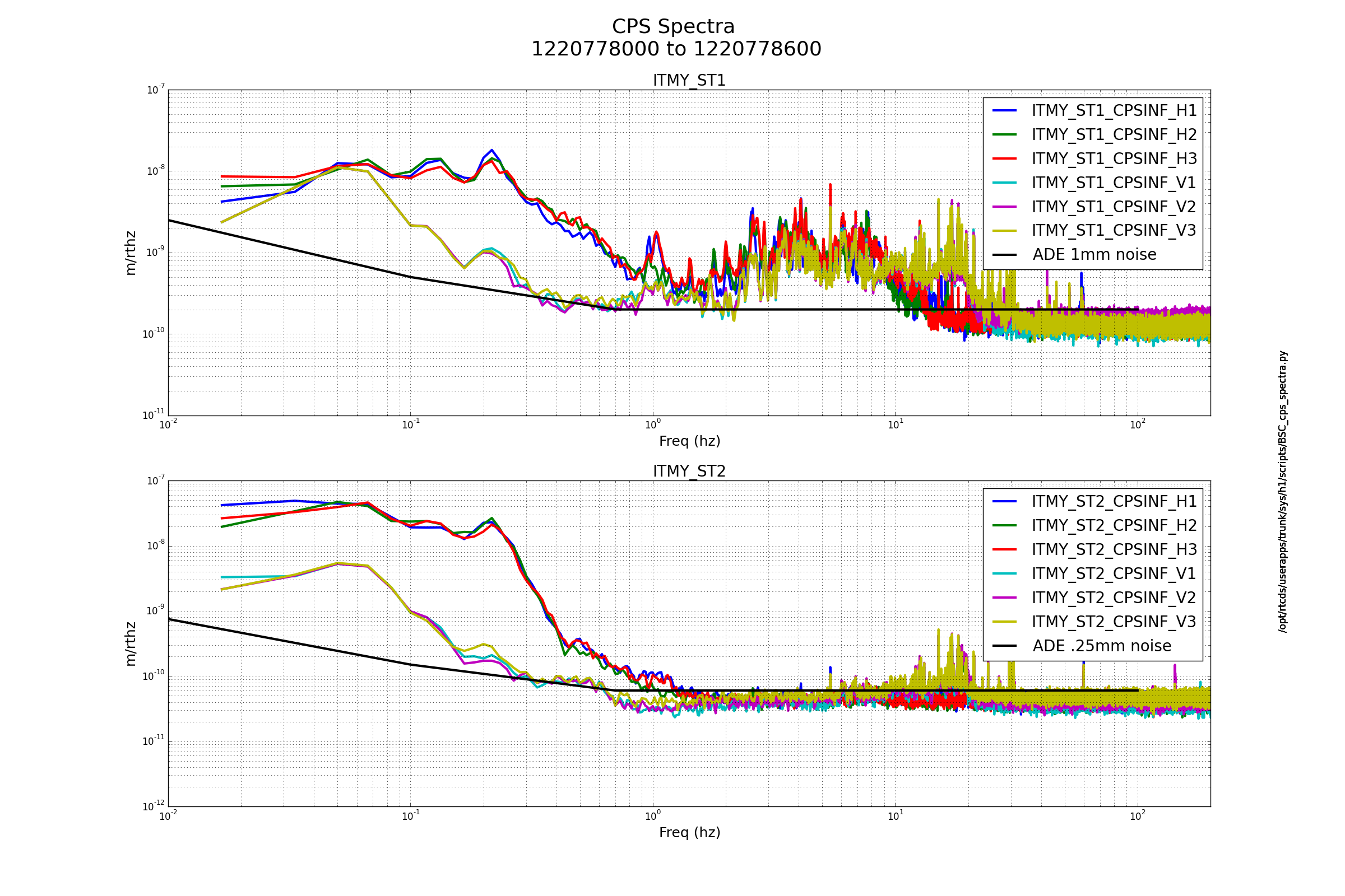
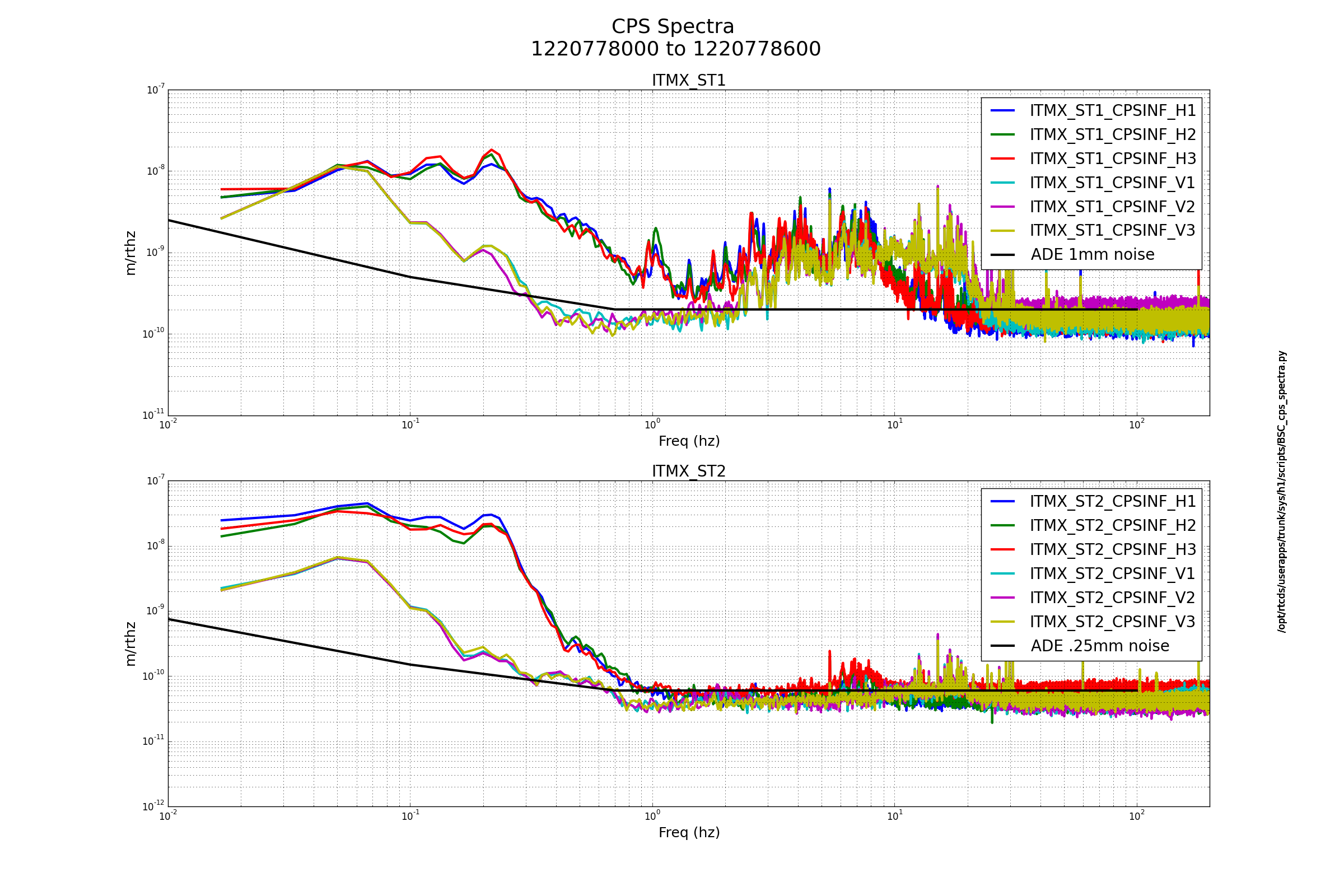
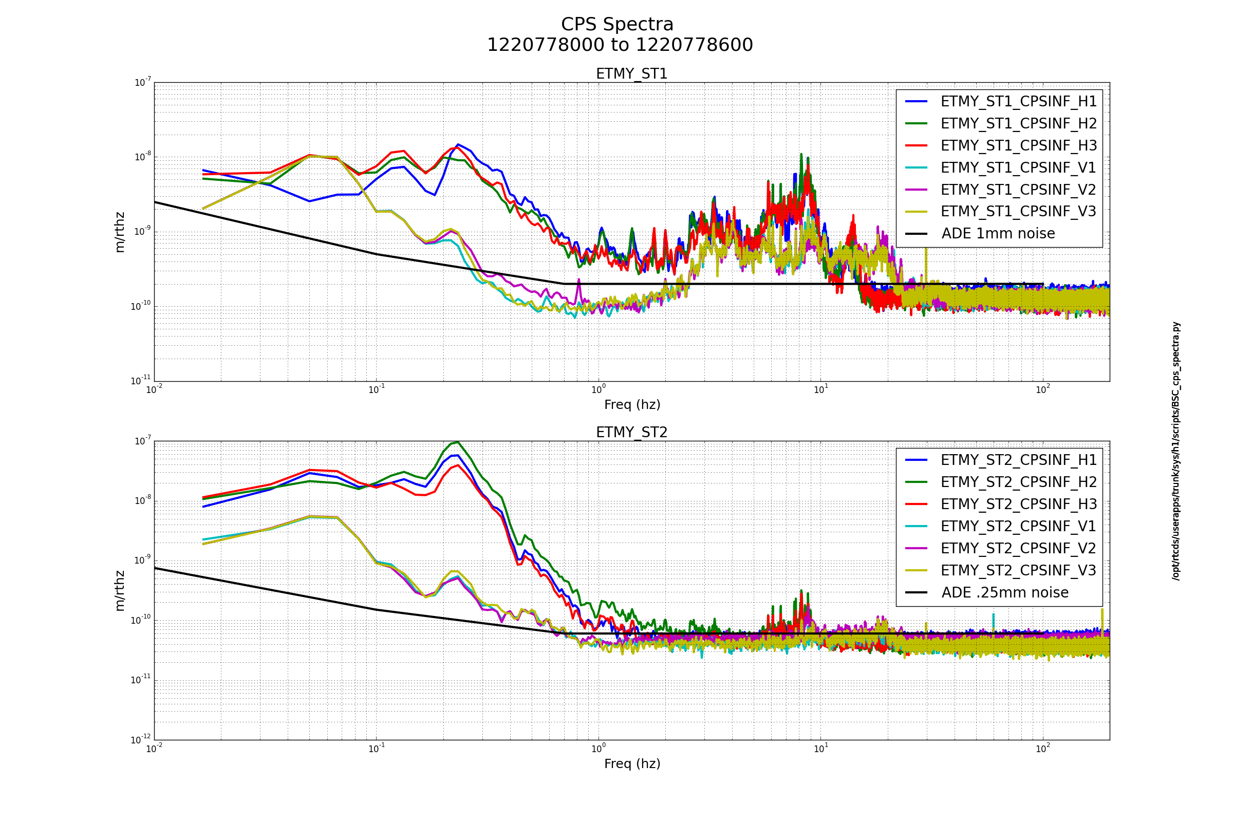
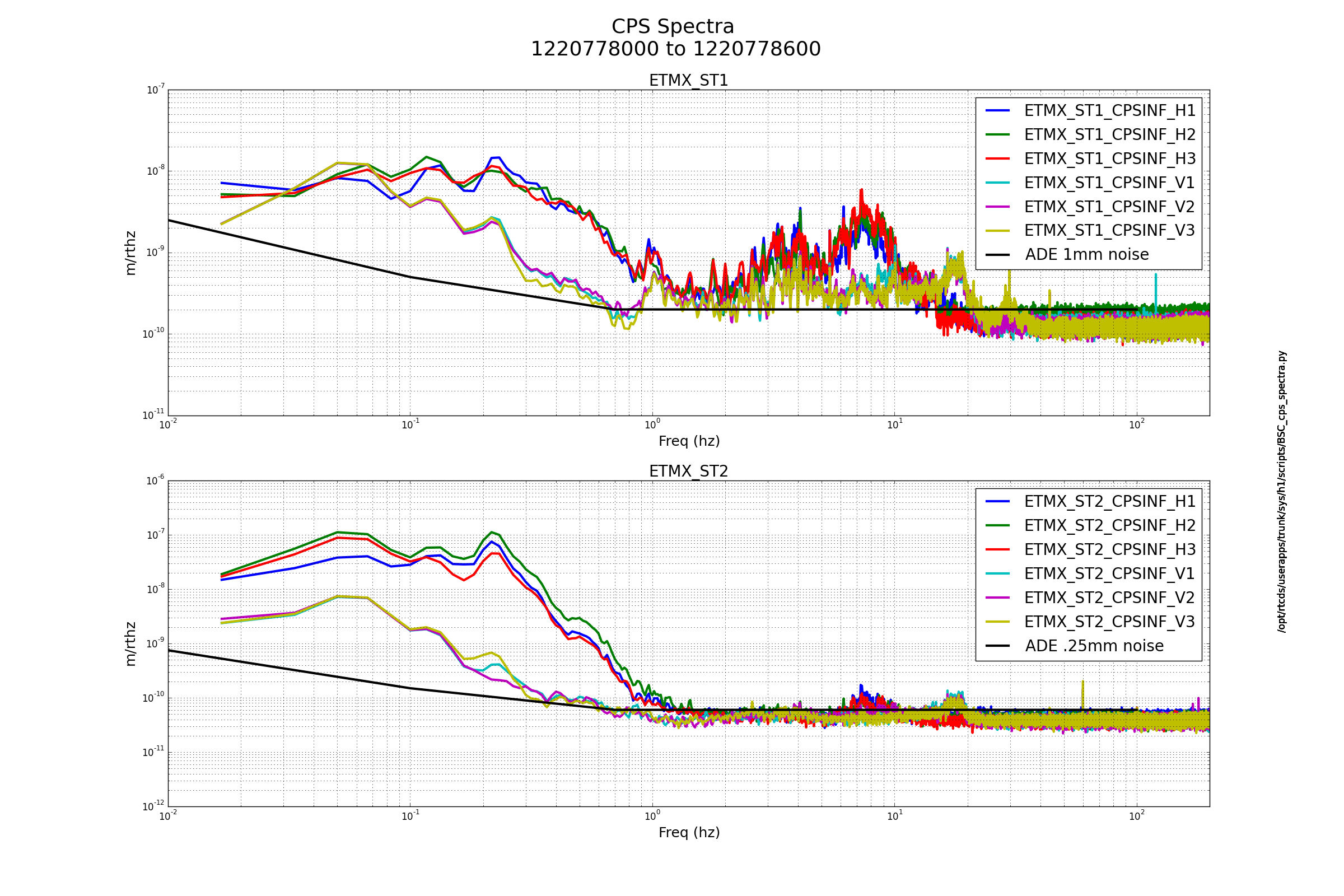
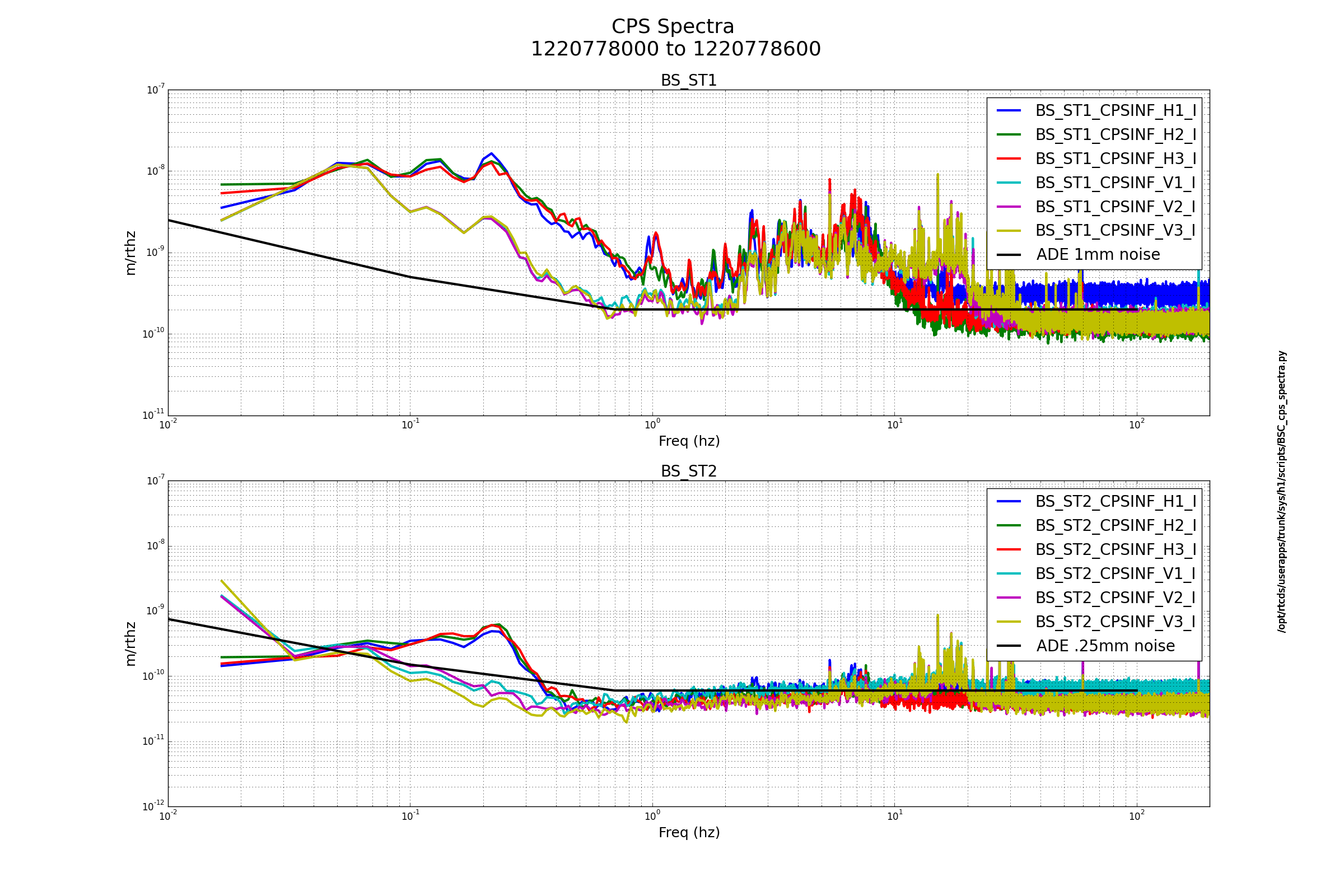
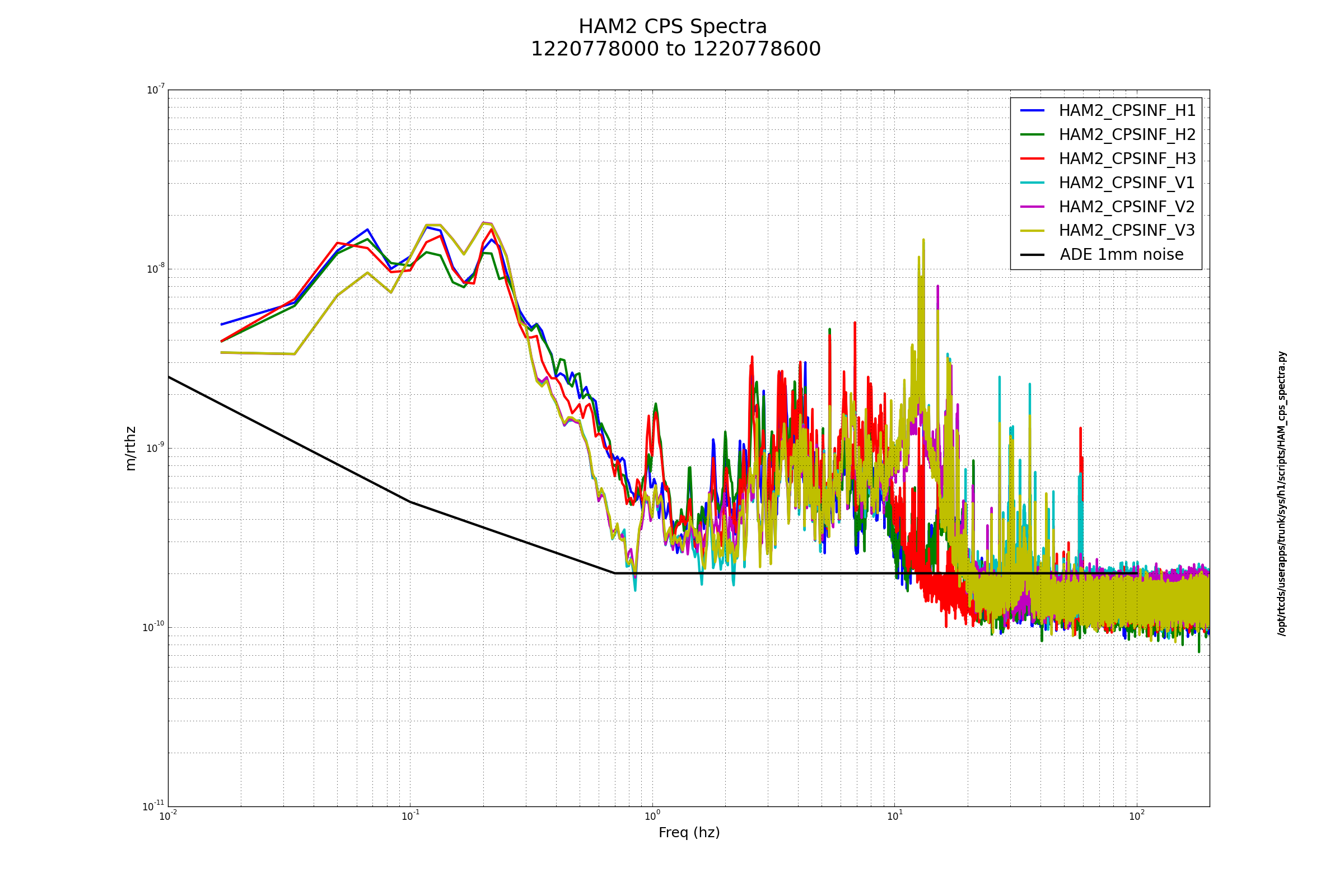
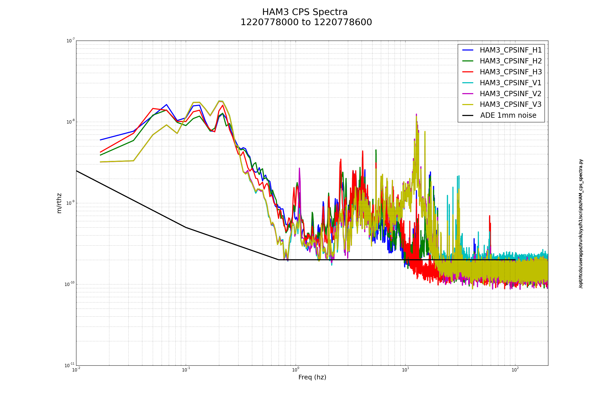
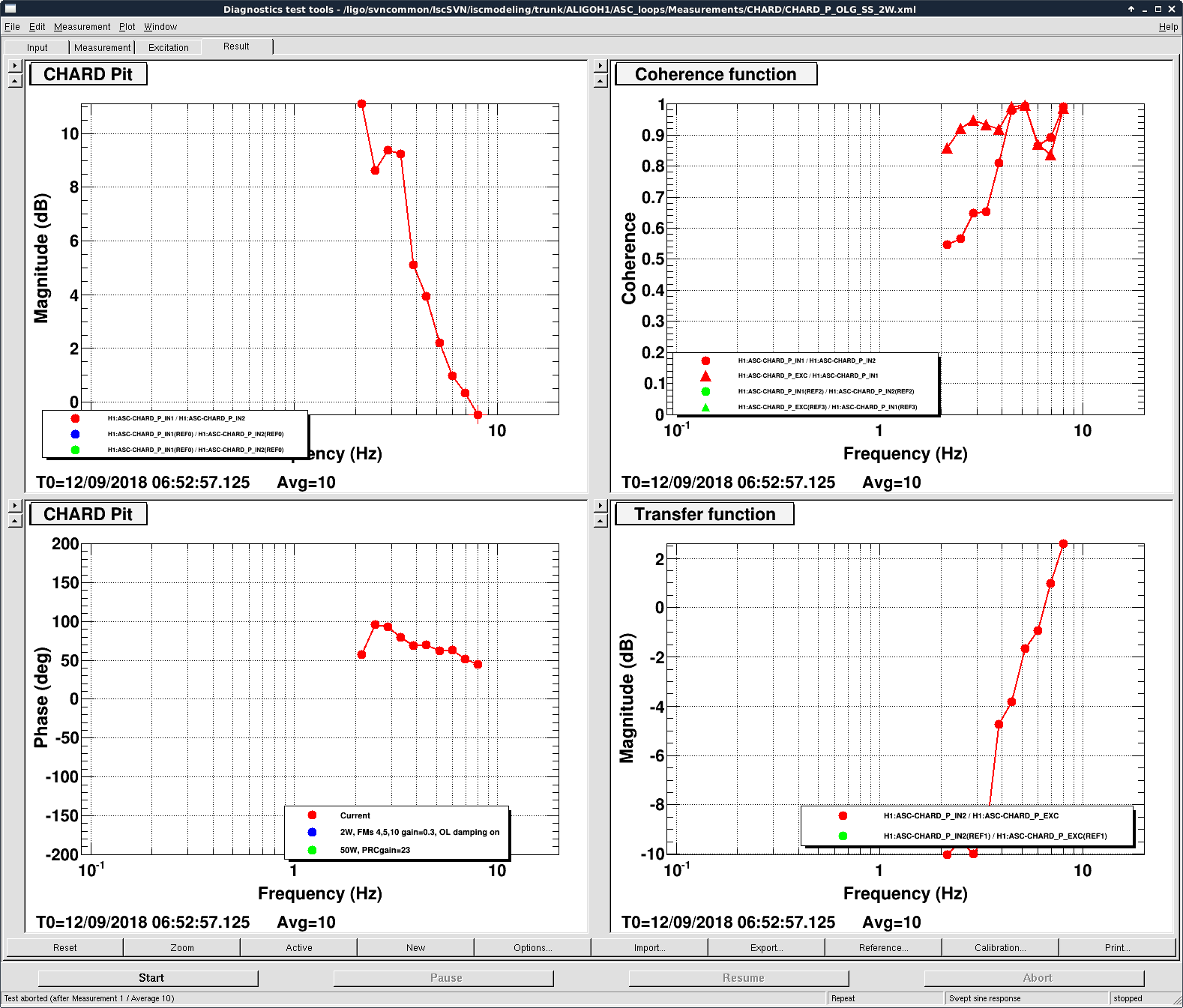
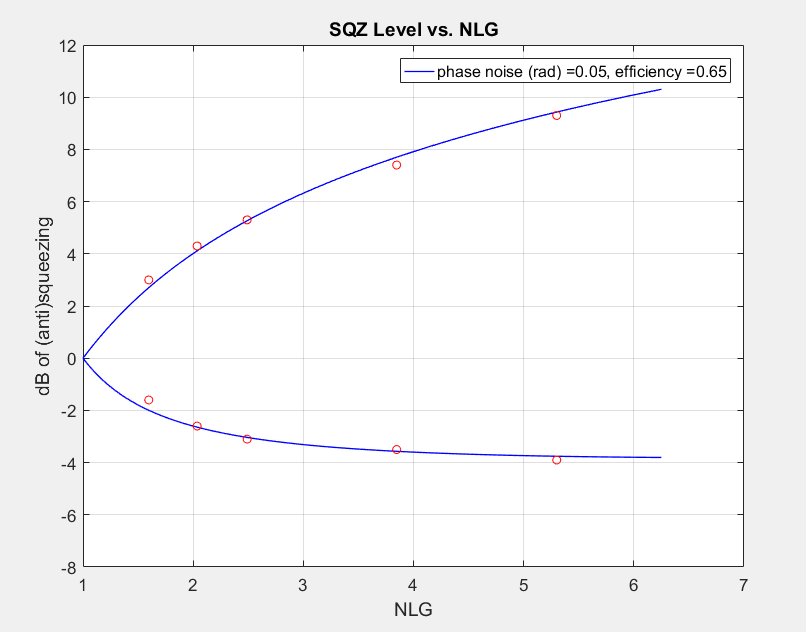
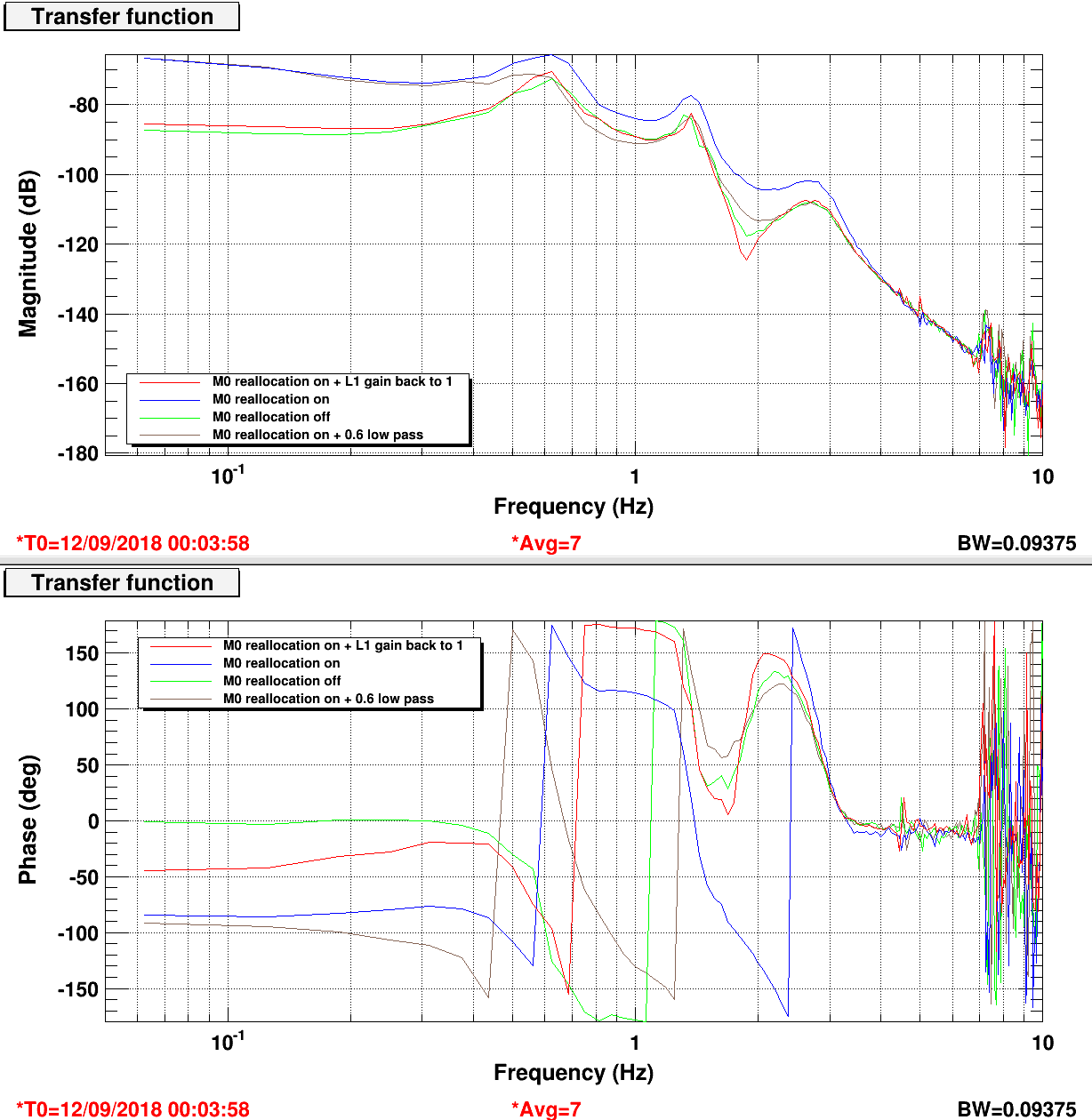
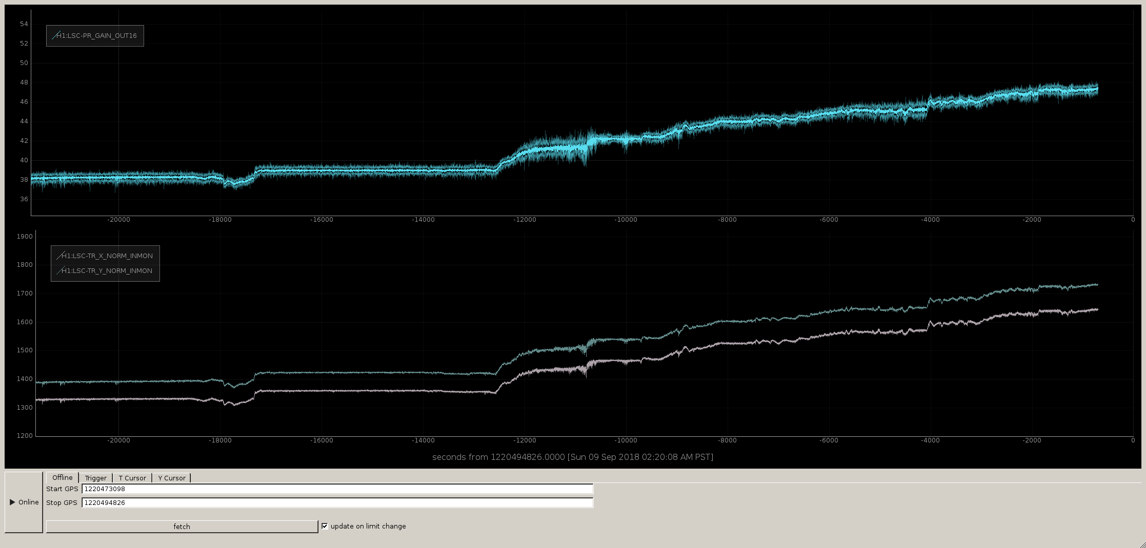
Images attached to this report