When Gabriele and I were trying to lock the IFO this morning, the ISC_LOCK guardian dead at around Sep 08 19:16:10 UTC. The symptom was exactly the same as described in LHO:43322 except for that this time it was for ISC_LOCK. It seemed to be related to some virtual circuit disconnection. We don't know what caused the issue exactly.
For now we were able to fix it by running:
guardctrl restart ISC_LOCK
I'll make a log entry when I get there
Fire pump 1 is now off, drove down both arms and checked chiller yards, all OK. One fire truck left the site as I was driving down the Y-Arm. Small activity remains on Rt. 10.
Leaving site now.
I was denied access when I had been there earlier. Was in contact with Bubba and Gerardo.
Craig, Georgia
The lightning strikes caused a fire visible from the site. It is not dangerous right now. The fire is South West of us, possibly on the other side of 240, and the wind is travelling South East (approximately). Police and fire fighters are visible, travelling on route 10.
Attached photo taken from the OSB parking lot.
(In this post I mean "railing" as "parked at the maximum actuation range", where "oscillation" means "PZT is fighting the EOM") The FSS Fast Path has been railing recently, preventing the FSS from locking. (Pic 1) It seems as though FSS_OSCILLATION does not in fact monitor the FSS RMS, but triggers on a threshold. When the FSS voltage would pass a certain value, the PSL_FSS guardian would send it to state FSS_OSCILLATING. This state brings the common gain down to -10 dB, then slowly back up to wherever it started. This works great for stopping oscillations, but not for permanent rails. I modified the PSL_FSS code to increase the oscillation threshold from 0.6 to 3 V for five seconds whenever the fast voltage is railed at greater than 10 volts with extremely low RMS. This should allow the FSS loop to close and bring the temperature within range. Railing hasn't happened again, so I haven't had a chance to test the state, but it does still suppress actual oscillations.
[Hang Gabriele]
There might be some problem with the logic of the FSS_OSCILLATION state. This morning the guardian was continuously reducing the gain to -10 db, and then ramping it up to more than +100 db. Our guess is that the self.high_gain variable which is set in the main() function got a wrong, large value. Maybe we should hard code a gain of 20 db there?
We fix the problem by stopping the guardian, setting the FSS common gain to 20 db and restarting the guardian.
For now we hacked the PSL_FSS guardian the FSS_OSCILLATING state so that the FSS_COMMON_GAIN could not exceed 20 dB. We could thus lock the IMC without needing to manually pause the PSL every time.
Specifically, we modified the original
if not ezca['FSS_OSCILLATION'] or not ezca['FSS_RESONANT']
into:
if (not ezca['FSS_OSCILLATION'] or not ezca['FSS_RESONANT']) and (ezca['FSS_COMMON_GAIN']<20.)
H1:PSL-FSS_OSCILLATION is set whenever H1:PSL-FSS_PC_PP exceeds the threshold.
More info in alog 43970.
Above comment of mine, "H1:PSL-FSS_OSCILLATION is set whenever H1:PSL-FSS_PC_PP exceeds the threshold.", is totally false, see Jason's alog.
Georgia, Keita, Craig
After Hang and Gabriele walked PR3 in yaw, this altered the green and POP alignment onto ISCT1.
We moved PICO A (controller 3) Motor 8 (ALS/POP steering HAM1) -100 in relative X position.
This put the ALS beams on the left side of the two inch periscope, and required us to move the prism and all downstream optics aligning onto TRX, TRY, COMM, and DIFF. COMM beatnote this morning was -5 dB, DIFF was -13 dB. Now COMM is -6 dB and DIFF is -6.5 dB.
Moving the picomotor alleviated Y-arm clipping somewhere in the HAM3 to ISCT1 ALS path, now our ALS_Y camera looks much better, and is not obviously scattered onto the ALS_X path. (Picture 1)
After fixing ALS, we planned to lock the full IFO however we could, return to Hang and Gabriele's optic positions, then return to ISCT1 to fix POPAIR. But this was not needed: the picomotor move ended up fixing the POPAIR alignment for us.
To return to Hang and Gabiele's alignment, we used Stefan's WFS alignment script in userapps/trunk/asc/h1/scripts. I ran python wfsreliefpast.py 1220391638, and all the main optics were brought back to where they were when they achieved higher power recycling gain.
We then touched up DRMI by hand, aligning PRM and BS so that POPAIR B was maximized like usual. We were able to lock Full IFO and get PR gain of 38 like this morning.
I was worried that after touching the picomotor we'd be falling off POP_A_LF. That is not the case (Pic 4).
We got back to the ENGAGE_SOFT_LOOPS state and continued to adjust PR3 towards negative yaw, getting even more gains, up to 38.7, first attached figure.
As we adjusted PR3 the ALS became misaligned on ISCT1 again, visible on the cameras and on the transmission DCPDs. Second attachment shows the DCPD outputs. X-arm walks off the diode and Y-arm sees more light, suggesting the beam is moving to the right on the prism (as viewed from the door to ISCT6). To reconcile the green and IR alignments we will need to pico again as described in Craig's post, but we did not get to this tonight.
We did not update the camera references, but the third attachment shows the beam position with the *inital* PR3 alignment we had at the start of the other screenshots, i.e. PR3 yaw = 247.8.
At 06:16:30 we had a lockloss that seemed to be due to a lightning strike. We've been consistently losing lock at the CARM_5_PICOMETERS state for a while now, time to call it a night.
When you moved again PR3, were the A2L coefficients of the ITMs off as we left them? If so, the demodulated dither lines values (~3 and ~10) show a large improvement (they were ~15 with the A2L off when we finished moving PR3 before the table realignment.
We also noticed that POPX PZT were railing and POPX WFS were not centered. Is it working now? If so, this explains why you were able to gain more power after the realignment, while we were clearly hitting a maximum before.
I forgot to set the A2L coefficients, so they were whatever they are after we've cycled through the down state. The ADS demod signal for one of the itms was around 4 and the other was around 10 *before* we'd done any PR3 touch-ups.
PRX was no longer railing, and the buildups on POPAIRB were still looking ok (I think by the time I'd moved the PR3 slider to 245 in yaw we were starting to lose POPAIRB again though). We suspect when we pico'd the ALS beam onto ISCT1 we also fixed the pop path, I think that's the only explanation for why POPX would be no longer railing.
Dave Barker and myself found a note on zotws17 stating that the lockloss script did not work on it. After some examination we found a bug in the version of pydv that was being used for Debian 9. The other control room workstations where not seeing it as they were using a different (possibly older) install of pydv not from the Debian packages. I put a quick fix in for the Debian 9 pydv package and pushed it out to zotws17 & zotws6 the two Debian 9 work stations.
Gabriele and Jenne commisioning. 16:11 - 16:55 UTC Phillipe and Kara to LVEA, PEM accelerometers 16:37 UTC Chris and Mark to fan rooms to install grease blocks 17:03 UTC Haocun to LVEA squeezer table 17:52 UTC Jason to mid X for 3rd IFO inventory 17:55 - 19:11 UTC Chris and Hugh partway to mid X to test wind fence equipment Jason done 20:09 - 20:55 UTC Mark and Chris to end X, then end Y to install grease blocks, then to mid stations for inventory check 21:42 UTC Craig and Georgia to ISCT1, alignment work
Gabriele, Hang
We took several MICH ASC OLTF at different stages. Please see the attached plot.
First we measured the OLTFs when the MICH was locked using AS_B_45_Q signals (corresponding to GRD states from ENGAGE_DRMI_ASC to DRMI_LOCKED_CHECK_ASC). They correspond to traces REF3 (pink) for P and REF1 (cyan) for Y. The gains were low so we modified the input matrix elements from -50 to -100 to increase the UGF to ~ 1 Hz with 50 deg phase margin.
The red (REF5) and blue (REF4) traces were measured at DHARD_WFS state. At this stage BS was locked using the AS_A_36_Q. The loop gains seem fine there. Although it seemed that in the Y loop there was a feature at 2.2 Hz in both stages (both AS45 and AS36 signal). Its original yet needs to be tracked down.
The measurement template is now in
/ligo/svncommon/IscSVN/iscmodeling/trunk/ALIGOH1/ASC_loops/Measurements/MICH_writeable/MICH_BroadBand.xml
The yaw excitation (channel 3) seems to be good enough to resolve the entire band of interest. For P we used two excitations. Channel 1 (which leads to the attached plot) focuses on the high freq >0.8 Hz part and Channel 0 focused on resolving the features around the main sus resonance.
Haocun, Terry, Sheila, Rob Ward (spiritually), Nutsinee
In this alog I'd like to try to answer three questions: 1) Can we lock at relatively high green power input to the OPO? 2) Is the loss different as we change power? 3) What happen when you scan fast enough so that the crystal doesn't have enough time to heat up (if the asymmetry is really caused by crystal absorption)?
After we looked at error signal at different power on Tuesday, on Wedsday I went and moved the crystal position left and right just to see if there're any difference in the green trans/refl/error signal. After that I moved the crystal back towards the left edge and was able to lock there while getting the nlg of 5.6 out. The day before we just couldn't lock at all at the peak of green transmission (when the crystal position was roughly around the center). What's changed?
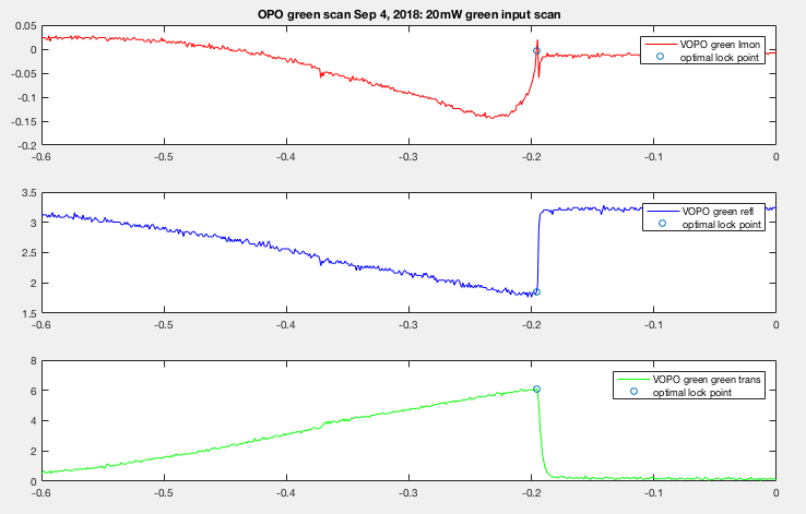
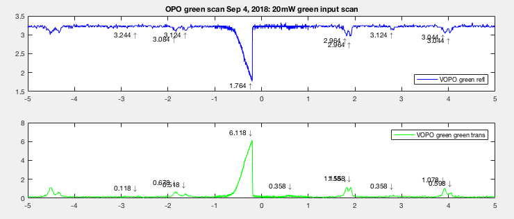
Here's the error signal between the two days. The blue circle indicate where would have been an optimal lock point (around the deepest refl dip and highest trans peak). On Sep 4th we struggled to lock on resonance. The error signal (red) seems nonlinear around the peak and it didn't take a lot of offset to throw the OPO out of resonance once you're there. We often adjusted the OPO offset just by looking at pump refl on StripTool. A lot of times it's difficult to tell if we're really on the resonance and keep moving the offset hoping to see trans becomes lower (or refl become less dippy). But in this case it would just go straight back to off resonance. Temperature change in crystal will throw OPO off resonance too.
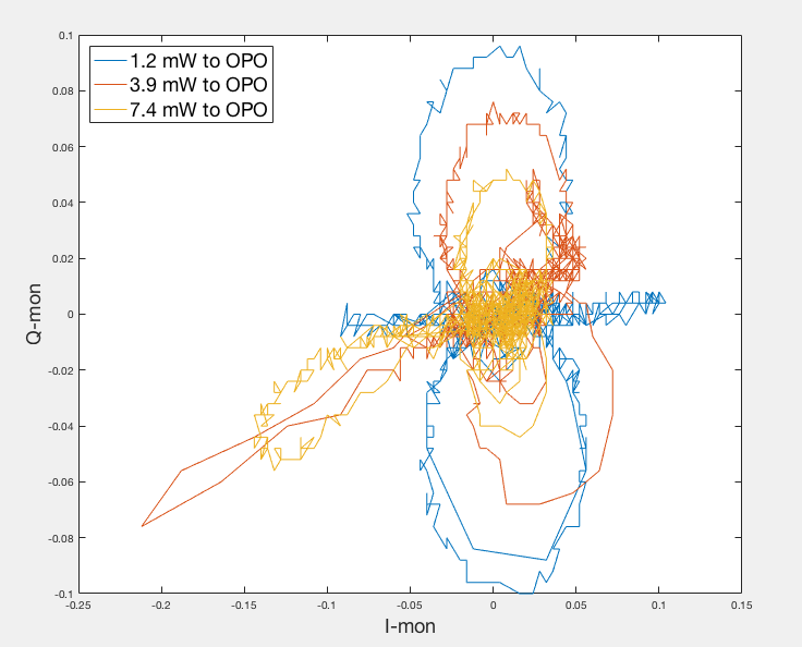
Note that 20mw green input is to the coupler. What refl is seeing is a factor of 2.7 down. So 7.4mW actually went into the OPO. The y-axis is oscilloscope Volt.

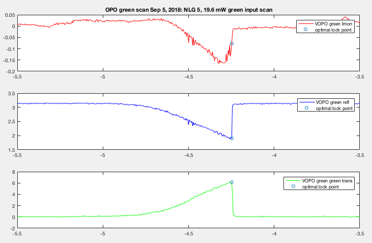
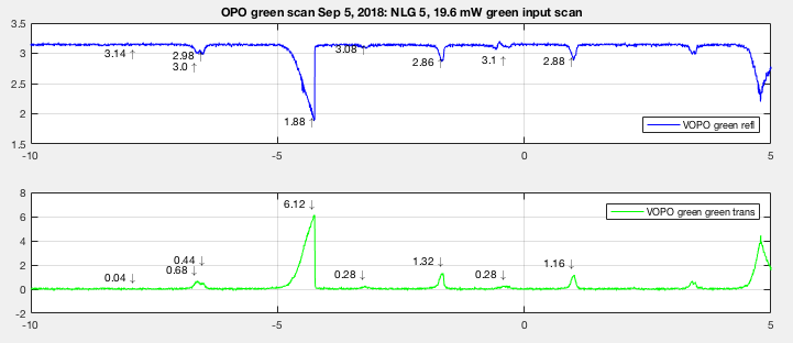
While the signal on Sep 5th seems a bit more linear around the peak transmission. Here we were able to see dip/trans signal become less optimal once I passed the optimal point to the right. This allowed us to go back and lock where we knew we had a resonance. And because of the error signal cutoff wasn't as extreme this allowed room for temperature change, which allowed us to measure high NLG before the OPO is thrown off resonance.

The estimated power loss from Sep 4th was 0.74% (50.89% mode matched), and the estimated power loss from Sep 5 was 0.46% (66.7% mode matched). So somehow on Sep 5 we have a slightly better mode matched compared to Sep 4th but less loss (more power in but less absorption? at this point I assume it comes from crystal absorption). The loss calculation has already taken higher order modes into account.
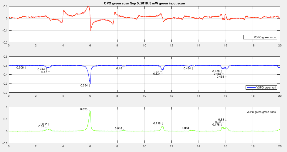
For 1.2mW input to the OPO (3mW input to the coupler) on Sep 5th I got 0.87% loss. There're higher order modes that can't be resolved at higher power so when I calculated loss for lower power I took into account the same number of higher order mode peaks just to be consistent even though more MM peaks became clearly visible. The mode match might actually be worse. I might also have taken into account the sideband which I already included in my code for rloss calculation (I just realized that after did all the calculation). This gives the loss calculation uncertainty another +-.01%. And for 3.9mW input to the OPO (10mW input to cpl) I got 0.57% loss. For how I calculated the loss, see alog43601.
So to answer the first two questions:
1) yes, we can lock at relatively high green power but the offset has to be very precise. And by "can" I don't mean "good". Maybe we have to think of getting an OPO error signal from elsewhere?
2) Yes the loss does change with input power, but it seems to be counter intuitive. at 7.4mW input to the OPO I got .46% loss, for 3.9mW input I got .57% loss, and for 1.2mW input to OPO I got .87% loss. The input power I quoted here is before the MM correction.
I also looked at the data from scanning at the left edge, right edge, and center of the crystal position. At first it seems like we have less loss at either sides of the crystal, but that's just because the mode matching became bad so less power went into the OPO, which probably result in less absorption.
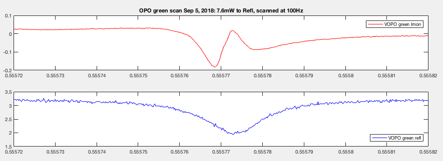
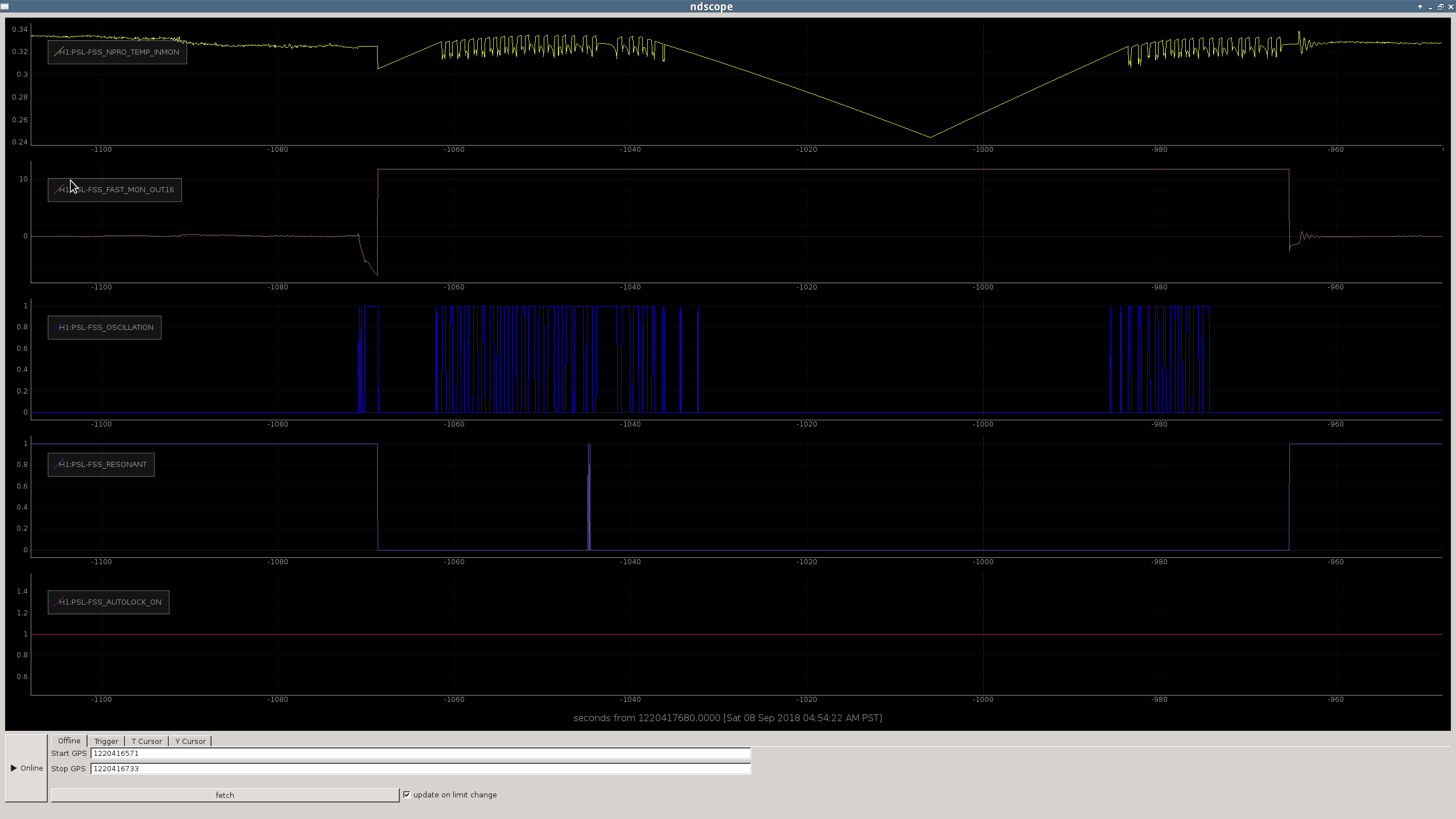
Rob suggested I scan the PZT fast enough just to see if the asymmetry effect goes away (if the asymmetry was caused by crystal heating, it should). Here's the data scanning at 100Hz. The trans PD couldn't respond fast enough but the refl clearly became more symmetry. Sadly the error signal still looks funny. The center of the linear part doesn't line up with the refl dip. We did play around with the phase, it didn't improve the error signal.

And if I calculate loss using this refl data, using 66.7% mode matched mentioned above, I got .4%, roughly agree with the previous calculation with asymmetry cutoff.
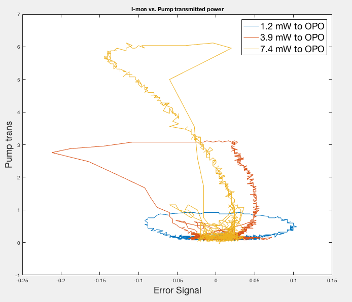
As Sheila requested, here's a plot of transmitted pump power vs. error signal, and IQ plot from Sep 4th data.


Truly bizarre behavior of the PDH signal. Notice how the sideband lopes in the IQ plot are getting smaller at higher power, when they actually should scale with the power!?
To answer the question about loss depending on power, it would be best to compare data taken at different input powers for the same crystal position.
I wouldn't expect changing the crystal position should change the cavity alignment, but I think that is the implication of what Nutsinee is saying above. In that case we should scan the cavity for several values of input power to check if the green losses depend on input power for our current crystal position. (I think that we also saved this information on September 4th, so we should be able to compare to that crystal position).
The 3 input powers loss calculation came from the same crystal position (1.2mW, 3.9mW, 7.4mW, on Sep 5th).
The PSL was rarely over-pressured during O2, which had a negative effect on the amount of dust in the PSL. We should probably set an alarm on low PSL overpressure. Figure 1 compares the particle count in the PSL during a 5-month span of time in O2, and in recent months. It is very clear that there is much less dust in the PSL when it is over-pressured. The average particle count over a 36-day interval in July and August 2018 (using only times when the PSL was void of people) was 0.165, an entire order of magnitude lower than it was in O2. So the consistent overpressure is helping. We broke this down more specifically into high-pressure (greater than .1 inches of water) and low-pressure (less than .1 inches of water) averages, which were 0.01 and 0.21 particles/ cubic foot, respectively, with standard deviations 0.32 and 2.89. A similar correlation holds between the dust in the LVEA and the pressure in the LVEA, as shown in Figure 2. It should be noted that the average particle counts published in ALOG #43253 are not correct. The average particle count in the PSL over O2 was 3.63 particles larger than 500nm in diameter per cubic foot. During the most significant dust event in O2, taking place between March 2nd and March 5th, 2017, the average PSL particle count rose up to 71.88 particles per cubic foot. Both of these numbers are still below 100 particles per cubic foot, the clean room's standard.
I wrote a script to give the names of the channels with open test points, given the FE model name or DCUID #. The old way to do this was to:
This script lives here: (userapps)/cds/h1/scripts/get_open_tps.py
I also added it to the Operator's "Useful Scripts" wiki page.
Sample output:

Jeff Kissel likes this!
USERAPPS/cds/common/scripts/cdslib.py is a python library with functions and classes for retrieving information from and interacting with front end models. In particular, it includes the function "ezca_get_dcuid()" that will return the DCUID for a given model name. If this script uses that function the user could just enter the model name, rather than having to first find the DCUID.
In fact, I recommend we just integrate this new script into cdslib, and then make a full library and cli out of cdslib, making all of this functionality easier to access.
You can enter the DCUID or the model name and then it will use cdslib to find the other. I could merge this into cdslib sometime, I like that idea.
you can now just enter the command:
get_open_tps <name or dcuid>
We should try a reboot of h1guardian1 on Tuesday.