I wrote a script to give the names of the channels with open test points, given the FE model name or DCUID #. The old way to do this was to:
- Run "diag -l" in a terminal
- > tp show DCUID#
- This would give a large amount of zeros and only a few numbers that would then have to be searched for in (target)/gds/param/tpchnnum_(model).par
- Then you have a channel name, yay!
This script lives here: (userapps)/cds/h1/scripts/get_open_tps.py
I also added it to the Operator's "Useful Scripts" wiki page.
Sample output:
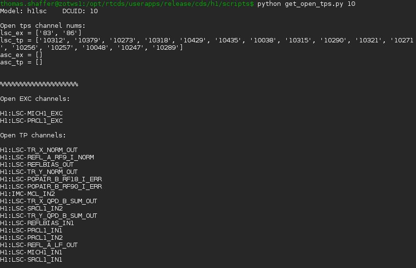
Jeff Kissel likes this!
USERAPPS/cds/common/scripts/cdslib.py is a python library with functions and classes for retrieving information from and interacting with front end models. In particular, it includes the function "ezca_get_dcuid()" that will return the DCUID for a given model name. If this script uses that function the user could just enter the model name, rather than having to first find the DCUID.
In fact, I recommend we just integrate this new script into cdslib, and then make a full library and cli out of cdslib, making all of this functionality easier to access.
You can enter the DCUID or the model name and then it will use cdslib to find the other. I could merge this into cdslib sometime, I like that idea.
you can now just enter the command:
get_open_tps <name or dcuid>