Jenne, Georgia, Craig, TVo, Hang
We parked the IFO at ENGAGE_SOFT_LOOPS and tried to center the spots on the ITMs.
Specifically, we put dither lines in yaw on the ITMs and turned off the Y2L FF gains. The lines were demodulated from DARM for us to monitoring the spots on the ITMs. We then opened the PRC1 loop (locking PRM pointing to ASC POP QPD) and used the pr3spotmove.py script at /ligo/home/controls/sballmer/20160927/ to minimize the dithering line.
We could put the spots more centered on the ITMs in the yaw direction, however the recycling gain dropped significantly to only 28. The power on arm transmission was also low, 1020 for TR_X_NORM, and 1060 for TR_Y_NORM. We tried to open the soft loops and move the soft dofs around yet did not succeed in getting the PRG back (we might not tried hard enough though).
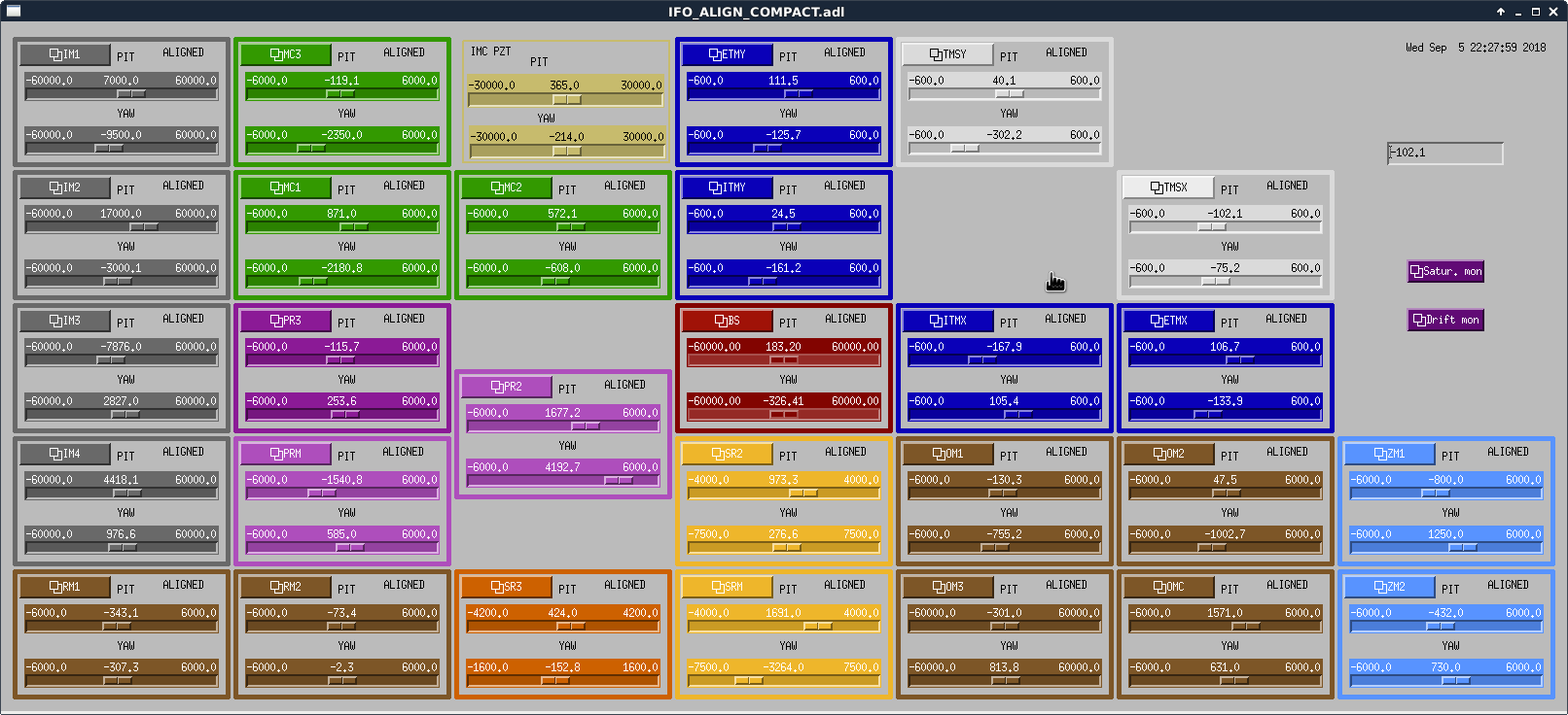
The slider and osem values for this config (spots roughly zeroed on the ITMs with low PRG). Also the ASC_POP_A_YAW_INMON value was -0.37 currently (originally +0.22).
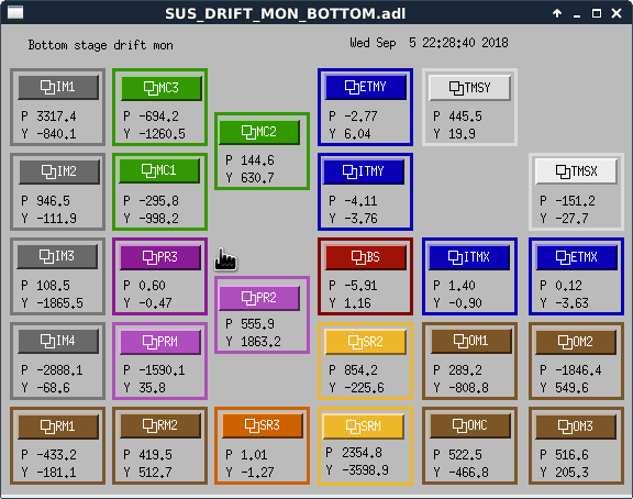
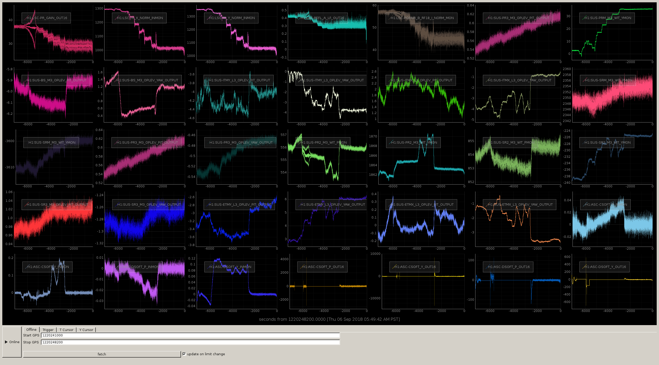
Attached a trend of mirror angular positions from witness sensors during the PR3 spot motion.
It's surprising to me how the test masses did not move in a monotonic direction as PRM did for example, but rather moved back and forth...
Edit: after further investigation, I found that the soft loops were off. I would have guessed they were still on from the statement "We parked the IFO at ENGAGE_SOFT_LOOPS".
The DSOFT loop followed almost exactly the BS motion, while CSOFT followed almost exactly PR2 motion. See second plot.