Today I had some issues with the green lock on the X arm. Almost every times the guardian went thought the LOCKING_ARMS_GREEN state, the X arm green lock was very unstable (see screenshot).
To move forward I had to stop the guardian in the LOCKING_ARMS_GREEN (or even go to DOWN) and let the X arm settle for a few minutes. Once I had to adjust the TMS pointing, since the arm was locked on the wrong mode and would not let go. Nevertheless, with this little pain, I could lock the IFO up to PREP_DC_READOUT_TRANSITION a few times.
A few times the ISC_LOCK guardian went in error. Most of the times it was one of those connection errors that I solved by stopping and executing again. Once there was an error in CARM_TO_REFL, where there was a reference to self.counte instead of self.counter. I'm not sure how I could lock a few times before having this issue...
A couple of times I lost lock because of an angular pitch instability once all loops were closed. Not sure what caused it.
I spent some time taking high resolution transfer functions with noise injections of CHARD yaw. The goal being to understand why we cannot increase the gain, as stated in many previous elog entries (43787, 43784, 43763, etc.)
The noise measurements are consistent with the sweep sine measurements. the plot below shows all three measurements together.
However, my conclusion from looking at this open loop transfer function is different from Sheila's and Craig's. My observations are
So here's what I tried
I adjusted the setpoint of the diffracted power slow servo in the ISS second loop to H1:PSL-ISS_SECONDLOOP_REFERENCE_DIFFRACTION_CAL_OFFSET = -5.32
I could then engage the ISS second loop without problems by switching on its input. No visible fluctuations in the diffracted power.
I tested once a full lock acquisition, up to PREP_DC_READOUT_TRANSITION with the ISS second loop on.
The ISS second loop can also be engaged with the IMC guardian.
Georgia, Sheila
LSC things
ASC
While we were powering up I had a quick look on the Hartmann wavefront sensors. And earlier while the A2L scripts were running I did some violin mode work.
HWS
I restarted the Hartmann code for HWS-ITMX and HWS-ITMY while we were already at 7W (one by accident the other because it had been terminated). So the references for spherical power etc are all in a warming-up state, this was mostly an accident and it would be better to have cold references.
First attachment shows the laser power, and the spherical powers measured on ITMX ITMY and ETMY as we power up. The jumps are where I restarted the Hartmann code and it reset its references.
Second attachment shows contour plots.
For ITMX and ITMY the reference time is when we're partially warmed up. The bright ghost beam has returned to ITMX. (We originally blocked this with an iris, but then opened the iris during a CO2 test and found that the reflection had disappeared). This beam seems to dominate the measurement.
The ITMY measurement seems to show heating near the center of the optic (the centre of the optic corresponds to the centre of the previous ring heater test).
For ETMY the reference time is earlier, but confusingly it looks like the centre of the optic was cooling down. Not sure how to interpret this.
I did not notice the ETMX code was not running until later.
Violin modes
I updated the monitor filters on ETMY, and updated the frequencies on the violin mode overview screen. Since the last alog on this I think we've assigned many mode modes, and put them in the table and guardian:
701.755 Hz to ITMY
503.679 Hz, 503.734 Hz, 504.176 Hz, 505.0794 Hz, 505.286 Hz, and 510.714 Hz to ETMY,
508.938 Hz, and 526.781 Hz to ETMX.
Yesterday I thought I had found the settings for 504.145 Hz (ETMY MODE6), but had trouble damping it today with the same settings.
Some analysis on theoretical estimation of the squeezing phase noise and optical loss.
The amount of squeezing and anti-squeezing levels depends on 3 main factors:
Generally, more squeezing (which is our goal) can be achieved with higher NLG, lower phase noise and lower optical loss. However, the 3 factors have different impacts on squeezing and anti-squeezing.
Given a certain practical amount of optical loss, the asqz level is largely decided by the NLG, but less sensitive to the phase noise, whereas the sqz level depends more on the phase noise amount. A high optical loss (low efficiency) ruins both of the sqz and asqz.
Therefore, given several sqz-asqz value pairs under different NLG's, we can estimate the amount of optical loss and phase noise in the experiment. This can also imply any of bias in our NLG measurements.
Summary of results from Nutsinee's measurements:
| NLG | SQZ (dB) | aSQZ (dB) | alog |
| 3 | 3.69 | 6.31 | 43764 |
| 3.6 | 3.97 | 7.56 | 43782 |
The 1st and 2nd plots show the phase noise and efficiency estimation for each group of measurement.
50mrad phase noise and 70% efficiency gives a well-fitting to these data, and based on these value the 3rd plot shows the sqz/asqz level vs. NLG.
Several reviews in the to-do-list for justify this estimation:
Craig, GeorgiaCARM
We've been having loads of CARM locklosses recently while we are transitioning to resonance. The locklosses are occurring at or just after CARM_TO_REFL, where we transition from TR_CARM to REFLAIR9. Since we are sitting at 5 picometers CARM offset when we make this transition, REFLAIR9 is very noisy, but we move to RESONANCE immediately after. I measured the TF between TR_CARM and REFLAIR9 and increased the sensing matrix element for REFLAIR9 from 2 to 3, and increased the REFLBIAS gain from 50 to 86. We have made it through this transition every time now, but the PR_GAIN number on the striptool still spikes, meaning the POP_LF power changes rapidly through this transition, which is probably bad.ASC
CHARD We tried increasing the CHARD gain a couple of times to find the thresholds of instability at 2 watts. Our measurements of CHARD suggest we should be able to increase the gain from 0.3 to 3 for both loops, but this has not been the case. We turned off all the vertex loops and the SOFT loops to remove as much cross-coupling as possible, leaving on only DHARD and CHARD. We then increased the CHARD gains: CHARD_Y was stable at 2, but not 3. CHARD_P was stable at 1, but not 2. We then tried reengaging the vertex degrees of freedom. We got through PRC1, INP1, SR1, but lost lock when reengaging SRC2. Should have reengaged MICH first :/ DSOFT vs SRC We had at least three locklosses tonight when reaching ENGAGE_SOFT_LOOPS. In particular, we found that DSOFT Y is strongly coupled with SRC1 Y and SRC2 Y, and when engaged with the new higher gain (5, old gain was 0.5) we'd lose lock. (Pic 1) We are able to engage them with high gain by hand. We increased the ENGAGE_SRC_ASC convergence waiting time to a minute, and lowered the gain for both DSOFT loops in the guardian so we won't lose lock here, but we can handle more gain once DSOFT has converged.Higher Power
We are able to stably sit at 7 watts input power, times in plot 2. We were here for over an hour while I fumbled around trying to take a CHARD P measurement. I was unable to do so: any amount of coherence achieved also caused the interferometer to be unstable.
Well, 3.969 but I'll call it a 4. Anti-squeezing 7.6 dB, nonlinear gain 3.6, fringe vis presumably 98%. I didn't adjust.
I haven't had a chance to give Haocun's code a try so here's a screenshot from SR785. I like SR785...
I also double checked the 3MHz error signal before the demod. Even at <10uW CLF the signal looked like it was nearly at saturation (peak to peak was only ~300-400mV).


OPO offset shenanigans
Today I spent some time investigating the offset issue that causes OPO to lock at its suboptimal place. Because of the asymmetry cutoff when we operate at relatively high green power (~3.5-4mW into the cavity) the error signal would cut off and crosses zero before the transmission reaches optimum. As mentioned in another alog the common offset slider bar can be used to put the OPO in the right place. However, the success rate of doing this seemed to be depended on what temperature and what green power we're operating at. Given 20 mW going into the fiber coupler (corresponds to about 4mW into the OPO), at below and above phase matching temperature (arbitrary set to 33.5 C and 34.5 C) I can lock with an offset without issue. At phase matching temperature (33.88 C) it took me three attempts. This test was done at the same green input power and same gain setting with seed/clf blocked. I also noticed that when I switched from seed to CLF after a nlg measurement the lock point of the OPO went back to the suboptimal place. It seemed to be very sensitive to temperature, that makes nonlinear gain measurement and optimization challenging (OPO did jump back to its suboptimal place a few times during nlg optimization, but it was possible to optimize, so I think our nonlinear gain measurement has been correct). Note that the amount of offset from optimal lock point did change with pump input power. The higher power, the more offset.
With OPO locked at the highest power we can throw into the fiber (20 mW). nonlinear gain of 3.6, I went and took another squeezing measurement. That's how we ended up with 4dB (maybe that new LO notch filter helped a bit, but probably not as much as increasing the pump power). I did not check the balancing or the fringe visibility since we still got the same amount of squeezing this morning compared to last night I thought the alignment must have not drifted much.
To get more squeezing at this point we will have to optimize our green transmission from ISCT6 to HAM6 feed through. Last time Haocun checked we were down from 76% transmission to 52% transmission.
*random thought* maybe it's worth looking into one of the view ports to see that we don't have green scattering/clipping. I don't know why would nlg dropped from 15 in air to 5 in vac. The green beam on the camera also doesn't look that round. Although that could just be the band pass filter in front of it.
Also I left the green input power to fiber coupler at 20mW. I didn't adjust the gain in OPO guardian so the auto locker won't work at the gain set by guardian (-9dB). The gain needs to be -24dB and the first boost can't be turned on.
Marc, Nutsinee
First image from the SR785 is what we have (Q=0.3), the last image was what we first came up with (Q=1). Marc ended up having to short R2 (the 50 Ohms) for it to work somehow.... Haven't looked at the new LO transfer function but I was able to push the gain further before PZT rung up. Good for now. We didn't use LLO's design since out LO PZT doesn't have 29kHz resonance.
Sheila, Georgia, Craig, Gabriele
We have a low bandwidth with our CHARD Y loop, from measurements we have taken so far we should be able to increase the gain, but we have not been able to do this. Since we think this loop (or DHARD Y) is the cause of our difficulties when we try to increase the power, we decided to make a long measurement of the loop.
The attached plot shows that this loop should be stable to with a factor of 10 more gain and the boost engaged. The same is also true for a factor of 10 more gain and the boost.
Increased the soft loop gains (updated in the guardian state ENGAGE_SOFT_LOOPS)
DSOFT pitch from 0.5 to 5
CSOFT pitch from 0.42 to 5
TITLE: 08/31 Day Shift: 15:00-23:00 UTC (08:00-16:00 PST), all times posted in UTC
STATE of H1: Commissioning
INCOMING OPERATOR: None
SHIFT SUMMARY: All commissioning, all day.
LOG: See attached .txt file.
We have had BLRMS channels for the BRS and tilt subtracted end-station STS for a while, but we haven't yet put them on a wall FOM. JeffK made a suggestion in https://alog.ligo-wa.caltech.edu/aLOG/index.php?callRep=43213. I'm making a slightly different one. Attached image is my low freq DMT template. The top plot is the .03-.1 hz blrms for both endstation BRS, middle are the .03-.1 hz blrms for the endstation beamline supersensors (thick red and blue) & (unsubtracted) STS (thin red and blue) and the ITMY Z STS (black). The bottom plot are the (I'm assuming minute trend?) max wind speeds for the end and corner station. All three plots are 24 timeseries for the channels, but the DMT channels are for 48 hours, so the plots could be extended.
I like this because it lets you see most of the <.1hz information we have, disambiguates tilt and displacement and shows the performance of the BRS subtraction. I don't like how many traces there are on the middle plot and the skinny lines are hard to make out, but they are mostly the same information as the the top plot. I would like to use this to replace the wind plot that we have on the wall, then we could free up space on the current low freq wall blrms screen.
Working on getting squeezing measurements and calculation from digital channel (Homodyne DC_DIFF) with scripts instead of SR785 screenshots all the time. (This answers the question from Jeff after today's noon meeting.)
This will also help us with lower frequency squeezing information that Georgia suggested.
Some first version matlab code can be find here
The plot shown is an example with 3.1dB SQZ and 6dB aSQZ.
Also going to look into the predicted optical loss and phase noise from the squeezing information (NLG, Green power, squeezing level) and measurements we already have.
[Team TCS]
Last night we ran a low power (0.5 W to upper and lower RH stages) long duration (3 hours) ring heater test on ETMY.
The ETM deformation is visible on the Hartmann wavefront sensor, and the change in spherical power is similar to an identical test we did on ITMY two nights ago.
The prism x and prism y values, a measure of the wedging seen by the HWS, indicate that there is some misalignment from the center of the optic, more in yaw than in pitch. This is shown in the middle plot of the first attachment.
The second attachment is a contour plot, comparing a reference time just before the ring heater was turned on, and a "current time" once the prism values had reached a steady state. The hole in the middle might be because I did not reset the frame rate after starting the Hartmann code?
Edit: The hole in the second plot is due to the scaling, set in the plot contour script. I've rerun the script on the h1hwsmsr computer, where TVo has added an autoscale option, the result is attached as the thrird plot.
Awesome!!! That hole is a bit odd though, I don't see how the frame rate would affect this. Changing the frame rate should only lead to longer/shorter exposures.
We found that the ITMs have a factor fo 2 more gain in the top mass L damping loop than the ETMs do. We want the suspension responses to be the same for the ITMs and ETMs so that our HARD and soft ASC loops are decoupled, so we are planning to change all of these to a gain of -1.
This morning I had a quick look at the photodiodes in the ISS photodiode box. Before doing anything
I noticed that the diffracted power chart on the MEDM screen displayed a large (many percent) difference
between the minimum and maximum diffracted power. The REFSIGNAL slider was at -2.02, which is the value
I seemed to remember where it was left last night. PDB is used as the in-loop sensor.
The DC output of PDA was measured with a multimeter to be -11 V. MEDM reported a value of 5.02 V.
Which is inconsistent with the REFSIGNAL setting. At this point ~2.8 W was diffracted. I also noticed
that the output of the quadrant photodiode was quite different from what I remembered the previous day's
reading was (that's just a feeling, not an absolute fact).
I asked Richard to check the DC power supply that powers up the AOM driver. It reported as being fine.
I power cycled the AOM driver but the behaviour did not change. The position of the beam on both PDA and
PDB checked out okay. The AOM driver checked out fine about a month ago when problems with the ISS were
observed before.
At this I would say that the problem is not related to optics, and that there is something intermittent
in the AOM signal chain.
Trend data for the AOM drive for the past fortnight is attached. There is a large excursion from ~midnight the 24th (06:40 8-25-2018 UTC), followed by one after my work on Tuesday. The electronics were not worked on, on Tuesday.
At the moment, the second loop ISS output enable switch is enabled without the first loop mis-behaving.
This is different behaviour to how things were as recently as yesterday afternoon.
Trend data for some signals suggest it might be worth looking at the op-amps N20, N22, N29, N31,
N39, N30, N2 and N34. With perhaps the most likely candidates being N32, N29, N2 and N34. As I recall
the board does not have a silkscreen so identification of the chips requires a bit more than a cursory
glance.
Haocun, Sheila, Terry, Nutsinee
3.6dB squeezing, 6.3dB anti-squeezing, non linear gain = 3, fringe vis 98%.
(screenshot of squeezing and anti-squeezing relative to shotnoise).


Today we balanced the homodyne with 1mW of seed, optimized our fringe visibility (98.5% on PD1 and 97% on PD2). CLF started off at ~10uW, and temperature was optimized for the best non linear gain. We hooked up a spare phase delay to CLF to give us more range of relative phase to play with. With this we got 2.5 dB.
Later I went back to check on the error signal on scope XY plot. it wasn't elliptical (more like an elongated stop sign shape). Sheila suggested this was due to saturation. So I lowered CLF power going into the fiber coupler even more until the shape was elliptical. I didn't look at what 3MHz peak looks like. But it was enough to lock both LO and CLF. I probably could have lowered the LO if CLF wasn't saturating the demod board. I didn't check.
We needed more phase delay so hooked up the one for OMC to CLF. So right now CLF phase delay comes from CLF phase delay box, spare box, and OMC box. This gives us a little more than 180 degree (combined with HD). CLF and HD phase delay alone can to a little less than 90 degree.
OPO lock offset is still a problem. I suspect this could be due to the asymmetry cut off of the error signal that probably cuts and crosses zero before the transmission reaches the maximum. This can be fixed with a gain slider in the common path. Still need to find out of this offset is consistent every time or if it scales with power. Then probably let the guardian take care of it in the long run.
By the end of the day we ended up with 3.5 dB squeezing. Terry's rough calculation suggested we have a lot of phase noise. It's noise hunting time.
Here's the phase delay setting for the best squeezed, anti squeezed measurement:
(squeeze)

(anti-squeeze)

Next on to-do list:
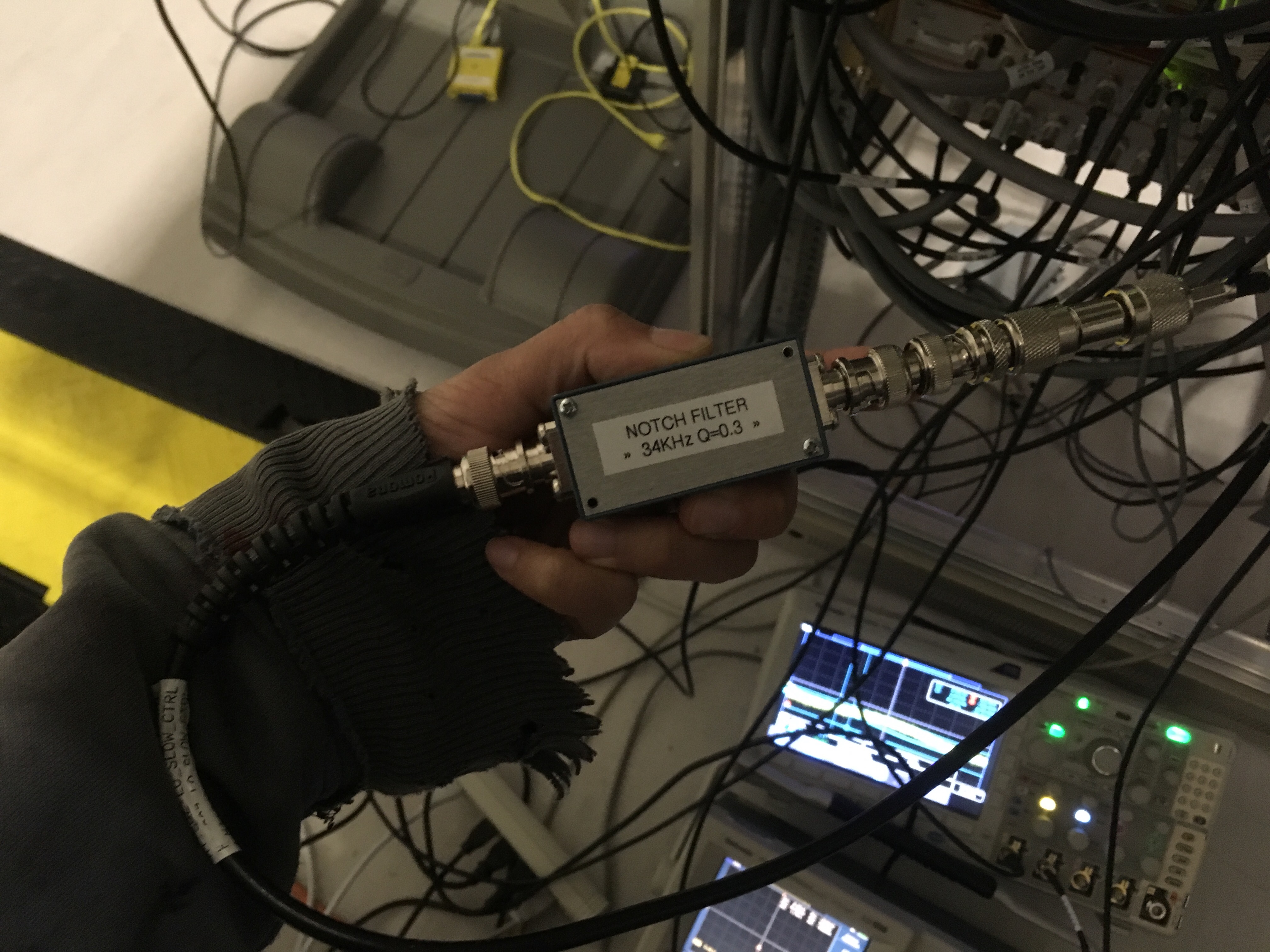
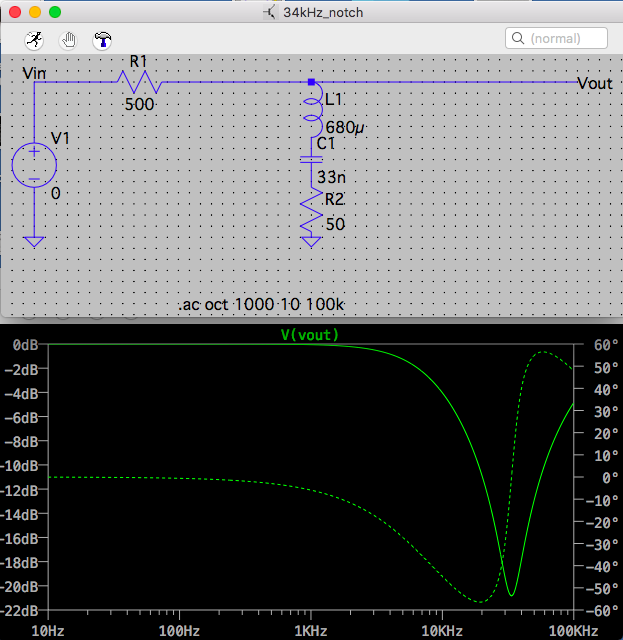
- Install 34kHz notch. With this we can push to squash LO noise some more.
- Install the modified TTFSS board to lock mephisto to OPO.
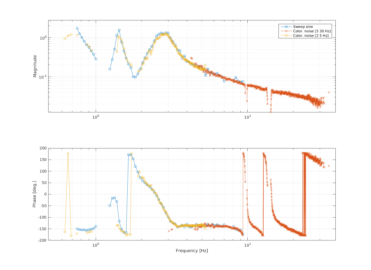
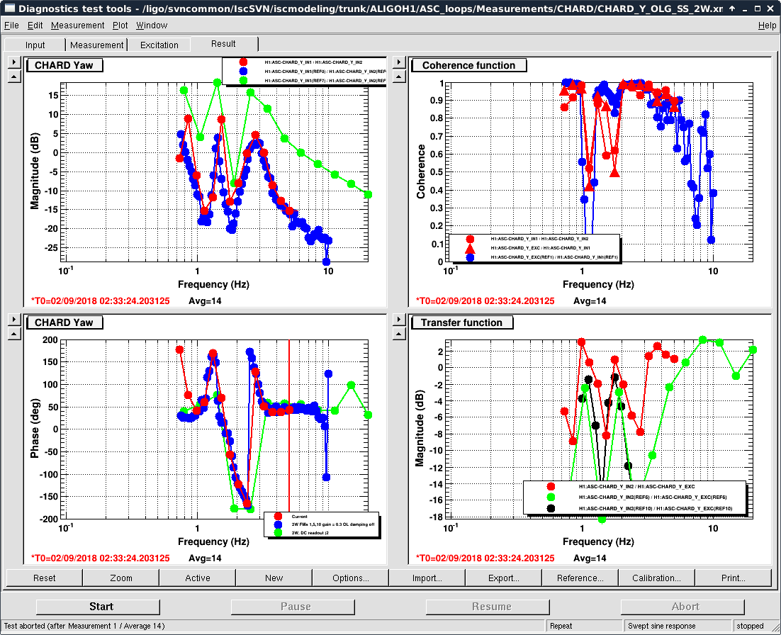
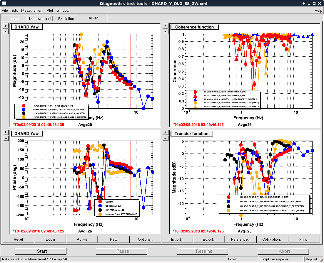
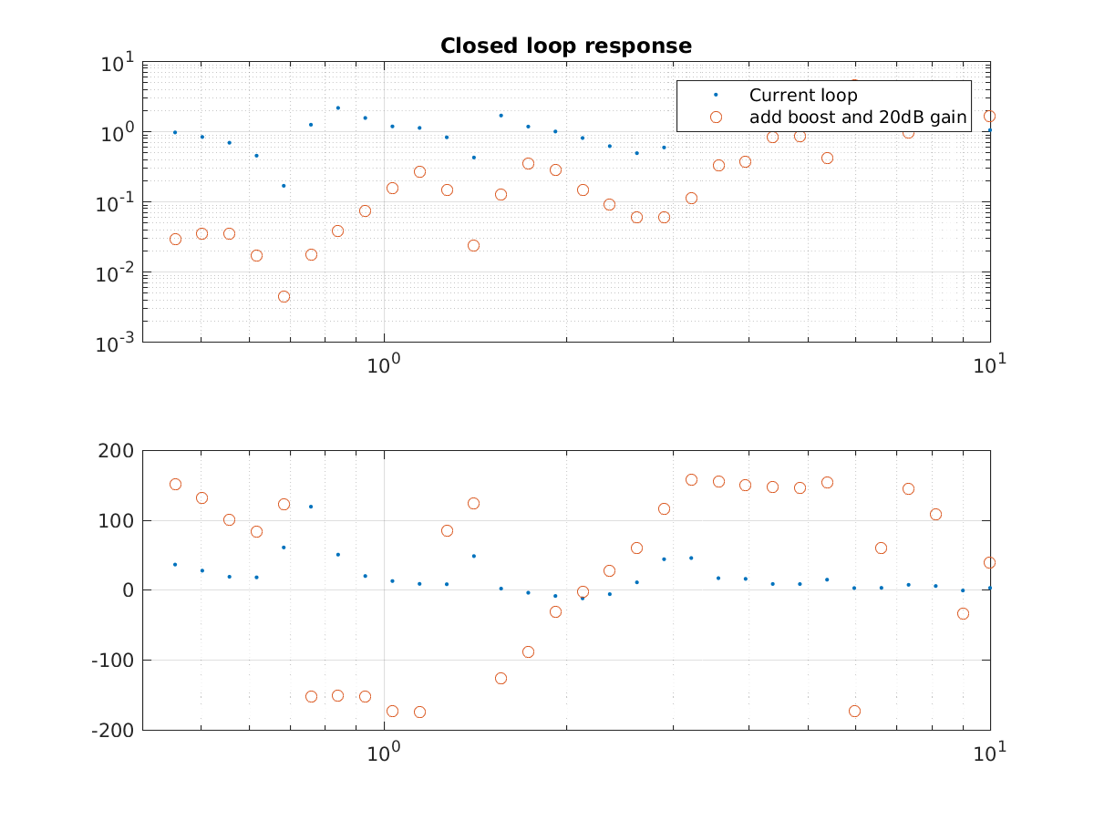
- Characterize all loops and optimize them for the best noise performance.
Well done!
Awesome!!!
Sweet!