We were thinking about whether we need to increase the bandwidth of the ASC MICH loops during the carm offset reduction sequence, so I measured ASC-MICH while sitting in DRMI (with ALS holding the arms off resonance). I also re-measured the loops after increasing the gain by a factor of 2. But, adding the factor of 2 increase into the guardian seems to be a bad idea, since several times this higher gain caused oscillations in the ASC MICH loop(s). So, it's commented out, although we could still consider adding more gain if we measure near the resonance around 0.5 Hz more carefully.
The plots attached all are the data points for which I had better than 0.6 coherence for both IN1/EXC and IN2/EXC. I plot measurements of MICH_P and MICH_Y for both the lowGain (original gain), and highGain (with the extra factor of 2).
Following are the consolidated bounce (vertical) and roll modes measured in-vacuum and in-air for the 4 QUAD suspensions.
| ITMX | B4 mode | VAC | 9.787 | AIR | 9.806 |
| R4 mode | alog 40098 | 13.902 | alog 39236 | 13.927 | |
| ITMY | B4 mode | VAC | 9.816 | AIR | 9.906 |
| R4 mode | alog 40098 | 13.898 | alog 38659 | 13.875 | |
| ETMY | B4 mode | VAC | 9.726 | AIR | 9.734 |
| R4 mode | alog 41488 | 13.788 | alog 40534 | 13.843 | |
| ETMX | B4 mode | VAC | 9.703 | AIR | 9.697 |
| R4 mode | alog 40098 | 13.757 | alog 42218 | 13.775 |
Jeff Kissel likes this. (Tagging DetChar and ISC.)
Today I updated the monitor filters for these new frequencies. Thanks Betsy for the nice table.
We have seen a couple of locklosses because of a rung up bounce mode when doing our low noise asc steps, changing the coil drivers, and transitioning to the low noise ESD all in rapid sucsession. The mode rings down very quickly, so we may just need to add a check on the monitor in some of these states and wait for the mode to ring down before we change the coil drivers.
I also added a check on the monitor that includes all the bounce modes in LOWNOISE_ASC, so that the guardian won't move on unless the monitor is below 2 (in arbitrary logarithmic units). The bounce mode wasn't rung up on our last lock, so we may still need to adjust the level of the check.
J. Kissel After Travis and I increased the PCAL line heights the other day (see LHO aLOG 43676) such that we might be able to see their amplitude in the current level of DELTAL_EXTERNAL sensitivity to get a preliminary and very rough check on the calibration. I've since gathered an ASD of the IFO's sensitivity compared with PCALY in a recent DC readout stretch (2018-08-28 06:31 UTC). As is rather obvious by the comparison, the calibration -- at least at 331.9 Hz -- is roughly a factor of (6.70948e-17 / 2.27309e-17 = 2.9517) ~~ 3 wrong. This isn't much of a surprise, since we're no where near the O2 level of laser power, but I just wanted to remind folks that we shouldn't yet trust the accuracy of the calibration. We can't yet resolve (at least in this lock stretch) the 36.7 Hz line, but we can resolve the 7.9 Hz line, which appears to be pretty accurate. Red curves are "live" (well, the recent Aug 28 06:31 UTC data), green curves are similarly "live" PCAL ASDs, the gold trace shows O2 levels of sensitivty -- where the PCAL lines were at the same frequency, but less amplitude, and within ~2% of the amplitude shown at 36.7 and 331.9 Hz.
J. Driggers, J. Kissel I was deceived by some red lights on the CDS overview posted to the wall thinking that there were DAQ problems with the H1 SUS ETMX last night while I was gathering data to characterize the highest bounce and roll modes (see LHO aLOG 43713). However, I'm reminded that it's an inconsequential flaw with this version of RCG that the ETMs are running (see LHO aLOG 43039). Long story short: I was looking at the CDS overview screens and found some filter files that were showing differences, indicating unloaded changes in a few filter banks. The list of front-end models with pending changes, and Jenne and my course of action taken is below. H1 LSC -- looks like a precision change of the sampling rate in the filters in MICH1 and SRCL1 banks, otherwise no changes to the actual function. The full filter file was loaded, and there are no longer differences. H1 SUS ITMX -- Small changes to the violin mode filter notching on the L2 LOCK stages; like the work of Sheila's finding out of the new yesterday. The filter file was loaded, and there are no longer differences. H1 ALS EY -- what looks to be substantial changes to the "ctrlHB" FM10 in the H1:ALS-Y_WFS_DOF_2_P filter bank (see attached screenshot for details). We know that Hang Yu has been working on this (see, for example, LHO aLOG 43516), but he's currently out of town, so we'll (for now) leave it unloaded and ask him about it.
After Hang checked, we have loaded the full foton file for ALSEY.
[Sheila, Haocun, Nutinsee, Terry]
Yesterday we also did a better OMC cavity scan with beams from squeezer.
Compared with last time, we used:
The results are shown in the attachment.
---> This tells us the propagation and loss from Faraday is ~7.34%. (SRM transmission = 32.34%)
In the Cavity:
Nice! A couple of quick questions about:
Where are these values measured? I imagine the input power was measured on SQZT6 (after the SQZ Faraday) and "Power in the cavity" actually means power incident on the OMC (like on AS_C). Is that correct? Is the alignment to the OMC that good because you engaged OMs alignment?
Yes,
input power was measured on SQZT6 (after the SQZ Faraday).
"Power in the cavity" means power incident on the OMC calculating from the scan, including 00 mode and higher modes.
OMC has good alignment because:
1. We are using ASC SERVO DC centering loops to align
2. We have seed power high enough
And there are some more info if you are interested in:
https://git.ligo.org/haocun.yu/lho_squeezing/wikis/Squeezing-Alignment
I'll energize IP1 in a few hours. We want to "sign-off" on IP1 asap so as to, then, be able to shut down our noisy pumps near HAM3.
Last night, the Hartmann team turned on the ring heaters on ITMY as well as ETMY. We set the ring heaters to half of a watt for 3 hours.
Based on the HWS ITMY prism trend data and gradient/contour plots (see attached), it appears that this Hartmann beam is well centered on ITMY. We could try to move a bit in pitch if needed.
The HWS ETMY did not acquire useful Hartmann beam information due to the following error: "ERROR: array must not contain infs or NaNs - State 3D". This error usually occurs when the Hartmann code obtains reference centroids while the green beam saturates the camera. It appears that the green beam was not shuttered during the measurement (see ETMY trend data attached) so this is mostly likely the case. Will try again tonight if commissioning permits.
As of 9:45 am local time, the LVEA is laser HAZARD.
Sheila, Georgia, Craig
We are leaving the IFO in the "LARGE_EQ" state because of the Mag 7 EQ in New Caledonia.
In the morning an initial alignment will be needed.
We've commented out the y arm states from the initial alignment guardian to avoid confusion . These states align IM4 + PR2 to the Yarm, which is only used when trying to align the input beam to the y arm for example for measuring the Y arm loss. During our normal initial alignment we want to set these to align the input beam to the x arm, not the y arm.
Georgia is starting a ring heater test at 5:00:30 UTC. She put 0.5 W to top and bottom on ETMY and ITMY. for 3 hours duration
Someone must have put the SEI config back in WINDY - when I came in a while ago to start initial alignment, everything was already ready, which was nice.
Changes are seen on both GigE cameras. Using the path length to the camera, and the pixel size, I calculated the angle change of the beam on IO GigE 2, and used that to calculate the change at 20m, the distance to MC2, and of course these are approximations, based on the current installation.
| change in pixels | change in mm @ MC2 | |
| IO GigE 2 X (IMC_IN) | 4.5 | 1.0 |
| IO GigE 2 Y (IMC_IN) | 9 | 2.0 |
Mark D., Tyler G., Chandra R., Kyle R.
Gerardo M. and I had previously found a leak on the newly installed chevron baffle spool-to-valve flange. Today I was able to vent IP1 and decouple the leaking flange and inspect it. At the site of the leak, there was evidence of damage to the spool's knife-edge. This "feature" is characteristic and typical of a flange fastener (stud in this case) having dragged across the knife edge during the flanging process when the two flanges are close but not in contact with each other. I can't say for certain but this likely could have been prevented had all of the studs been removed prior to bringing the two mating flanges together. Another abnormality was that the imprint of the knife-edge into the gasket material was very shallow in the region of the gasket corresponding to that which couldn't be brought "metal-to-metal". Gerardo will say more on this in his entry.
I consulted Chandra R. and we decided to attempt an in-situ "stoning" of the damaged knife edge. John W. had shown me this technique years ago and I have successfully repaired many "dinged" flanges using this approach. This entails finding a donor flange of the same size in the recycle bin and using it to pre-condition an abrasive stone such that arcs can be worn into it which match the knife-edge of the flange to be repaired. I then wet-stoned (using IPA) the damaged knife edge which removes the displaced material and restores the cross-sectional profile of the knife-edge (minus the displaced, now removed, material).
During the re-flanging following the repair attempt, I noticed that the new gasket fit loosely in the gate valve's flange. I tried a gasket from a different manufacturing batch and it too fit loosely. It looks like the tolerances are not standard in the valve's machining or are looser in the OD than typical at the very least. How loose? I didn't measure but would guess that the center of the gasket could be off as much as 0.040" from the valve's bore in any direction.
Anyway, I re-flanged, pumped down and helium leak tested the new joint. It looks good initially but I am leaving the leak detector connected and running overnight and will continue at the next available opportunity.
Completion of install effort from aLOG 43571
{Mark, Tyler, Gerardo, Kyle, Chandra}
Outstanding group effort today in vacuum department. Mark and Tyler installed chevron baffle + newly rebuilt IP6 ion pump (replaced a temporary blank on IP6 isolation gate valve); Kyle, Gerardo, Chandra leak checked. In summary we think the assembly is leak tight but there was some uncertainty because of leaky vent port on turbo plus multitude of KF joints. We saw a He signal in e-7 Torr-L/s range, but quickly discovered it was coming from the vent port on small turbo pump (vent port o-ring may be wrong size). We sprayed the vent port with instrument air and still saw a rise in He signal from background of 2e-9 Torr-L/s, into low e-8 Torr range, so we tried a few tests by toggling the right angle valve (RAV) on IP6. I sprayed the baffle flanges with the RAV closed (i.e. isolating the leak checker + external turbo from IP6 body) and we observed a rise in pressure. Similarly, while spraying the baffle flanges with valve closed while simultaneously spraying turbo area with instrument air, and then quickly opening the right angle valve to expose IP6 body to leak checker, there was no rise in He signal.
We finished late, so we will need to resume pumping on IP6 before we can turn its high volts on. It is currently pumped out and valved out. Leak checker was left on mezzanine. We will clean up our mess asap.
A few notes:
Appreciate everyone's patience today as we used a full maintenance day....and then some. :)
Soon we will have not four, but six ion pumps valved into corner station.
Did anyone track nipple and baffle serial number information?
Yes, ASSY-D1600431-004.
The code looks at H1:SQZ-VCXO_CONTROLS_DIFFFREQUENCY to determine whether or not it's locked and looks at 6MHz RF mon to determine whether or not it's ready to lock. I gave it +-5 Hz wiggle room for lock condition. frequency diff normally wiggles around +-2 Hz.
J. Kissel The new highest vertical (a.k.a "bounce") and roll mode frequencies for H1SUSETMX, measured at vacuum using driven excitations a.la. methods described in LHO aLOGs 41488 and 40098 are as follows: V4 9.703 +/- 0.005 Hz R4 13.757 +/- 0.005 Hz I'll update the uncertainty estimate later, once I can download the excited data I mention below. I've driven up the modes at two times (listed below) in order to gather an estimate of the Q, which I'll do again similarly to the aLOGs cited above once I get three. Exc Start Exc Stop Trial 1 Aug 28 2018 23:50 UTC Aug 29 2018 00:02:00 (stopped with 10 sec ramp) Trial 2 Aug 29 2018 01:05 UTC Aug 29 2018 01:15:00 (stopped suddenly but turning off TEST output) I'll want to get one more excitation time (plus an hour of ring-down time data). I'll look for a good target of opportunity in the next few days. It''s already obvious from watching the modes ring down in the sensor ASDs that the Qs will be in the 1000s, unlike ETMY which was unusually low (in the mid-100s) and split. The template for measuring the ASDs of sensors lives here: /ligo/home/jeffrey.kissel/2018-08-28/2018-08-28_H1SUSETMX_M0_V4R4_ModeSearch_BBinj.xml
[Jenne, Craig, PatrickG]
We have a new plotting / calculating routine that will plot a measured DTT transfer function, that has been measured via noise injection. As EvanH points out in alog 27518, data points with only modest coherence will be biased toward unity if you are just looking at the traditional DTT IN1/IN2 transfer function. So, now we have a command line tool that will extract the measurement data from DTT, and calculate the open loop gain from the cross spectral densities, and save a plot. Then, if you want to know what the loop shape would look like if you added some other filters, you can use the second tool to extract filter module info from python, apply those filters to the measured OLG, and plot the result.
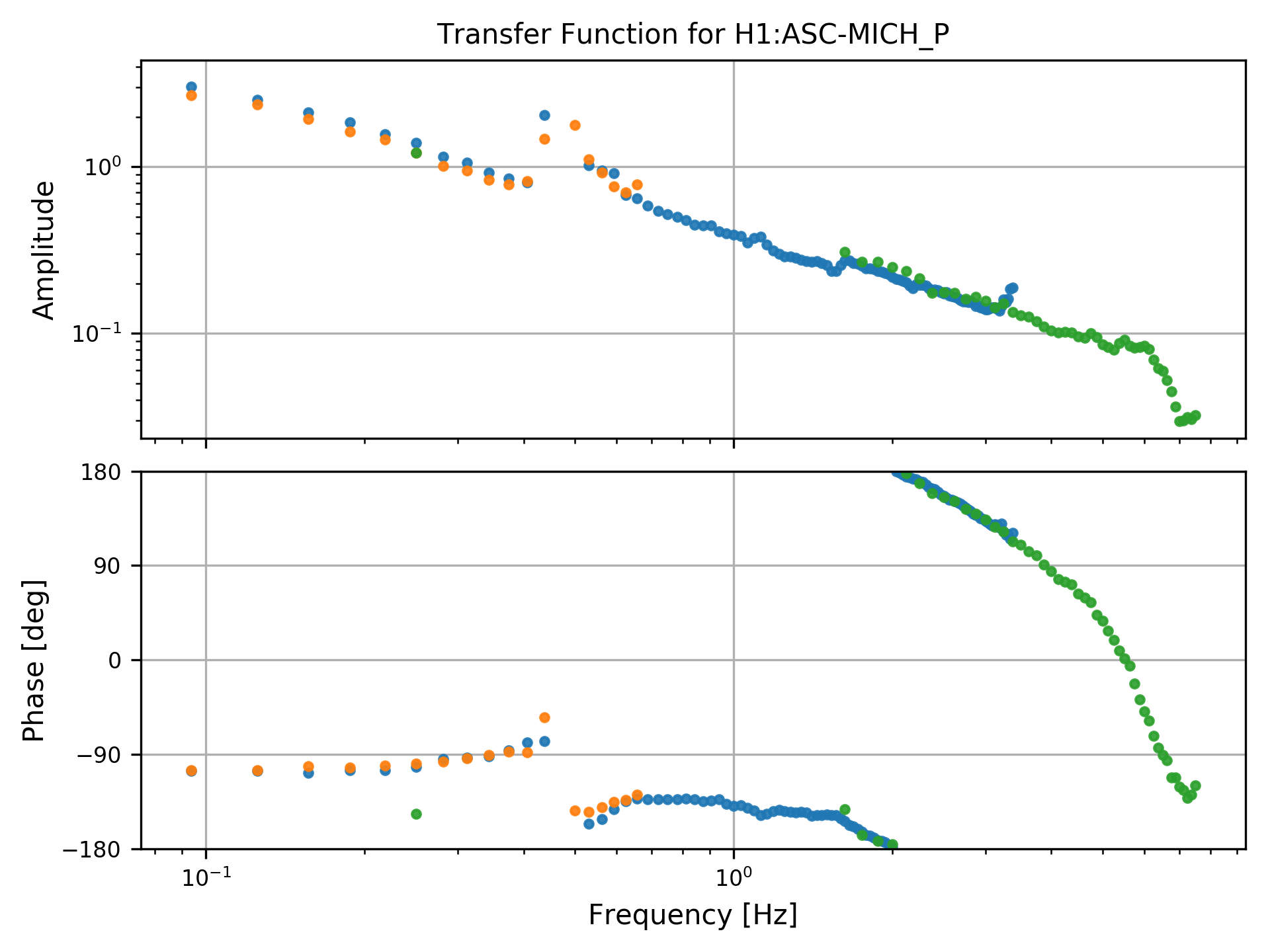
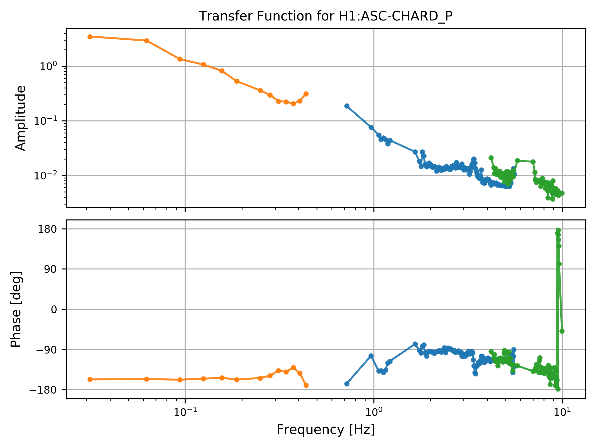
As is often the case with low gain loops (like our ASC right now), we can't push hard enough to excite with noise all of the frequencies that we are interested in. So, I have measured the CHARD loops with several bandpassed noise injections. The DTT extractor cannot get info about references, so each measurement must be saved in a separate .xml file. For example, I have 3 separate .xml files for the CHARD_P measurements that I took yesterday.
The output from the first plotter shows that CHARD_P, as it was yesterday, had very very low gain - see first attachment. Each color is the data from one of the frequency bands, for data points where the coherence between (IN1 and EXC) and (IN2 and EXC) are both greater than 0.5.
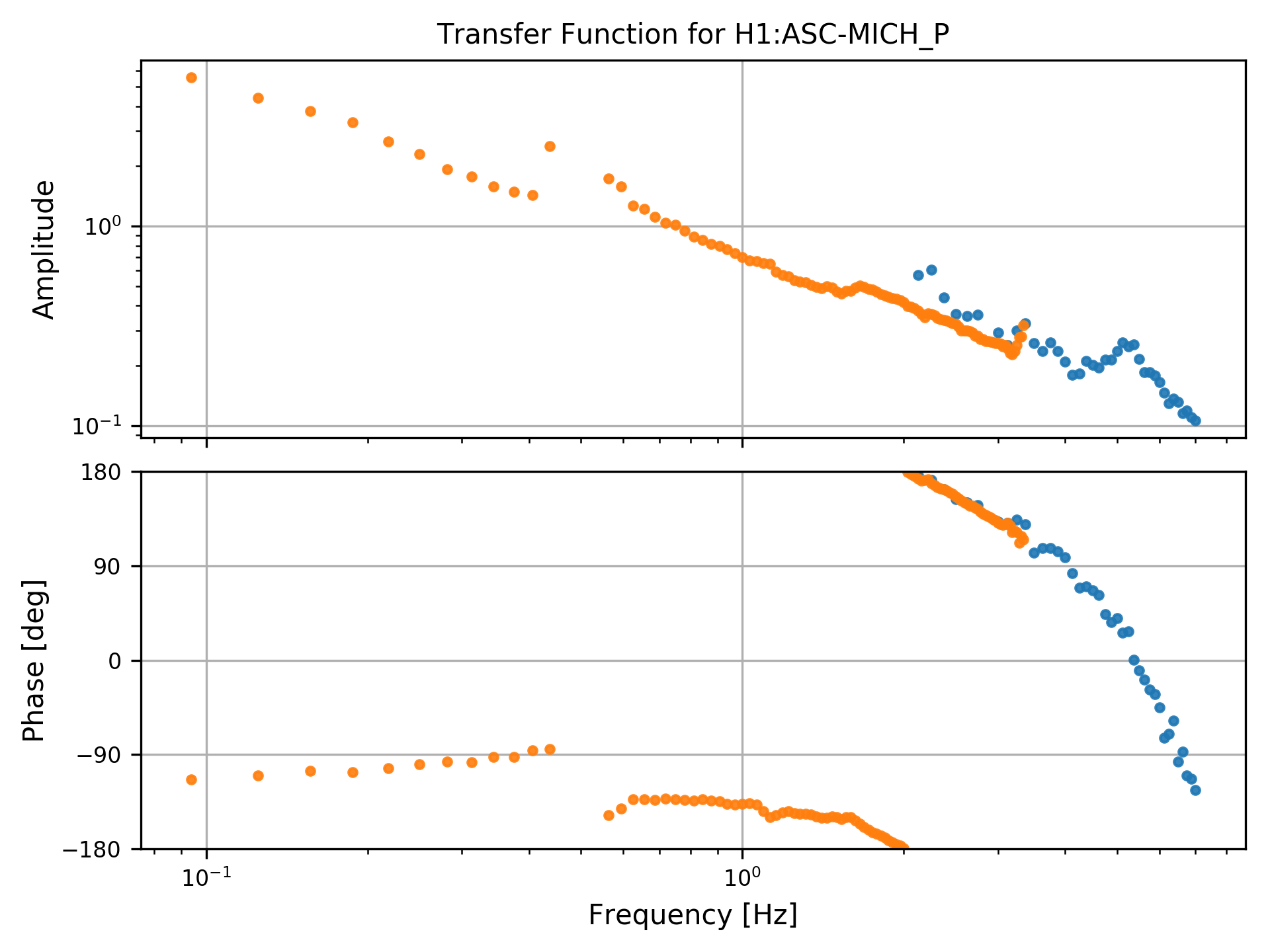
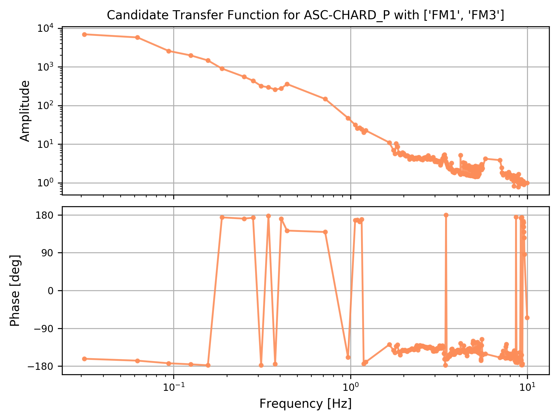
The output from the second - see second attachment - is the measured TF from above, with the indicated filters applied (here, FM1 and FM3, which is what guardian wants to have turned on for the power up). You can see that if we were to include both of these filters, we'd be unstable around 9 Hz.
Things that would be nice to add: a user-chosen coherence threshold, and the possibility of a user-defined gain value, and plotting of the loop suppression, so we can see if there is any expected gain peaking in the candidate OLG. Farther-future would even be to add error bars to the measurements, given the coherence. Also, a more generic location for the scripts.
For use right now (in a folder that contains your DTT .xml files):
>> /ligo/home/jenne.driggers/git/dtt_tools/bin/stitchTFs.py *.xml (In the case that you want all .xml files from this folder. Otherwise list them explicitly, space separated) This extracts the measurement data, saves the plot and the calculated OLG.
>> /ligo/home/jenne.driggers/git/dtt_tools_bin/plotFilters.py filename.h5 FM# FM# (The previous command saves the .h5 file, so pass that file name to this script. Then list the FMs that you want to add, space separated) (ex. filename.h5 FM1 FM3)
I made the above script work with swept sine TF measurements as well.
Keep in mind that you must source a python anaconda virtual env for this script to work: the version of python on the control room computers is ancient.
Proper instructions are here. Quick and dirty terminal commands copied below.
source /opt/rtcds/userapps/release/cds/h1/scripts/setup_anaconda
source activate python_for_dtt
Now you're in the environment and can run Jenne's commands above.
(Cheryl V, Gerardo M)
The yellow cover was removed, the viewport already had a viewport protector installed. The lexan cover was LOTOed, and the camera housing installed.
A WATEC camera was installed and pointed at the required component. Power was set temporarily and will be finalized soon, along with the camera signal to the control room.
Attached are images from the install: