Sheila, Terry, Haocun, Nutsinee
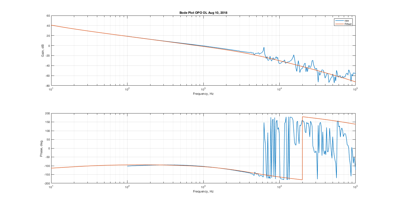
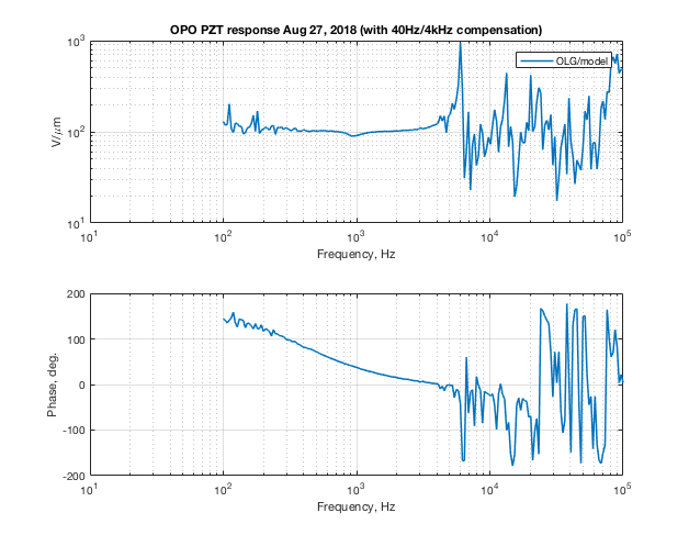
For the past few days we've had trouble with OPO locking stability and mystery offset in the error signal. Turned out we've been locking using the wrong compensation filter -- 40Hz/4kHz compensation on the common path instead of the 4/400 in the slow. Here's the OLG transfer function and the PZT response for each case (PZT calibration ~ 132V/um. I didn't do a quadratic fit but instead took the average of the two V/FSR. Good enough for now ) .
Wrong compensation filter
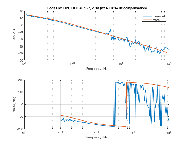

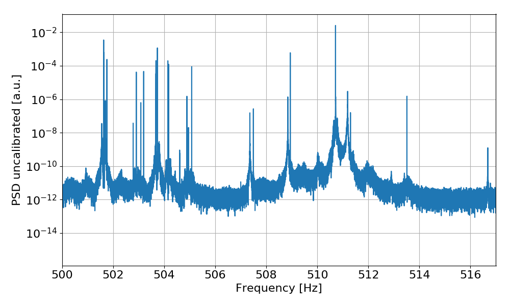
It's clear that we have very little phase margin here around the UGF. Gain peaking was visible around 2-3kHz on the PSD plot. Unable to engage the notch filter. End of story.
Correct compensation filter
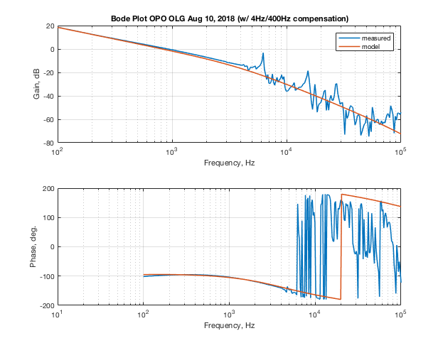
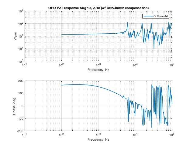

This is the configuration we should be operating on until the modified TTFSS board is ready.
How did we have the wrong configuration in the first place? Same old story. Beckhoff restart, things didn't come back right, and I was following the wrong note on the configuration. I will make sure Guardian turns on what needs to be turned on if I haven't already done so.
Offset issue -- to be revisited
We noticed that when operating at relatively high green power (18mW input to the coupler) OPO doesn't want to lock at the right place. The loop does what it's supposed to do by driving the error signal to zero but that's not where the green refl and trans were minimized and maximized. An offset at the common path had to be added after the loop catches lock.
I haven't tried very hard to replicate this issue after the wrong compensation filter was fixed. We have been fine as of the end of today operating at 15mW green power into the coupler.