Georgia and I created a violin damping guardian. The purpose of this guardian is to remove the parts of ISC_LOCK which used to set the violin damping gains and move it into a new guardian.
Right now the guardian is not managed by ISC_LOCK, although it should be once it has been tested more. Things should still be carefully monitored because we are still finding settings for the violin modes.
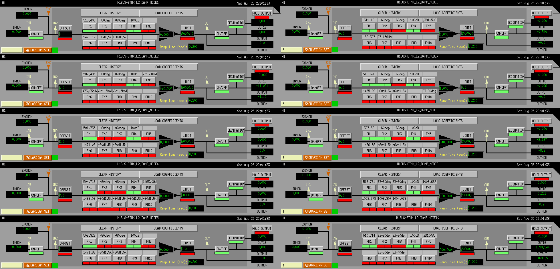
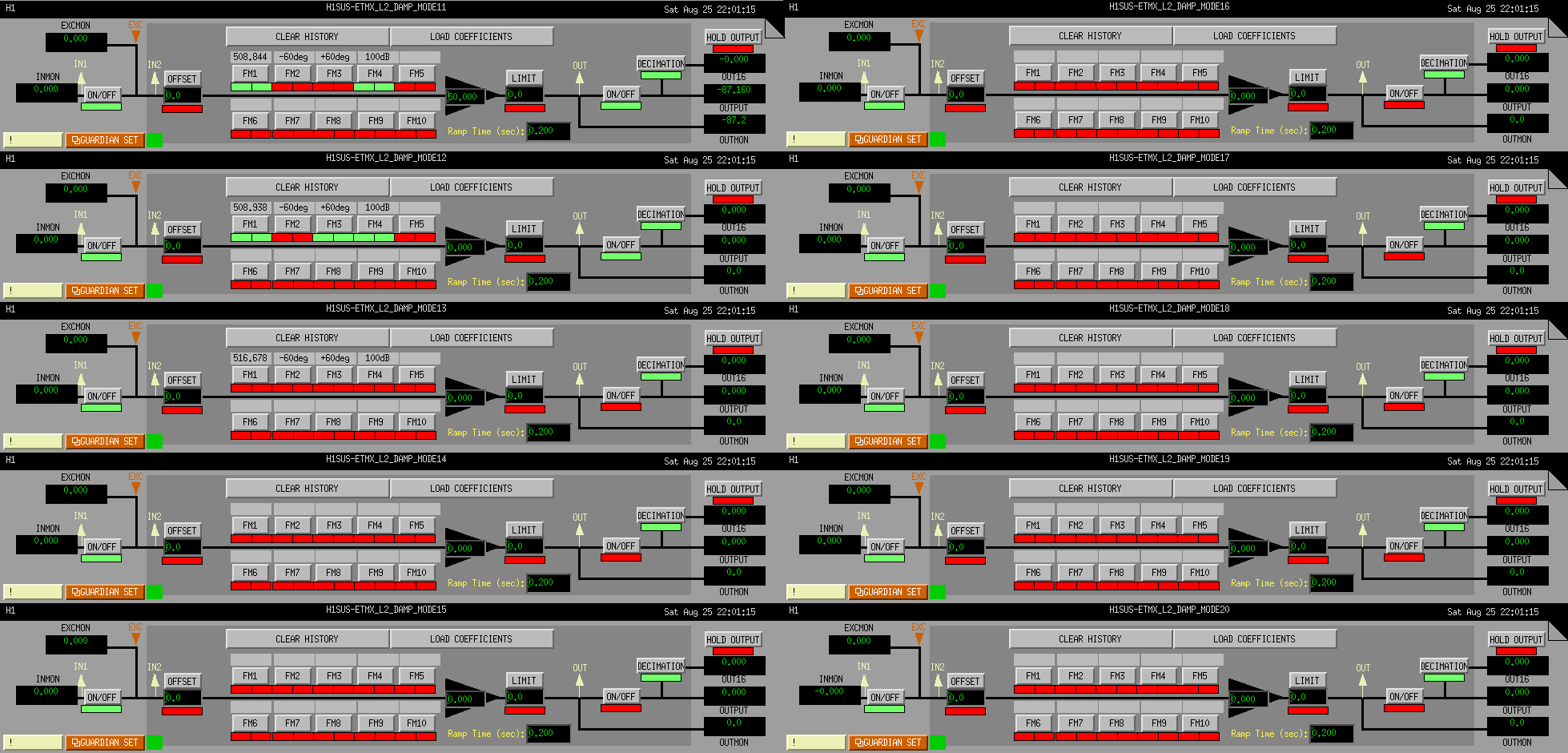
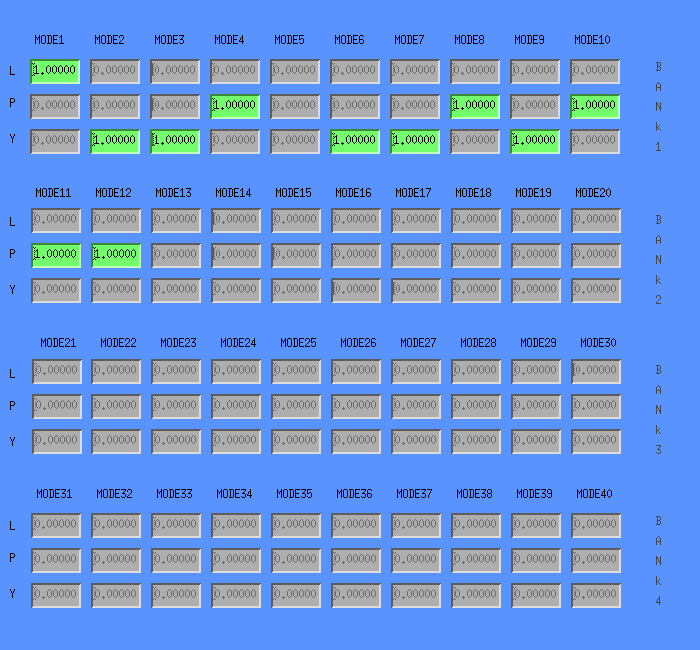
It has an idle state, and it has ENGAGE_DAMPING states for each test mass. This will only turn on the settings that are currently written in lscparams for each mode, regardless of how rung up or not the mode is. For now we have separate single optic states, because we don't yet trust all of our settings and want to watch what happens one optic at a time.
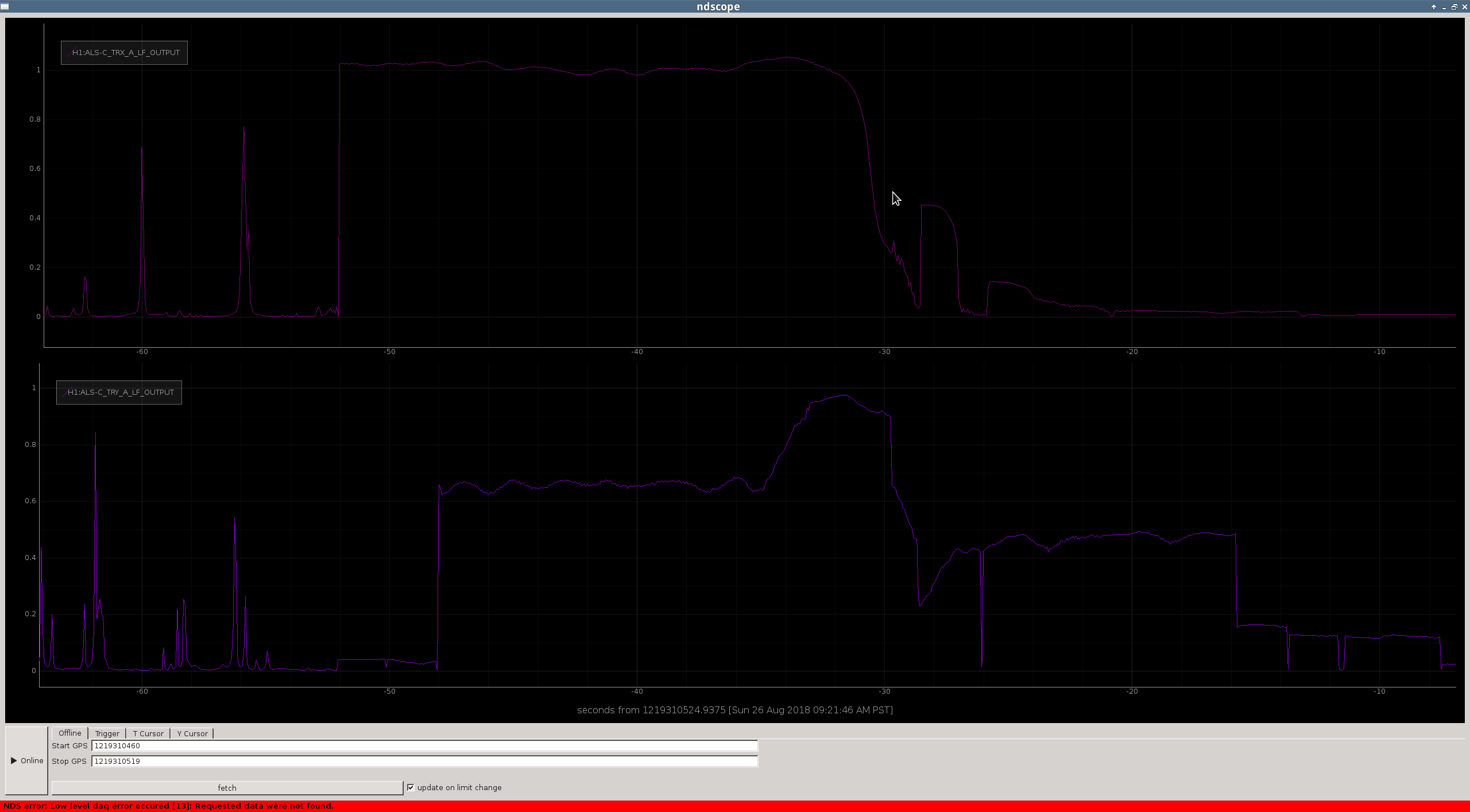
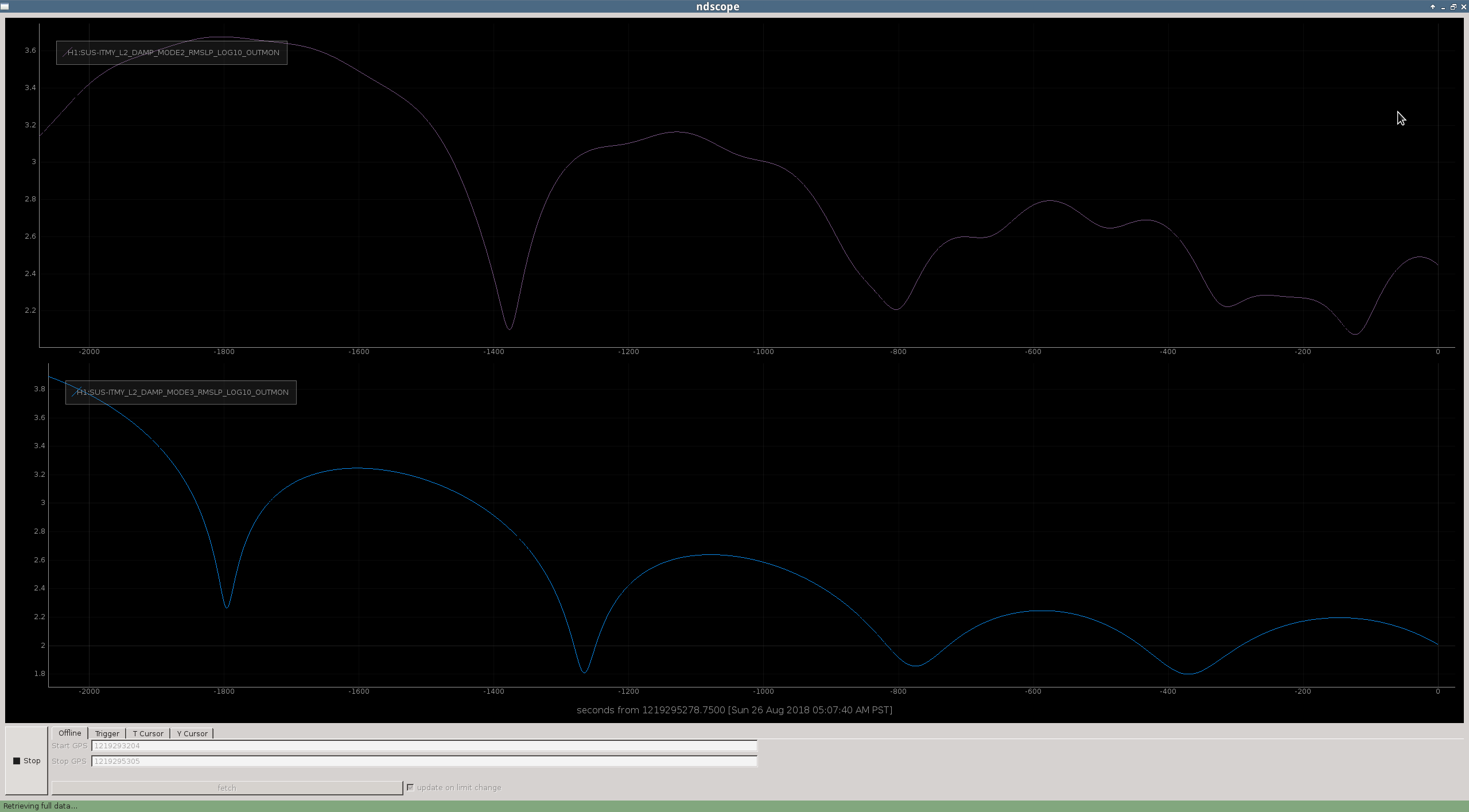
We also have states called ENGAGE_DAMPING_RF which check the level of the monitor filter and will only turn it on if the monitor filter is above the noise level of RF DARM. During O2 we used to always engage all the violin damping when DARM was locked on RF, but if the modes have been well damped in DC readout and not run up, then engaging the damping in this noisy state would ring them up. We started to populate the monitor filters with 8th order butterworth bandpasses that are 20 mHz wide, but this is not completed so we can't rely on these monitors yet.
Eventually we would also like this guardian to adjust the gains of individual modes based on how rung up they are.
Note that this is a different guardian from the VIOLIN_DAMPER guardian that Stefan wrote to find phase settings.