nutsinee.kijbunchoo@LIGO.ORG - posted 16:59, Friday 24 August 2018 - last comment - 16:59, Friday 24 August 2018(43601)
OPO green loss
It's lossy. 3% 0.16%
Final correction for MM subtraction. Now subtracted MM off the on resonance dip.
1.06% LOSS
[Edited after some input from Terry, Sheila and Daniel]
Calculation:
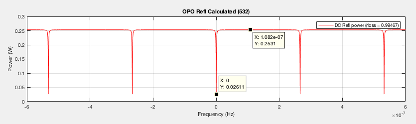
rloss = 0.99467
Amplitude loss t_L = sqrt(1-rloss) = 0.1031
Power loss L = 1-rloss^2= 0.0106
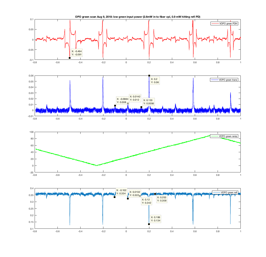
Here's what we have:
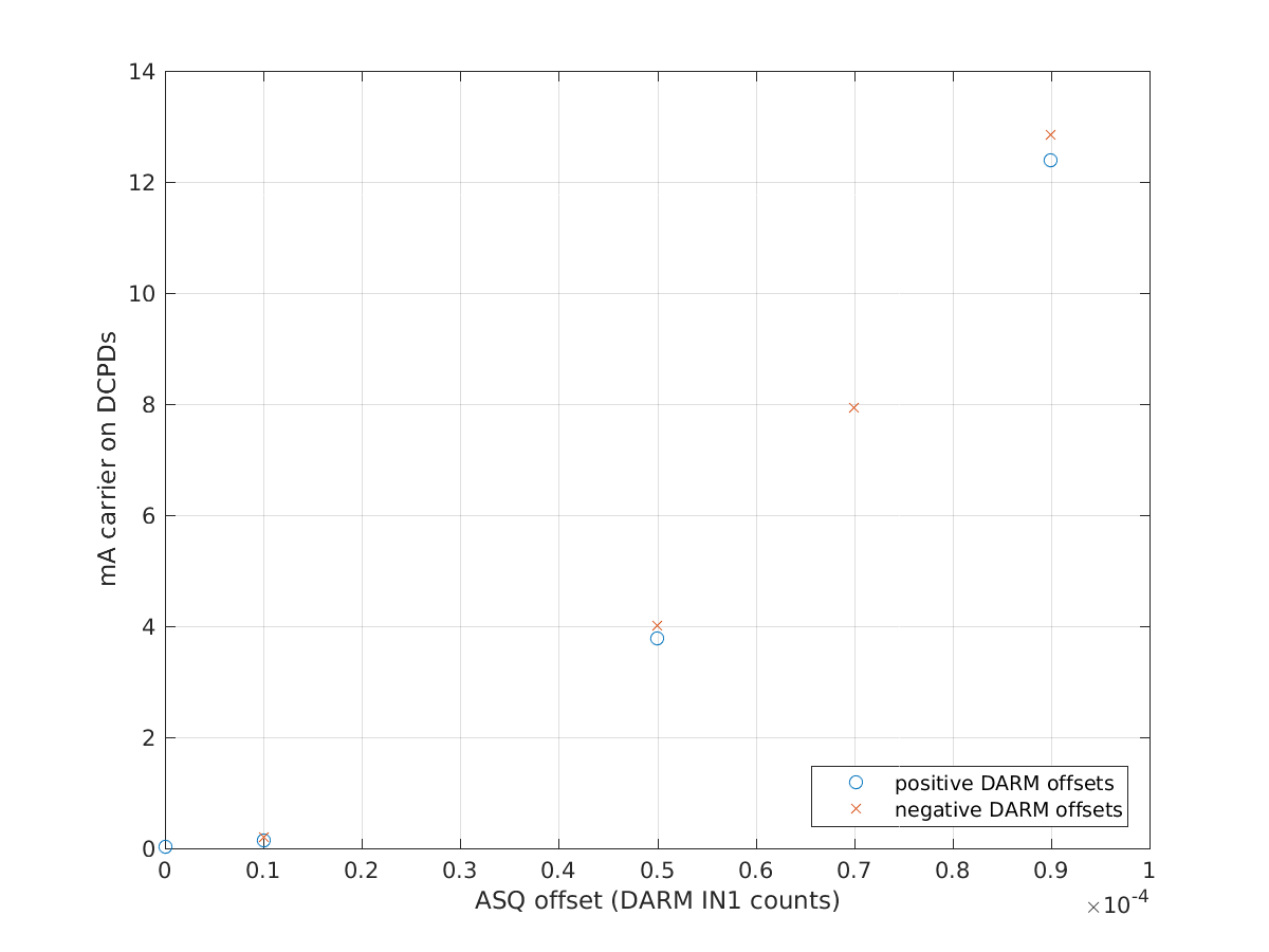
70% mode matching calculated from transmission (00 peak/all peaks = 0.06/0.0856 = .7)
Mode mismatch power = (V off resonance)*(1-.7) = 0.108 V
This yields our green dip to be 89.6% of the off-resonance power ( (0.36-0.108) - (0.134-0.108) ) / (0.36-0.108)
Images attached to this report
Non-image files attached to this report

Comments related to this report
Shouldn't the MM part be subtracted from both the incoming and the reflected light? What is the corresponding round-trip crystal loss?