Sheila, Stefan, Craig
- Very often when acquiring DRMI, we have 5-second baby-locks where DRMI is triggered and catches, then spontaneously drops lock. We have been triggering DRMI catches on POPAIR18 flashes above 20 for MICH and SRCL (PRCL is always triggered). Now we only trigger MICH straightaway, then after a 0.25 second delay, we "trigger" SRCL by kicking on SRCL1 FM1, which is now a +106 dB gain. We changed SRCL1 FM2 to be a -100 dB gain which is always on. (SRCL1 filter module pictured)
After making this change, we have still observed baby-locks, but have been consistently locking within about two minutes, never more than five minutes. This method avoids kicking SRM, which helps in general, but did not solve the baby-lock issue. We suspect something in DRMI_LOCKED state causes the baby-locklosses.
- ALS is unstable. Upon reaching LOCKING_ALS, when trying to lock DIFF we've been consistently losing the arms. Sheila lowered the QUIET threshold in LOCKING_ARMS_GREEN so the arms settle more before trying to lock ALS. After DRMI/IFO locklosses, we sometimes keep arms for a while, only to lose them a few minutes later.
- We stopped for the evening when the COMM PLL was not locking and we could not lock ALS. This whole COMM and DIFF PLL glitching/runaway frequency business is becoming urgent.
- ALS Y is still struggling to lock on the correct mode after lockloss. We reset the green YARM alignment using Kiwamu's QPD offset servo for zeroing green WFS. Unclear if this helped YARM acquistion, really doesn't seem like it.
- I tried to do the XARM as well but this nearly caused a lockloss twice. VERY unclear why that should be the case since by RESONANCE we should not be using green WFS to align our arms. A cursory check of the ALS DOFs confirmed they were all off (GAIN = 0) for both X and Y.
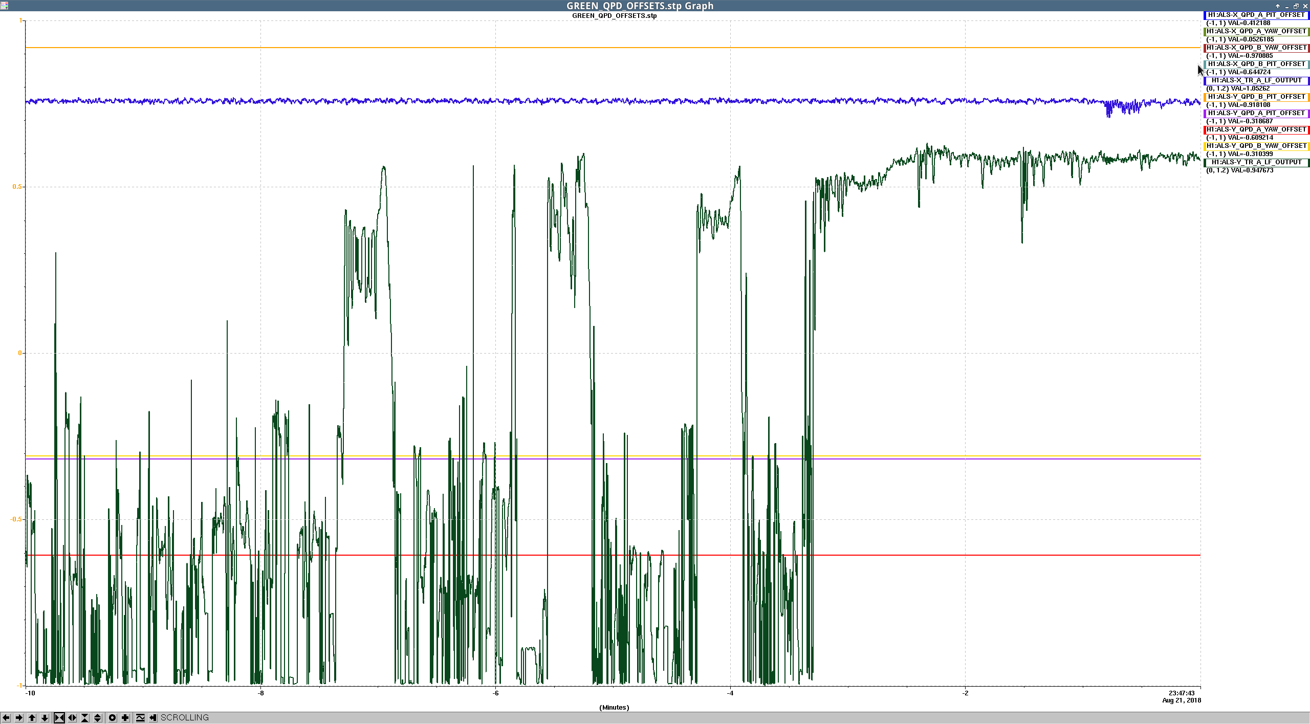
- New green QPD offsets in Pic 3, old ones in Pic 4.
- The ASC output matrix from MICH to the BS was inexplicably not set during PREP_DRMI_ASC twice. We had a similar problem with INP2 earlier. When we did execute the state, the log showed the ezca writing was really slow, could be an ezca issue. For now, we really have to pay attention to our ASC output matrix, because the control signals on the StripTool monitors are lies.
- Sheila walked ITMY in pitch today, and increased the recycling gain by 10% (from 28 to 31). We suspect we haven't completely finished the pitch walk, and need to walk yaw as well.
- Engaging the CHARD loops has proven difficult today. When closing CHARD, PRC2 tends to have a strong response, sometimes running away completely. When we closed all the corner ASC loops plus DHARD and CHARD, we achieved a recycling gain of 31.
- Stefan used his pr2spotmove.py script, with crazy results. POPAIR18 reached about 70 and POPAIR90 reached about 18 counts, a 80% increase. The recycling gain remained steady at about 30. We doubt this is real, but also don't have any good explanations. Maybe clipping on the POPAIR PD is causing and apparent RF power increase. It's possible it was real and clipping was just horrible on PR2, but this does not seem realistic, especially since the PR gain did not increase (PR gain is just calibrated POP_A_LF divided by IM4_TRANS). Picture 5 shows Stefan moving the spot on PR2 by adjusting PR3 pitch alignment, which soon after lead to a lockloss. We adjusted the WFS alignment back to when the POPAIR gains were normal.
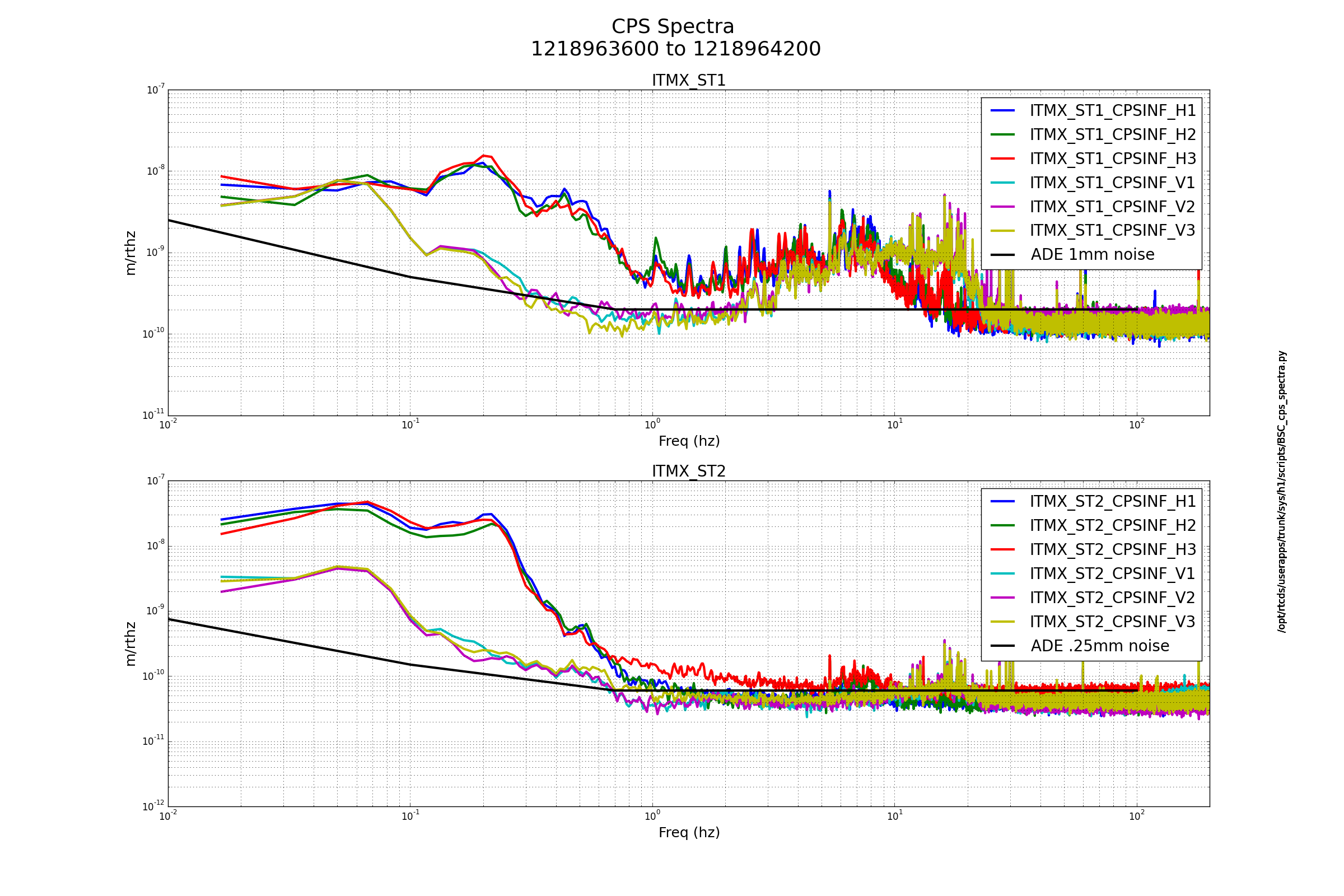
- At around 2:36:00 PDT there was a massive earthquake which tripped every single ISI watchdog we've got. Apparently it was a 6.3 located in Bandon, Oregon. The ground velocity is literally off the charts, reaching 30 um/s in the 0.03-0.1 Hz band. After five minutes of looking I found the REALLY BIG EARTHQUAKE button that's I've heard about and hit it, it changed every HAM state to ISI_DAMPED_HEPI_OFFLINE, hope that was correct.
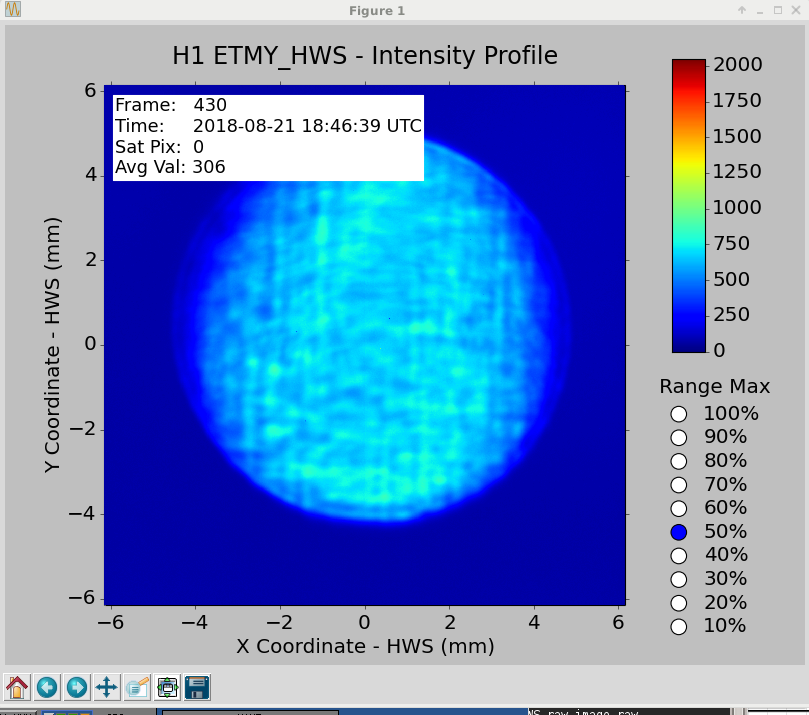
- I restarted the HWS code at around 2:26 PDT (GSP = 1218965247), and started the ring heater tests a little later, which said they should be done in an hour. I also started the HWS ITM PRISM PROBE dtt templates.


A few things to note:
1)We should try to avoid making requests in the run state without some sort of if statement to make sure we don't continuously make requests of managed guardian nodes.
2)When we see same state redirect in the gaurdian log, it means that we have requested it to run the state that is currently running, and the guardian responds to this by waiting one second, (REDIRECT waiting for worker completion) and after this starting the state over from the beginning. (This is usually not what we want, so we should use care not to request things that are already happening).
3) nodes[ISC_DRMI].arrived returns true when a guardian starts the requested state, not when it finishes it. There are some places in the guardian where we use this for states that are not just place holder states, and it seems the code is not doing what we expected in some places.