Displaying reports 45961-45980 of 88268.Go to page Start 2295 2296 2297 2298 2299 2300 2301 2302 2303 End
Reports until 12:29, Wednesday 22 August 2018
H1 SQZ (SQZ)
haocun.yu@LIGO.ORG - posted 12:29, Wednesday 22 August 2018 - last comment - 12:55, Wednesday 22 August 2018(43573)
OMC Scan with squeezer beam

[Sheila, Haocun, Nutinsee, Terry]

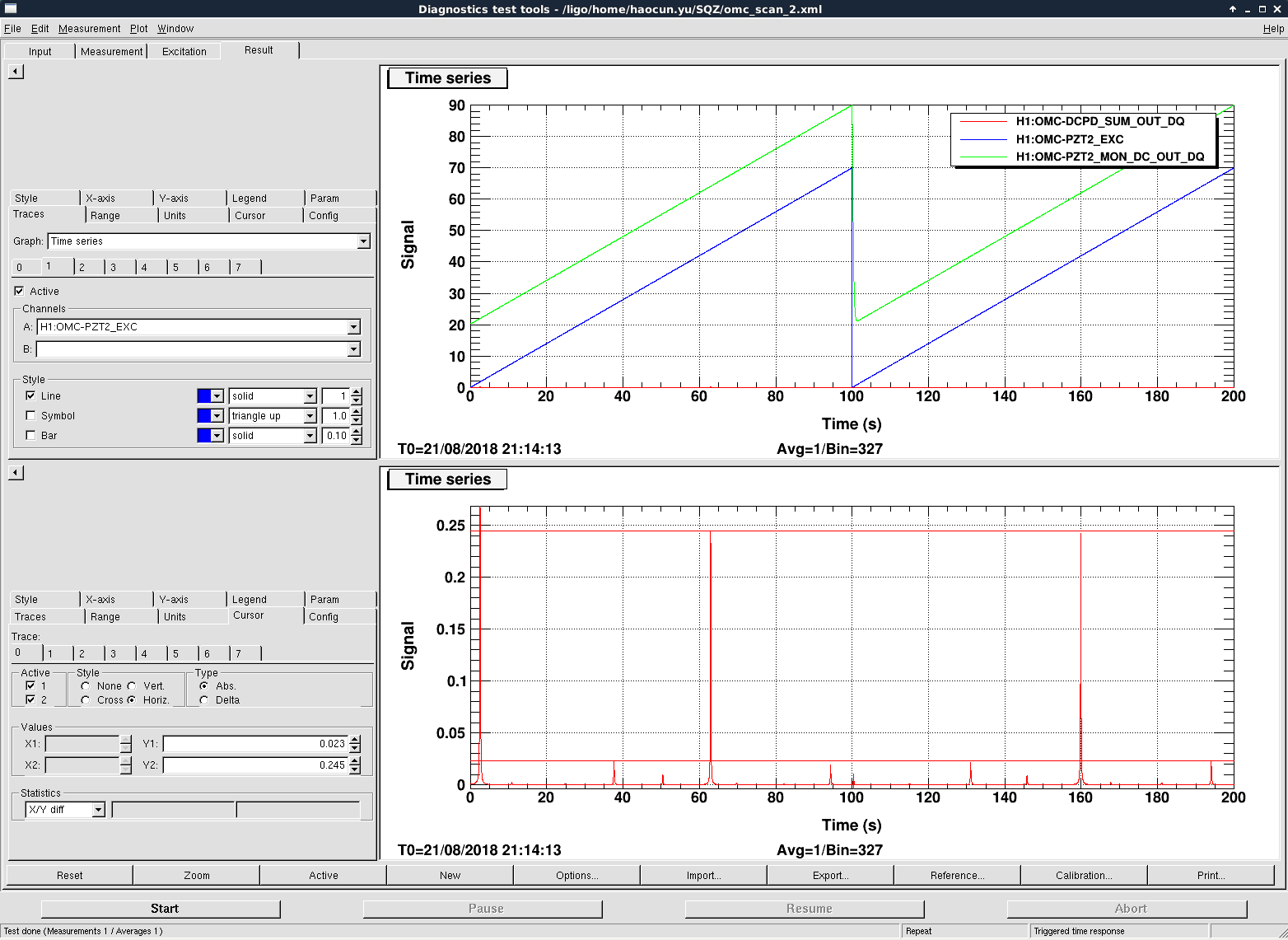
We managed to take a cavity scan of OMC with beams from squeezer.


We first used a full power SEED beam going in, but an OPO temperature not at exact dual resonance (because of the homodyne readouts fluctuations due to NLG).

This gave us an output even higher than the input..


Then we used CLF beam going in, which has a lower power, and at the peak of dual resonance.

This gave us stabler readouts on the homodyne, but the alignment were not as good as compared with using SEED.

We were also able to lock the OMC with CLF.

--> 18.7% loss (too much less than expected..?)


I am doing more calculations with the cavity scan data, and will add more follow-up details.

Next Tuesday we can work on centering loops using seed, from ZM1, ZM2 to AS_A/B.

Images attached to this report
Comments related to this report
lisa.barsotti@LIGO.ORG - 02:41, Wednesday 22 August 2018 (43581)SQZ

How do you get 19% with those numbers?

0.06/(0.13*(1-0.325)) = 0.68

This is more like 30% loss.

Do I misunderstand what you mean?

haocun.yu@LIGO.ORG - 12:55, Wednesday 22 August 2018 (43592)

Lisa, the OMC locking power should be 0.06mA on the DCPD, which means 0.07mW after calibration, but the 19% is probably under-estimated.


More numerical results (including corrections) from the cavity scan:


Using CLF:

From the plot:

Mode 00 01/10 20 higher
mA 0.0562 0.011 0.005 0.0021

Total: 0.0743mA --> 0.0885mW

Power input from Homodyne power is 0.123*1.13*(1-0.3234)=0.094mW  (factor 1.13: calibration factor of Homondynes which was forgot) --> Loss from propagation: 5.8%

00 mode: 75.6% --> Loss due to alignment and mode matching = 24.4%

10/01 mode: 14.8%

20 mode: 6.7%


Using SEED:

Mode 00 01/10 20 higher
mA 0.245 0.01 0.023 0.003

Total: 0.281mA --> 0.335mW (This is higher than the power input from Homodyne power, which is 0.37*1.13*(1-0.3234)=0.284mW)

00 mode: 87.2% --> Loss due to alignment and mode matching = 12.8%

10/01 mode: 3.5% (Alignment better than CLF)

20 mode: 8.2%


Conclusion:

Loss from Faraday and propagation: 6%;

Cavity loss due to alignment and mode matching is around 24.4%, in which mode matching accounts for ~7-8%.


We will try to take another measurement with higher stable power.

H1 SEI
hugh.radkins@LIGO.ORG - posted 08:26, Wednesday 22 August 2018 (43584)
LHO Recovery from the Big EQ

All the platforms were tripped after the 6.3 on the Oregon coast.  I used Jim's green Recover EQ button and it reset almost every platform.  HAM1, and a few of the BSCs needed to have their HEPI watchdogs untripped before proceeding and the BS remained in DAMPED rather than moving to ISOLATED_DAMPED.  Still the recovery was much easier than with the green button.  Thanks Jim!

H1 PSL (PSL)
peter.king@LIGO.ORG - posted 04:58, Wednesday 22 August 2018 (43583)
PSL table work
The light level on the PMC locking photodiode was reduced to ~100 mV when the PMC is unlocked.  In a prior
adjustment, the light level was ~250 mV and the gain slider was at -10 dB.  The current setting for the gain
slider is 8 dB.  With these settings the PMC servo has a UGF of ~1 kHz (as per the attached screen shot
from the SR785).

    The alignment of the reference cavity was improved.  One of the lenses in the beam path L12 was re-centered
onto the beam, and its mount was re-positioned so that it wasn't butting up against a mirror mount.  The
cavity visibility was measured to be ~80%.  In making the adjustments, the reference cavity transmission
signal increased from ~2.4 V to ~3.4 V with the ISS off.  This morning things seem to have relaxed so that
the signal is somewhat less (~2.6 V with the ISS on).

    The optic directing light to the reflection CCD camera was changed out to give more light to the
camera.  So the reflected spot on the quad display will look different.

    For reference's sake, it appears that L12 wants to move away from the reference cavity to improve the
mode matching further.


  Rick / Peter
Images attached to this report
H1 AOS (ISC)
craig.cahillane@LIGO.ORG - posted 02:48, Wednesday 22 August 2018 - last comment - 11:43, Wednesday 22 August 2018(43579)
Tonight's locking activities
Sheila, Stefan, Craig

- Very often when acquiring DRMI, we have 5-second baby-locks where DRMI is triggered and catches, then spontaneously drops lock.  We have been triggering DRMI catches on POPAIR18 flashes above 20 for MICH and SRCL (PRCL is always triggered).  Now we only trigger MICH straightaway, then after a 0.25 second delay, we "trigger" SRCL by kicking on SRCL1 FM1, which is now a +106 dB gain.  We changed SRCL1 FM2 to be a -100 dB gain which is always on.  (SRCL1 filter module pictured)
After making this change, we have still observed baby-locks, but have been consistently locking within about two minutes, never more than five minutes.  This method avoids kicking SRM, which helps in general, but did not solve the baby-lock issue.  We suspect something in DRMI_LOCKED state causes the baby-locklosses.

- ALS is unstable.  Upon reaching LOCKING_ALS, when trying to lock DIFF we've been consistently losing the arms.  Sheila lowered the QUIET threshold in LOCKING_ARMS_GREEN so the arms settle more before trying to lock ALS.  After DRMI/IFO locklosses, we sometimes keep arms for a while, only to lose them a few minutes later. 
- We stopped for the evening when the COMM PLL was not locking and we could not lock ALS.  This whole COMM and DIFF PLL glitching/runaway frequency business is becoming urgent.  

- ALS Y is still struggling to lock on the correct mode after lockloss.  We reset the green YARM alignment using Kiwamu's QPD offset servo for zeroing green WFS.  Unclear if this helped YARM acquistion, really doesn't seem like it.
- I tried to do the XARM as well but this nearly caused a lockloss twice.  VERY unclear why that should be the case since by RESONANCE we should not be using green WFS to align our arms.  A cursory check of the ALS DOFs confirmed they were all off (GAIN = 0) for both X and Y.
- New green QPD offsets in Pic 3, old ones in Pic 4.  

- The ASC output matrix from MICH to the BS was inexplicably not set during PREP_DRMI_ASC twice.  We had a similar problem with INP2 earlier.  When we did execute the state, the log showed the ezca writing was really slow, could be an ezca issue.  For now, we really have to pay attention to our ASC output matrix, because the control signals on the StripTool monitors are lies.

- Sheila walked ITMY in pitch today, and increased the recycling gain by 10% (from 28 to 31).  We suspect we haven't completely finished the pitch walk, and need to walk yaw as well.

- Engaging the CHARD loops has proven difficult today.  When closing CHARD, PRC2 tends to have a strong response, sometimes running away completely.  When we closed all the corner ASC loops plus DHARD and CHARD, we achieved a recycling gain of 31.

- Stefan used his pr2spotmove.py script, with crazy results.  POPAIR18 reached about 70 and POPAIR90 reached about 18 counts, a 80% increase.  The recycling gain remained steady at about 30.  We doubt this is real, but also don't have any good explanations.  Maybe clipping on the POPAIR PD is causing and apparent RF power increase.  It's possible it was real and clipping was just horrible on PR2, but this does not seem realistic, especially since the PR gain did not increase (PR gain is just calibrated POP_A_LF divided by IM4_TRANS).  Picture 5 shows Stefan moving the spot on PR2 by adjusting PR3 pitch alignment, which soon after lead to a lockloss.  We adjusted the WFS alignment back to when the POPAIR gains were normal.

- At around 2:36:00 PDT there was a massive earthquake which tripped every single ISI watchdog we've got.  Apparently it was a 6.3 located in Bandon, Oregon.  The ground velocity is literally off the charts, reaching 30 um/s in the 0.03-0.1 Hz band.  After five minutes of looking I found the REALLY BIG EARTHQUAKE button that's I've heard about and hit it, it changed every HAM state to ISI_DAMPED_HEPI_OFFLINE, hope that was correct.  

- I restarted the HWS code at around 2:26 PDT (GSP = 1218965247), and started the ring heater tests a little later, which said they should be done in an hour.  I also started the HWS ITM PRISM PROBE dtt templates.
Images attached to this report
Comments related to this report
jenne.driggers@LIGO.ORG - 10:03, Wednesday 22 August 2018 (43587)

[Hang, Gabriele, Jenne]

SRY of initial alignment was using that FM1, so we kicked SRM pretty hard several times until we re-read this alog.  HAM5 and all optics on it but SR3 tripped once, but SRM alone tripped several times. 

In the past, FM1 (then a +6 dB) was engaged after SRY caught lock.  So, the guardian's turning on this new +106dB gain obviously isn't what we want to do.  It seems like SRY is kind of fine with a factor 2 lower gain than it used to have (just leaving things with the acquisition gain), so we've just removed FM1 from engaging after the cavity is locked.  If we decide that SRY really does need that +6dB after the cavity locks and the integrator is on, we can adjust the input matrix gain.

gabriele.vajente@LIGO.ORG - 11:43, Wednesday 22 August 2018 (43591)

Here's a measurement of the MICH open loop transfer function in the MICH_DARK_LOCKED state, with the increased gain.

Images attached to this comment
H1 General
jameson.rollins@LIGO.ORG - posted 02:13, Wednesday 22 August 2018 - last comment - 11:42, Wednesday 22 August 2018(43580)
introducing ndscope

I have installed a prototype of a new dataviewer/pydv replacement that I'm currently calling "ndscope".

Features:

Planned features:

It should be available as "ndscope" in the path.  Please submit feature requests and bug reports directly to the ndscope issue tracker.

Images attached to this report
Comments related to this report
jameson.rollins@LIGO.ORG - 02:54, Wednesday 22 August 2018 (43582)

NOTE: dataviewer will be phased out in the near future, and ndscope is it's intended replacement.  Please keep that in mind while testing, and test extensively and provide feedback, so both you and ndscope are ready when dataviewer is decommissioned.

gabriele.vajente@LIGO.ORG - 11:42, Wednesday 22 August 2018 (43589)
H1 SEI
thomas.vo@LIGO.ORG - posted 23:32, Tuesday 21 August 2018 (43578)
strange motion of the optics today

Our optics are moving more than they should be with the ground motion we have right now.  It seems to be sudden glitches, which seem to be impacting mulitple suspensions. 

We can see that if we sit with just the green arms locked ITMY optical lever seems to have 0.5 urad glitches.  ETMY also shows some glitches.  The Y arm ALS control signal also shows these large glitches, and when we lock the interferometer these glitches also show up in IMC F..

Was there some configuration change today that might have caused this? 

It doesn't look like any of our ISI to suspension FF is engaged now. 

Images attached to this report
H1 ISC
stefan.ballmer@LIGO.ORG - posted 20:27, Tuesday 21 August 2018 (43575)
Green camera offsets updated
We had some recycling gain win, so here is a new green camera offset position:

H1:ALS-X_CAM_ITM_PIT_OFS  238.39   (was 241.3)
H1:ALS-X_CAM_ITM_YAW_OFS  311.57   (was 313)
H1:ALS-Y_CAM_ITM_PIT_OFS  320.12   (was 337)
H1:ALS-Y_CAM_ITM_YAW_OFS  304.33   (was 293.5)

With those numbers, the initial WFS turn-on move is a lot smaller too. More to come.
H1 ISC (ISC)
hang.yu@LIGO.ORG - posted 19:09, Tuesday 21 August 2018 (43574)
Why the AS72 is insensitive to longitudinal detuning?

Since people keep thinking about the possibility of phasing the AS72 WFS with a longitudinal drive of SRC or PRC, we think it is thus useful to provide a mathematical proof showing that 

the AS72 (both the SUM and each quadrant individually) will NOT see longitudinal perturbations to the linear order. 

Please see the attached note for the details of the proof. The only assumption we made in the derivation is that the carrier field is exactly on- or anti-resonance in the cavities. This should be a reasonable assumption as by design the carrier field should be resonant in PRC and anti-resonant in SRC. (In reality the alignment imperfections and contrast defect will inevitably detune the recycling cavities by a small amount, yet when a length drive shows up in AS72, it will show up in POP90 which behaves very much similar to AS72 SUM. The signal showing up there is actually a power fluctuation in the cavities quadratic in the length drive.) 

Non-image files attached to this report
H1 PSL
jason.oberling@LIGO.ORG - posted 17:44, Tuesday 21 August 2018 (43570)
PSL DBB Progress

J. Oberling, C. Vorvick, P. King

Quick Summary

The DBB is still not fully operational.  We have an alignment we think is OK, but are still unable to lock the DBB PMC.  There are a couple reasons for this (detailed below), which will be looked into the next time the DBB is worked on.

Details

Today we concentrated on resurrecting the 70W path of the DBB (the old beam path for the HPO) so we can take measurements of the 70W amplifier.  Peter took a beam propagation measurement for the 70W amplifier and performed a fit.  I then took his results and used JaMMT to find a mode matching solution (see 1st attachment; 0 is the front face of the 70W amplifier).  I then removed the existing DBB mode matching lenses and aligned the 70W beam into the DBB using the 2 irises along the input rail.  The mode matching lens holders were moved to their respective spots from the solution and the lenses installed.  Cheryl and I then worked on the beam alignment into the DBB PMC after lunch.  This took much back and forth and most of the afternoon, but we finally got an alignment that we think is OK.  Unfortunately the DBB PMC would not lock.  I think there are 2 reasons for this:

1) The DBB PMC has a CCD camera on one of its output ports that is used to watch the modes output while the cavity scans (aids in alignment).  We hooked a monitor up to this CCD camera and swept the cavity at 1Hz.  Watching the modes go by there were many different radial-looking modes that I don't remember being there last time I did this for the HPO in 2016.  Looking at an FSR scan on an oscilloscope, there were several peaks that I don't recognize either.  The usual 01 and 10 alignment peaks were there (which we worked to minimize), as well as the peaks that denote mode matching (which were large, which is why I think the lens positions need to be tweaked), but there were also a number of large peaks that I don't remember being there with the HPO.  Therefore the positions for the DBB mode matching lenses definitely need to be tweaked, but I also think (based on these other peaks I don't recognize) we need to work on improving the mode matching into the 70W amp.

2) Regardless of 1 above, we do not have enough power available to the DBB.  The maximum available right now is 63 mW (measured with a 3W power meter); the DBB needs at least 120 mW.  This is because of the change from the HPO to the 70W amplifier (while it needs to be updated to reflect the 70W amp installation, T0900610 can be used to see the locations of the mirrors I'm about to discuss).  The DBB uses a leakage beam from mirror M03, which has a transmission of 0.2%.  This leakage beam is then routed to the DBB via mirrors M12, M14, and M11 (in that order).  M12 and M14 both have small leakages (1% and 0.2% respectively), but M11 is a 50/50 beam splitter.  This is needed as the 35W FE beam also needs to make it into the DBB (it transmits through M11, while the 70W amp beam reflects off of M11).  So with 70W output from the amplifier, the leakage through mirror M03 is only 140mW.  The beam then loses 50% at M11, which does not leave enough light for the DBB.  In the short term, just so we can make measurements on the 70W amplifier, we can replace M11 with an HR mirror.  In the long run, however, we will have to replace mirror M03 to allow more light into the DBB.

Note: The DBB is experiencing the same problem we had in the lead up to O2; as soon as the button to open the DBB internal shutter is clicked, the DBB goes into INTERLOCK and will not function until reset (going to STANDBY clears the interlock).  We got around this today by moving the internal shutter, but this does need to be looked into.  Looking at past alogs after leaving the enclosure, it seems this was cured by unplugging the offending shutter and plugging it back in.  Next time the DBB gets worked on, this will be tried to see if it fixes the problem.

Steps to be taken next time the DBB is worked on:

Images attached to this report
LHO VE
kyle.ryan@LIGO.ORG - posted 16:59, Tuesday 21 August 2018 - last comment - 13:38, Friday 11 January 2019(43571)
IP1 installed today but has air leak

Mark D., Tyler G., Chris S., Gerardo M., Kyle R.  

Gerardo M. and I leak tested the new CFF joints after the installation was done this morning and measured a 1.7 x 10⁻⁸ torr*L/sec helium leak at the Gate valve to chevron baffle spool joint ->  This joint is visibly "gappy" for a portion of its periphery even after subsequent re-torques -> looks like the gasket may have been out-of-round -> I shut down the pumps and leak detector but left everything in place.  We will redo this joint during the Aug. 28th maintenance period. 

 NOTE -  We will need to soft-close GV5 and GV7 and, thus, interrupt the IFO during the Aug. 28th maintenance day.  We will also need the South Crane for a few hours and will need to coordinate with the people who will be on site  doing the annual crane inspection during that day. 

Comments related to this report
stephen.appert@LIGO.ORG - 15:43, Thursday 10 January 2019 (46348)

Leak resolved in aLOG 43718

Did anyone track the serial number of the nipple or the baffle?


gerardo.moreno@LIGO.ORG - 13:38, Friday 11 January 2019 (46369)VE
H1 TCS
thomas.shaffer@LIGO.ORG - posted 16:39, Tuesday 21 August 2018 - last comment - 18:04, Wednesday 22 August 2018(43564)
HWS EY Realigned with 50um Core Fiber

Danny V., Georgia M., TJ S.

Today we continued to touch up the alignment of the EY HWS path with the 50um core fiber that was installed last week. We ended up translating the BS2, the polarizer, and L3 because we seemed to have a good alignment to the irises, but it was not centered on these optics. There was some bright fringes seen on the outside of the beam that we cut out using the iris on the fiber launcher. After some minor tweaks to the alignment, we were able to get rid of much of the clipping on the sides that we saw previously, and we now have an almost round beam profile as seen on the HWS camera. (Attached a screenshot of the stream with a the plate off.)

Tonight we will run a ring heater test and post results tomorrow.

Images attached to this report
Comments related to this report
georgia.mansell@LIGO.ORG - 18:04, Wednesday 22 August 2018 (43604)
Some additional thoughts on HWS ETMY mode matching
 
Yesterday we also measured distances on the HWS path from the SLED to the polariser. They are roughly equal to that in Aidan’s mode matching mathematica notebook (T10001717).
 
According to that mode matching solution we should have a waist ~2.2 m after the fiber collimator (not technically a collimator but a lens after the fiber launcher, but I’ll call it a collimator anyway).
 
In reality (just looking at the beam size on the card) we see a waist roughly at the position of the diverging lens, 86 cm from the collimator. After the diverging lens the beam is diverging. We were not able to find a position of the 120mm lens where the beam continues to converge after the diverging lens.
 
L2, the distance from the fiber collimator to the diverging lens, is 4cm shorter on the table than in the mathematica notebook - 860 mm compared to 903 mm. I re-evaluated the waist size with the new distance, recreating plots on page 13 of the PDF, output 215 and 206, to see if this explained the difference in waist position. The notebook suggested the waist would move *further* from the fiber collimator, but not but very much. This is the opposite of what we see on the table.
 
Conclusion: if we need to be strict about mode matching we should measure take a beam scan to end-y to make sure we know the mode size coming out of the collimator, and look at this as a function of position of the collimator lens.
H1 DAQ
david.barker@LIGO.ORG - posted 16:34, Tuesday 21 August 2018 (43569)
h1nds1 (default NDS) crashed at 15:25 PDT

h1nds1 commenced a retransmission sequence starting at 15:24:27 which ultimately caused its demise at 15:25:16

Immediately preceding the first retransmission request were a rapid sequence of second trend requests, each about 7 minutes in duration (and some duplicated) for the channel H1:LSC-MCL_IN1_DQ

monit restarted h1nds1.

H1 SUS
yannick.lecoeuche@LIGO.ORG - posted 16:33, Tuesday 21 August 2018 - last comment - 20:28, Wednesday 22 August 2018(43568)
ETMX, ETMY Charge Measurements

We ran charge measurements this morning and afternoon for both ETM's. We see no unexpected changes in the ETM charge trends, so we don't believe that any charge was accumulated from the 8.2 magnitude earthquake on Saturday (August 18, 00:19 UTC).

Images attached to this report
Comments related to this report
georgia.mansell@LIGO.ORG - 20:28, Wednesday 22 August 2018 (43609)

In addition to the quadrant-by-quadrant measurements, I've been running some additional pitch-and-yaw four parameter measurements on ETMX, as described in alog-42572.

I've still got sign and order-of-magnitude problems, but here are the trends over the last 4 weeks.

Alpha and gamma are roughly consistent over time, which makes sense as they are associated with the usual actuation strength. beta-beta2 and Veff are trending away from zero consistent with space-charge polarisation. The latest beta+beta2 measurement is strange, but maybe more data is required to interpret this.

I've removed the yaw results for beta+beta2 (bias), and the pitch for beta+beta2(signal) due to poor coherence between the oplev and the drive.


The only comparable measurement I can take on ETMY is beta+beta2 (bias) which does not require a signal pitch/yaw/longitudinal drive (impossible with a broken quadrant).  ETMY's beta+beta2 (bias) is comparable to ETMX in pitch (4.5e-9 N/V), but an order of magnitude higher in yaw (3.1e-8 N/V), consistent with the higher response shown in the last plot of alog-43430.

Images attached to this comment
H1 ISC
gabriele.vajente@LIGO.ORG - posted 16:04, Tuesday 21 August 2018 (43565)
Trying to fix EY green PZT oscillation

[Patrick, Gabriele]

As reported in 43475, one of the PZT used to steer then ALS green beam into the Y arm (using the transmon QPDs) was oscillating at ~400Hz.

Today we went to EY, pulled the PZT driver, and checked the J9 jumpers which controls the bandwidth of the closed-loop PZT controlled (see also E1300870). The goal was to change them from the "full bandwidth" to the "half bandwidth" configuration.

Unfortunately, the jumpers were already in the half bandwidth configuration. Just to be sure, we moved both of them (X and Y) in the "full bandwidth" configuration. The 400 Hz oscillation in the QPD signals got worse.

We put everything back in the previous configuration. No change in the oscillation.

If we really think this oscillation is a big issue, here are some possible options:

  1. Contact the manufacturer and see how they suggest we modify/tune the closed loop controller
  2. Replace the thick 2" mirror with a lighter version, so that the resonance frequency will move up and hopefully out of the control band
  3. Add some "rubber" to damp the PZT resonance, so that the peak moves farther away from the unity gain
Images attached to this report
H1 General
travis.sadecki@LIGO.ORG - posted 16:03, Tuesday 21 August 2018 (43567)
Ops Day Shift Summary

TITLE: 08/21 Day Shift: 15:00-23:00 UTC (08:00-16:00 PST), all times posted in UTC
STATE of H1: Commissioning
INCOMING OPERATOR: None
SHIFT SUMMARY:  Full 8 hour maintenance day.  Ion pump install on input tube.  PSL work all day as well as various HWS and SQZ work.
LOG:  See attached txt file.


Non-image files attached to this report
H1 General
travis.sadecki@LIGO.ORG - posted 16:01, Tuesday 21 August 2018 (43566)
LVEA is laser HAZARD

Transitioned to laser HAZARD at 22:58 UTC (3:58 pm local).

H1 CDS
david.barker@LIGO.ORG - posted 14:29, Tuesday 21 August 2018 (43563)
Accessing HWS data from CDS workstations

Running the script hwsdata will automount the HWS Data directory and tell you its path. This is an automount, so it is not viewable on you workstatation unless you know its path beforehand.

H1 SQZ (SQZ)
nutsinee.kijbunchoo@LIGO.ORG - posted 12:16, Monday 20 August 2018 - last comment - 22:48, Tuesday 21 August 2018(43531)
CLF loop characterized and LO loop closed

Daniel, Terry, Haocun, Nutsinee

CLF

The furthest I can push the UGF was 6kHz. This gave us a gain margin of ~30deg. You can push to 8 but then gain margin drops to 10deg. 


LO

We closed the LO loop for the first time last Friday. Homodyne seemed to have a lot of RF gain. We were hitting it with no more than 200uW of optical power (CLF+LO combined) and it was already producing 6MHz harmonics straight out of the box. To get rid of the harmonics we are now hitting it with 157uW combined optical power (17uW CLF, 140uW LO). Homodyne RF characterization will be posted in a separate alog.


The UGF was around 2kHz with ~40deg phase margin. This cannot be pushed further because of the huge peak around 34kHz that's believed to be LO PZT. To see if current loop configuration is good enough we'll have to look at the noise spectrum out of the error signal when the HD is well balanced. Currently we seems to have a beam splitter that drifts over night in front of the HD.


Images attached to this report
Comments related to this report
nutsinee.kijbunchoo@LIGO.ORG - 22:48, Tuesday 21 August 2018 (43576)

Correction: "17uW CLF, 140uW LO" are power that went into EACH diode. To total power went to HD was actually 2x(140+13) uW

H1 PSL
travis.sadecki@LIGO.ORG - posted 08:26, Monday 20 August 2018 - last comment - 17:52, Tuesday 21 August 2018(43523)
PSL Weekly

Laser Status:
SysStat is good
Front End Power is -0.001465W (should be around 30 W)
HPO Output Power is 73.48W
Front End Watch is RED
HPO Watch is RED

PMC:
It has been locked 0 days, 4 hr 9 minutes (should be days/weeks)
Reflected power = 15.27Watts
Transmitted power = 41.38Watts
PowerSum = 56.64Watts.

FSS:
It has been locked for 0 days 11 hr and 29 min (should be days/weeks)
TPD[V] = 2.113V (min 0.9V)

ISS:
The diffracted power is around 3.2% (should be 3-5%)
Last saturation event was 1 days 18 hours and 52 minutes ago (should be days/weeks)

Possible Issues:
Front End Power is Low
LRA out of range, see SYSSTAT.adl


Comments related to this report
travis.sadecki@LIGO.ORG - 08:32, Monday 20 August 2018 (43524)

Someone from Team PSL should look into why the Front End Watch is red and the Front End Power is being reported as zero when it is actually not.

travis.sadecki@LIGO.ORG - 11:41, Monday 20 August 2018 (43532)

FRS ticket 11302 created.

edmond.merilh@LIGO.ORG - 16:08, Monday 20 August 2018 (43542)

The FE power was being reported by a power meter inside the HPO which is no longer included in the beam path. The new reading wil come from the pick-off that was installed at the output of the MOPA in conjunction with the 70W amplifier installation (channel for this TBA). I'm not sure about the FE watchdog showing RED. HPO WD needs to be changed to amplifier(or something) WD and LRA range is no longer of any use.  Also, I noticed that output power of the new amp is being reported as the HPO power (simple metadata change?). Everything else looks ok. I can look into this further and see about working on getting that MEDM screen/channels edited.

jason.oberling@LIGO.ORG - 17:52, Tuesday 21 August 2018 (43572)

The script used to create the above report needs to be updated (it's on my list to sit down with TJ and do this).  As Ed says, the FE power is being measured by a PD that is no longer in use; a new one has been installed and the channel exists (H1:PSL-AMP_PWR4 if I remember off the top of my head correctly).  The watchdog was red because it was OFF, so the report was functioning as intended here.  We also need some name changes for some of the items (HPO Output Power should be something like "70W Amp Output Power" and likewise for the watchdog), as well as an edit of the System Status check to match the changes for the 70W amplifier.

Displaying reports 45961-45980 of 88268.Go to page Start 2295 2296 2297 2298 2299 2300 2301 2302 2303 End