Displaying reports 46021-46040 of 88268.Go to page Start 2298 2299 2300 2301 2302 2303 2304 2305 2306 End
Reports until 21:46, Sunday 19 August 2018
H1 ISC (ISC, SUS)
hang.yu@LIGO.ORG - posted 21:46, Sunday 19 August 2018 (43521)
new SRM xover; stable CARM_TO_ANALOG transition

Stefan, Sheila, Hang

We realized that previously we kept losing locks at the CARM_TO_ANALOG stage could be explained by the following mechanism:

When we ramp up the CARM gain, it created glitches in the CARM loop. While the CARM loop could handle those glitches just fine, due to loop cross-coupling, the glitches would also show up in SRCL, and consequently saturate the SRM M1 stage.

To solve this issue, we modified the SRM M1/M3 L2L cross-over config.

The first approach was to reduce the SRM_M1_LOCK_L gain from -0.02 to -0.01. After this modification we successfully transitioned through the CARM_TO_ANALOG stage fine.

The second approach was to move the LP filter in the M1 stage from 20 Hz down to 12 Hz (in SRM_M1_LOCK_L, FM4), while maintaining the M1_LOCK_L gain to -0.02. This also reduced the high-freq component in the SRCL glitches. We were able to use guardian to transition through the CARM_TO_ANALOG stage twice with this approach without problems.

In the attached plots we also show the new SRM M1/M3 L2L TF in [m/ct] (with M1_LOCK_L gain -0.02, LP at 12 Hz), and the original M1/M3 L2L TF (M1_LOCK_L gain -0.02, LP at 20 Hz).

Images attached to this report
H1 AOS
daniel.vander-hyde@LIGO.ORG - posted 19:39, Sunday 19 August 2018 - last comment - 10:24, Monday 20 August 2018(43520)
HAM6 OMC TRANS cam not displaying image

Danny, Stefan, Hang

Went out to with Stefan realign the HAM6 OMC TRANS camera to better image the beam on the CCD. After Stefan left, Hang and I tried finishing up the job but the camera became unresponsive to medm. The camera started to run hot after a while so we believe the camera is suspect here and not the connection. To test this we carefully used the ISCT SHG TRANS connection to see if we could get any response from the HAM6 OMC TRANS cam. It still did not work. I reinstalled the camera back in its original place but I did not plug it back in (to avoid overheating). 

Comments related to this report
stefan.ballmer@LIGO.ORG - 10:24, Monday 20 August 2018 (43530)
- These cameras get pretty warm, so that part is normal.
- Video did no longer come up because the camera server on h1digivideo1 died. To restart:
   - ssh on to controls@h1digivideo1 (h1digivideo0 : CAM 01-10; h1digivideo1 : CAM 11-20; h1digivideo2 : CAM 21-30; etc)
   - the control commands can be found here: more /etc/monit/conf.d/h1digivideo1-cams 
   - in particular, to start CAM15: /etc/init.d/h1cam15 start
- The rest was some painful aligning of the hard-to-access camera inside the view port cover (with the lexan-shield in place).

Bottom line: the OMC_TRANS camera is operational again.
H1 CDS (DetChar)
robert.schofield@LIGO.ORG - posted 16:18, Sunday 19 August 2018 - last comment - 18:29, Monday 20 August 2018(43425)
Update on testing of new I/O chassis in H2 test stand

Summary: Previously we detected no contamination of ADC channels by fans or from magnetic fields from the on-board power supply, but saw drifting lines. After powering I/O and AA chassis with linear supplies, the drifting lines were much reduced. There are three remaining more subtle issues: 1) Coherence between blank ADC channels in a 0.94 Hz comb, produced by a flashing LED that indicates link state, 2) A 1.000 Hz comb in the duotone channel that is coherent with some blank ADC channels, 3) An occasional drifting line, that produces coherence between blank channels, suggesting a rouge oscillator in the AA or I/O chassis.

A previous log noted that the new I/O chassis has much lower contamination from fans and power supply magnetic fields than previously tested I/O chassis, but that there were drifting intermodulation peaks, possibly associated with the 24V power from a Sorenson switching power supply ( https://alog.ligo-wa.caltech.edu/aLOG/index.php?callRep=42907 ).

During the DetChar f2f, we powered the I/O chassis with a linear supply and found that the drifting peak features were mostly gone. I have since been looking into more subtle features in the blank channels of the I/O chassis. Figure 1 shows that the blank channel spectra are smoother (no evidence of drifting peaks) and the coherence between channels is significantly less than it was before replacement of the 24V switching supply (compare Figure 1 to https://alog.ligo-wa.caltech.edu/aLOG/uploads/42907_20180715170051_Figure4-CoherenceBetweenEmptyADCChannels.pdf ). But Figure 1 also shows that there are features associated with LED flashes.

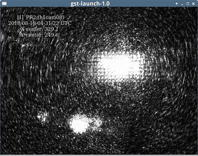
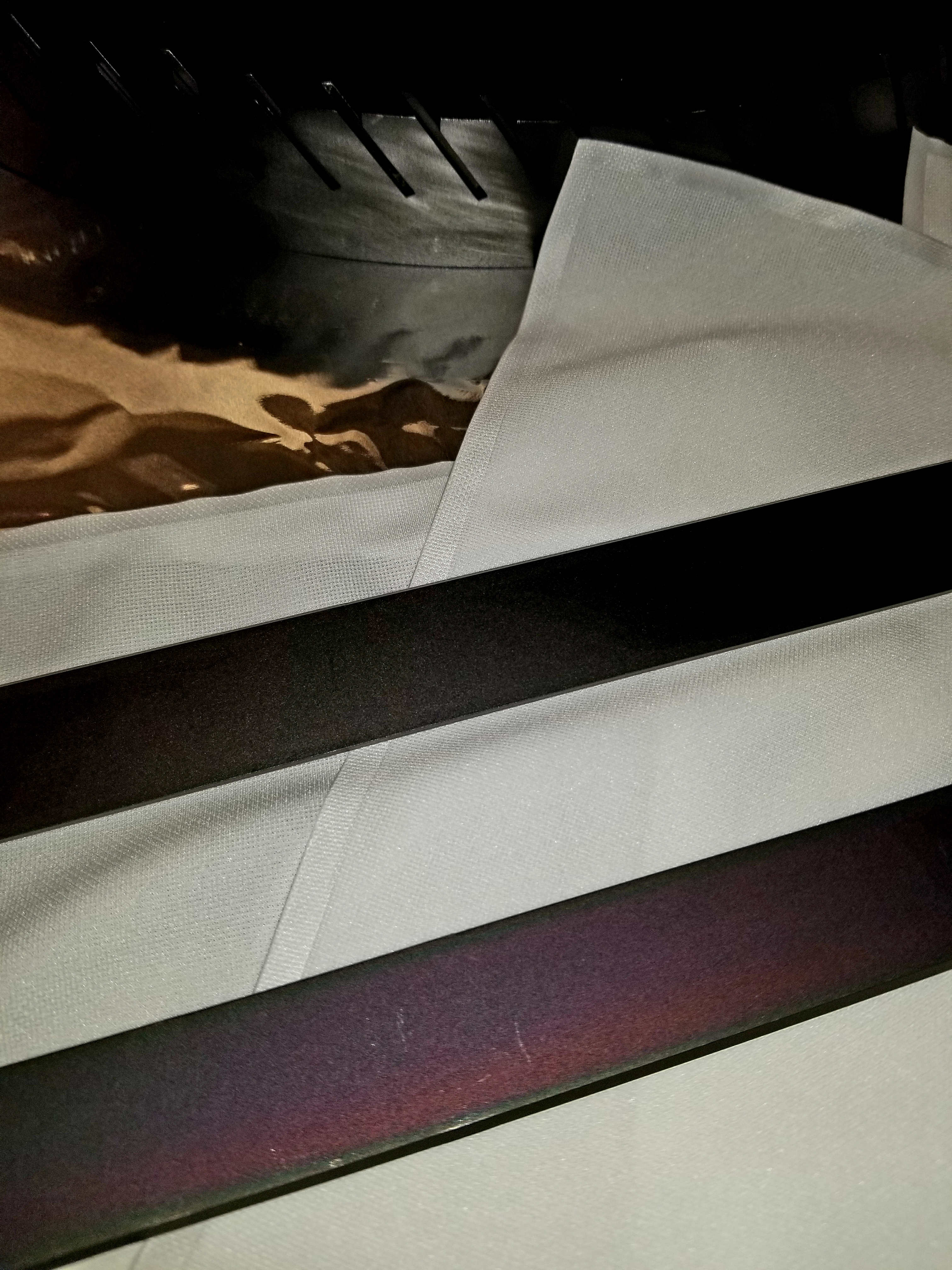
The odd harmonic series in the magnetometer signal of Figure 1 appears more strongly in the magnetometer signal when the magnetometer is near to flashing LEDs (link indicators) on the ADNACO-R1BP1B board (photos are also included in Figure 1). The coherence at LED frequencies between the magnetometer and the blank ADC channels reaches 0.1. The blank ADC channels are coherent with each other at the LED frequencies even when there is no magnetometer  connected, so the signal on the blank channels isn’t cross talk, and is probably associated with the periodic load on the power supply.

Dave B. notes that if the system were working as expected, the link LEDs should not be flashing.

In addition to the near-1 Hz comb, there was also a 1.000 Hz comb. Figure 2 shows that a 1.000 Hz peak, appears strongly (1 count) in ADC channel 31 (the duotone channel), and less strongly in other ADC channels (coherence reaching 0.01).  The LED flash peak is also apparent at 0.94 Hz in Figure 2, though all ADC channels are blank. Both peaks have an associated comb, odd harmonics for the LED peak and all harmonics for the 1 Hz peak.

The second page in Figure 2 shows that the duotone signals are at about 10^4 times the size of the 1 count peak at 1 Hz. The direct cross talk of the 960 and 961 Hz lines in, say, channel 15, visible in the power spectrum plot of the second page of Figure 2 at about 4e-2 counts, does not seem large enough to produce the 1 Hz comb in channel 15 through the same 1e-4-scale non-linear mechanism.  It may be that the 1 Hz comb on other channels has a different source or mechanism. We might be able to modify the duotone, such as by avoiding the zero cross region, to further study this. Since search groups had problems  with1.000 Hz and near-1.000 Hz combs in DARM during O2, I think it is important to understand/eliminate these peaks.

A final issue was that, although drifting peaks were reduced when the I/O and the AA chassis were placed on linear supplies, I found drifting peaks (Figure 3) in a couple of many spectra. I suppose that this peak could be associated with some rouge oscillator in the chassis.

Dave Barker, Sumeet Kulkarni, Philippe Nguyen, Robert Schofield


Non-image files attached to this report
Comments related to this report
keith.thorne@LIGO.ORG - 16:26, Sunday 19 August 2018 (43518)
Rolf Bork noted in our meeting last week that we could work with the vendor to get modified firmware to ensure that LEDs do not blink during normal operation. These indicators are related to the PCIe bus speed of the host computer.  We have found that changing the PCIe riser card from 3-slot to 4-slot on the original front-end hardware drops the PCIe bus speed from 5 GT/s to 2.5 GT/s.  In switching to long-distance PCIe RFM, we remove the need for the 4-slot riser cards.
david.barker@LIGO.ORG - 13:40, Monday 20 August 2018 (43536)

There was a misunderstanding, the on-board LEDs indeed should be flashing to indicate our ADC/DAC/BIO cards are PCIe-1 version cards with a reduced data transfer rate of 2.5GT/s.

keith.thorne@LIGO.ORG - 18:29, Monday 20 August 2018 (43545)
Another reason to go for custom firmware on these boards. I confirmed this behavior with the two long-distance I/O chassis at LLO for PEM MID.  The LEDs do blink on the slots with the Gen1 adapters (ADC, DIO)
H1 ISC (ISC)
hang.yu@LIGO.ORG - posted 13:11, Sunday 19 August 2018 - last comment - 16:46, Sunday 19 August 2018(43516)
new green WFS loops / Oscillation in the YARM DC centering loop

Jenne, Gabriele, Sheila, Hang

We modified the green WFS loops to make them higher bandwidth. See the first plot for the new OLTFs for XARM DOF1 (ctrling ETMX) P & Y.  Their gain were ~ x50 larger than the previous design, making the new loops have BWs of >~ 0.1 Hz. For DOF2 we also increased the loop gain by ~ x50. As the WFS loops being were much faster, the camera ones can also be faster as noticed by Stefan and TVo. The new gains are now put into the ALS guardian.

It turned out that previously we could not increase the BW of those loops because I foolishly forgot to low-pass the ctrl signal above the UGF. The high-freq noise then badly saturated the ETM PUM drivers. See the top panel of the second plot, the blue and cyan traces. We added a 4th order cheby1 lowpass at 1.5 Hz to each ctrl filter bank and now we can turn up the gains without major issues.

=======================================

Also notice that in the YARM green DC centering loops there exists a huge peak at ~ 350 Hz due to some instabilities in the PZT controller loops. Such signal can also be seen in the WFS signals as well (and dominated the previous ctrl signal rms before we put in the LP filters). It would be nice if someone could go to the Y end to fix it.

Images attached to this report
Comments related to this report
gabriele.vajente@LIGO.ORG - 16:46, Sunday 19 August 2018 (43519)

See 43477 for the PXT driver oscillation.

H1 SEI
sheila.dwyer@LIGO.ORG - posted 12:58, Sunday 19 August 2018 - last comment - 10:04, Monday 20 August 2018(43514)
Comparing Fiji EQ to Montana EQ July 6th 2017

Summary:

Last night's 8.2 in Fiji (at 0:49:00 UTC on August 19th 2018) is one of the larger EQ's we've had since the Montana EQ on July 6th 2017 6:35 UTC, on first glance it seems that the changes we made to protect our suspensions better after the Montana EQ were successful in reducing the amount of swinging that our quads did during this EQ. We will also want to make some charge measurements to make sure we didn't have any jumps in charge from hitting stops. 

Details:

Here is a comparison of ground velocity BLRMs: 

Frequency Montana (um/second) Fiji
30-100mHz 19 55
0.1-0.3 Hz 61 22
0.3 -1 Hz 20 24

After the Montana EQ we saw that our suspensions didn't return to the same positions for the same applied torque, and we had problems with charge on the optics. During the Montana EQ all of our ISI WD's tripped so that ISIs weren't damped, and all 4 quad suspensions also had their damping turned off by watchdogs.  Since that time we have made several changes to the watchdogs to better protect our suspensions:

In last night's EQ none of the quad suspensions tripped, while all the suspensions tripped and turned off top mass damping last July.   Looking at top mass pitch osem trends from last night, the peak to peak excursions were about a factor of 10 smaller than last July (300-600urad pp compared to 10mrad pp last July).  See the first attachment.  

For all the quad chambers, the ST1 trip was on the actuators and the stage 2 the first trip was on the CPSs.  Looking in more detail at ETMX (which seems similar to the others) The both ST1+ST2 watchdogs tripped within a second and did stay in state 2 (damping on, not checking for saturations) for 60 seconds before proceeded to state 3 as expected and described in T1700481.  The 60 second hold time was based on the Montana EQ (38919), and in this case it seems like 60 seconds was an adequate amount of time for the largest of the disturbances from the EQ to pass by.   Once both ST1+ ST2 watchdogs enter state3 where they begin to check for saturations again, the GS13s were still saturating and caused ST2 to go to state 4, full shutdown after about 7 seconds.  The shutdown of ST2 caused a kick to ST1, which saturated the L4Cs, and this caused the ST1 watchdogs to go to full shut down 2 seconds after ST2.  

We should also note that Stefan and T Vo pushed the VERY LARGE EQ button.  This button has been giving error messages lately, I don't know if it is really working. 

PS, I think I noticed a typo on the WD screen while looking at this, for ST1 where I think the monitor should be looking at  H1:ISI-ETMX_ST1_WD_L4C_SAT_COUNT it is looking at H1:ISI-ETMX_ST1_WD_MON_FIRSTTRIG

Images attached to this report
Comments related to this report
hugh.radkins@LIGO.ORG - 10:04, Monday 20 August 2018 (43529)

Thanks for looking at this Sheila but I think things are correct.  There are a few widgets on the WD screen in that area and they don't always stack up the same; so, when you middle mouse to get the channel name, you may not compare apples to apples.

The SAT_COUNT is the actual number of current saturations, the FirstTrig field you saw is compared bit wise to turn on the red light as appropriate.  I don't believe there is any problem in what is displayed but let me know if you see something of which I need be aware--thanks.

H1 SUS (ISC, SEI, SUS)
edgard.bonilla@LIGO.ORG - posted 20:47, Saturday 18 August 2018 (43513)
Scalar FF tested at ETMX w/ ISI ST2 RX/RY loops

Edgard, Hang, Jeff K., Brian.

I briefly gave a second chance to the ISIFF using length and pitch simultaneously, in a way similar to LHO:42875

The test was performed in ETMX, which has the RX/RY loops on. We observed no instability (see attachment 1, bottom left). This seems to suggest that the instability reported in LHO:42875 was indeed a result of the OSEM backreaction+ tilt horizontal coupling as we were suspecting.

The second attachment shows the power spectrum for L3P with and without the L-P simultaneous Feedforward. Two things to note:

        - The performance above 0.15 Hz is amazing, especially at the QUAD resonances. I almost don't believe these measurements, we'll investigate more into this later.

        - There is a lot of pitch motion being injected below 0.1Hz. This was completely expected, since I did not try to tune the bandpass carefully and only eyeballed the constant factors from the transfer function measurements.

__________________________________________________________________________

For the record, the values of the scalar FF I decided to eyeball the measurements described in LHO:43512 close to DC. Together with a recent M0 transfer function measurement found at:

/ligo/svncommon/SusSVN/sus/trunk/QUAD/H1/ETMX/ETMX/SAGM0/Results/2018-06-01_1602_H1SUSETMX_M0_DTTTF.mat

The estimate was made by using the DC levels of the TFs as described in (T1800301), by finding k= M0_L_2_M0_L/ST2_L_2_M0L; and l=M0_L_2_M0_P/ST2_P_2_M0P. I took care of calibrating into the right units too (cts/nm).

Images attached to this report
Non-image files attached to this report
H1 SUS (SEI, SUS)
edgard.bonilla@LIGO.ORG - posted 19:34, Saturday 18 August 2018 (43512)
ST2 to M0 transfer functions for full ISIFF in ITMX and ETMX

Edgard,

I took the ST2 X to M0 L and P transfer functions needed to do the L and P simultaneous feedforward (T1800301)

To do so I used the dtt template files located in the svn, with just enough modification to export the relevant quantities:    

/ligo/svncommon/SusSVN/sus/trunk/QUAD/H1/ITMX/Common/Data/2018-08-14_H1SUSITMX_M0_ISIFF_FilterDesign_ISIST2L_2_L3P.xml
/ligo/svncommon/SusSVN/sus/trunk/QUAD/H1/ETMX/Common/Data/2018-08-14_H1SUSETMX_M0_ISIFF_FilterDesign_ISIST2L_2_L3P.xml

The results for the transfer functions are shown in the first two attachments.

The third attachment was my attempt to make a measurement of M0P to M0 L,P, for ITMX immediately after that,  but there is this strange feature around the lowest resonance that drops my confidence on this measurement by a bit.

I suspect that, since I turned off the M0 damping filters, I rung up the longitudinal modes of the quad. And what I am seeing here, is a lot of motion at those frequencies unrelated to M0P drive.

In any case, it bothered me enough to stop there for those two suspensions.


Non-image files attached to this report
H1 ISC (ISC)
stefan.ballmer@LIGO.ORG - posted 17:52, Saturday 18 August 2018 (43511)
IFO locking
TVo, Stefan

We worked on getting the IFO locking again:
- As we went through the  initial alignment we noticed a few things:
  - ALS arm initial alignment: The camera feed-back gains are extremely low - we were able to increase the gain by x100 to make it converge faster. Also the ITMY green camera is now centered, and H1:ALS-X_CAM_ITM_PIT_OFS and  H1:ALS-X_CAM_ITM_YAW_OFS are updated to reflect the same alignment as before.
   - Even though not needed, we also tried the automatic INPUT_ALIGN_YARM states, but the ALIGN_IFO guardian always failed in PREP_INPUT_ALIGN_YARM. So we skipped it for today.
   - MICH_DARK: we just used MICH_DARK_LOCKED, and tweaked the BS by hand.
 - Then we started full locking and had no problem getting to RESONANCE. ITMY IR and AS cameras are now centered as well.
 - We then manually stepped through CARM_TO_ANALOG until line 1716, ALS-C_REFL_DC_BIAS','FM1','ON'.
 - Then our day was halted by an 8.2mag earthquake in Fiji.

 - Although we were not 100% sure what it does, we clicked the "Very Large Earthquake" button on the ISI SENSOR CONFIG screen. So we probably will have to set the ISI back to where we want it tomorrow morning.
H1 CDS (DAQ)
david.barker@LIGO.ORG - posted 10:37, Saturday 18 August 2018 (43509)
CDS model and DAQ restart report: Friday 17th August 2018

Now that we are locking H1, I'll restart the restart summary reports. All times in PDT.

model restarts logged for Fri 17/Aug/2018
2018_08_17 11:56 h1sqz
2018_08_17 11:59 h1dc0
2018_08_17 11:59 h1tw0
2018_08_17 12:01 h1broadcast0
2018_08_17 12:01 h1fw0
2018_08_17 12:01 h1fw1
2018_08_17 12:01 h1fw2
2018_08_17 12:01 h1nds0
2018_08_17 12:01 h1nds1
2018_08_17 12:01 h1tw1

Adding SQZ channels to DAQ.

H1 ISC (ISC)
craig.cahillane@LIGO.ORG - posted 23:59, Friday 17 August 2018 - last comment - 00:01, Saturday 18 August 2018(43505)
Locking tonight
Georgia, Craig

- Lost lock twice in CARM_TO_ANALOG, once while trying to increase the Sum node REFLAIR9I gain to 23 dB, and once when trying to engage the CARM Servo compensation boost.  Managed to get through by slowing the increase of the REFLAIR9I gain, and increasing the final gain on sum node to 28 dB.  Made changes to guardian, now able to successfully request PREP_ASC_FOR_FULL_IFO (made it through directly twice).

- Increased DARM offset to 9e-5.  Had to do this to lock the OMC to be over 11 mA on the DCPDs.  Still not very robust, our last lockloss came while we were trying to relock the OMC by hand after it had locked on a 45 MHz sideband.

- Tried to get to DC READOUT and failed once.  We measured the TF between LSC-OMC_DC_OUT and ASC-AS_A_RF45_Q_SUM_OUT and got a ratio of 3.36e7 at 100 Hz with 150 degrees of phase.  The input matrix element for ASAIR_A_RF45_Q to DARM was -1e-6, so we put 33.6 into the OMC DC matrix element and tried to make the transition.  It is extremely unclear what ASAIR_A_RF45_Q actually is.  Georgia and I looked in the matlab models and in h1lsc we found that LSC-AS_A_RF45_I/Q_SUM goes to ASAIR_A_RF45_I/Q.  Not clear yet if ASC-AS_A_RF45_Q_SUM_OUT is the same as LSC-AS_A_RF45_Q_SUM.

- ALS_DIFF is intermittently noisy when we lock ALS.  We did a quick test where we locked only ALS_DIFF while ALS_COMM floated about.  We discovered that DARM becomes more quiet when the COMM PLL unlocked.  Plot 1 shows a striptool where DARM is green and COMM PLL control voltage is blue.  It's unclear to us right now why the COMM PLL should have any effect on DIFF noise.  

- ALS_YARM is struggling to reacquire upon locklosses.  Georgia keeps restoring ETMY and TMSY to their OSEM witnesses in order to lock.

- PRM yaw is bad when locking DRMI.

- PR2 has bad scattering.  Pic below.
Images attached to this report
Comments related to this report
georgia.mansell@LIGO.ORG - 00:01, Saturday 18 August 2018 (43506)

Evidence of how well the IFO was behaving for us tonight: a 11 minute recovery time from a lockloss back to the resonance ISC_LOCK state.

Images attached to this comment
H1 AOS
craig.cahillane@LIGO.ORG - posted 20:39, Friday 17 August 2018 - last comment - 11:51, Saturday 18 August 2018(43504)
More FSS
Posting Peter's FSS measurements from today with common gain changes.  This is in conjunction with the fast gain changes from yesterday.

Impressions
We are able to reach 500 kHz UGF with Common Gain = 26 dB, getting closer to the top of the phase bubble.
If we turn down the common gain too much, the EOM and PZT paths start to peak at 100 kHz.

I also attached the PC and Fast monitors during the time of Peter's measurements (5:00-7:30am PDT).  If you look closely you can see when Peter adjusts the common gain on the PC monitor, which according to the schematic is 1/10 of the actual PC output.  It seems that  there was no real difference in the PC monitor between the times of high and low gain.

Sheila and I looked at the PC monitor at a time when the IMC gain was increased such that the UGF was 100 kHz, and there was really no difference from a time during lower gain.

It doesn't seem like EOM saturations are causing locklosses in the IMC.
Images attached to this report
Comments related to this report
sheila.dwyer@LIGO.ORG - 11:51, Saturday 18 August 2018 (43510)

I thought these gain changes were only temporary tests and are now restored to their old values.  Is that correct?

LHO VE (VE)
gerardo.moreno@LIGO.ORG - posted 19:37, Friday 17 August 2018 - last comment - 12:22, Thursday 23 August 2018(43502)
IP1 Chevron Baffle Assembly Update

Blades were selected for the baffle, best ones, but discovered that the hole on blades needs to be cleaned up (deburr) to be able to complete the assembly.  Tools are in the oven, need them to be "class B".


Images attached to this report
Comments related to this report
gerardo.moreno@LIGO.ORG - 19:41, Friday 17 August 2018 (43503)VE

The entire batch of blades produced 3 that have coating issues, one is coated about 10%, a second one about 70% and a third one has reddish hue all over it.

Images attached to this comment
stephen.appert@LIGO.ORG - 12:17, Thursday 23 August 2018 (43620)

These louvers should be rejected and the disposition should be to send for rework by the vendor. Thanks for the log of these coating issues!

stephen.appert@LIGO.ORG - 12:22, Thursday 23 August 2018 (43621)

@Gerardo: Was the prior deburring of the fixturing hole insufficient, or did it appear that no deburring had taken place?

H1 TCS (TCS)
georgia.mansell@LIGO.ORG - posted 13:14, Friday 17 August 2018 - last comment - 13:27, Sunday 19 August 2018(43492)
CO2X cenetering on ITMX

Danny TVo Georgia

This morning we pico'd the top periscope mirror on the CO2X table, it is now roughly centered on ITMX. From last night's long-duration low-power ring heater test we know where the center of the test mass is relative to the centre of the HWS beam. We then used 5-10 minute blasts of 1-2 W CO2 to see where the CO2 beam is, and approximately aligned this with the centroid of the ring heater contours.


The contours from the ring heater test are shown in the first attachment, the center is roughly (+12.5, +12.5 mm) relative to the Hartmann center. 

The second attachment shows the CO2 central heating, and the third shows the annular heating. NOTE: we moved the picomotor -700 counts (~4mm right (very rough) on the Hartmann camera) after taking these screenshots and didn't get a chance to take another CO2 test. The final position of the top periscope mirror is -11787,-1500 counts.

We removed the iris before these images were taken and are not sure why we don't see the full annular mask, particularly in yaw. (We also no longer seem to be limited by the confusing ghost beam which we put the iris in to remove).

The fourth attachment shows the FLIR camera image of the CO2 beam on the table with the central mask in - the beam is not quite centered on the mask in yaw which is something we might want to fix in the future.

Images attached to this report
Comments related to this report
daniel.vander-hyde@LIGO.ORG - 11:52, Sunday 19 August 2018 (43515)AWC, TCS

Some more information on the ITMX RH test from this post. The trend data is attached and I've posted a couple of the contour plots showing displaying two different times when ITMX lensing reached a steady state (as suggested by the HWS spherical power). 

Images attached to this comment
georgia.mansell@LIGO.ORG - 13:27, Sunday 19 August 2018 (43517)

Additional additional info: we retook the annular mask CO2 test on friday evening. It looks like we were better centered *before* the final 700 count move and should maybe consider moving back. Two screenshots from different stages of the heating-up process attached.

Images attached to this comment
H1 SQZ (SQZ)
haocun.yu@LIGO.ORG - posted 16:39, Saturday 11 August 2018 - last comment - 10:07, Saturday 18 August 2018(43374)
Homodyne Summary

[Nergis, Haocun]

After locking the OPO, we were able to get a locked SEED beam on the SQZT6 for homodyne work.

Main steps:

We did the visibility maximization process with PD2, getting 96%, but it was only 92% for PD1. Then we found that when the homodyne is balancing for the LO beam, the two diodes read very different values with the SEED beam. I checked the polarization of the two beams, and both of them are well s-polarized.

This led me to go back and recheck the diodes of the homodyne, finding that PD2's reading is only about half of value of PD1 when shining the same beam on them. Also, Daniel and I inspected with an IR viewer, and found that there is a bright reflection from PD2. We probably need a new diode for PD2, but this means the mode matching is good enough, and we can still use the current set up to work on the CLF and LO loop.


Some changes of the mode matching solution: (I will update the diagram later soon.)


Comments related to this report
lee.mcculler@LIGO.ORG - 07:38, Sunday 12 August 2018 (43376)

Then we found that when the homodyne is balancing for the LO beam, the two diodes read very different values with the SEED beam

This is very strange to me. Do you get the large reflection with the LO or seed beam? The reflection suggests the issue is with the diode, but this suggests something strange with the BS. If the diode has a large reflection, then perhaps to balance the LO, the BS is tilted strongly and the seed has the opposite R/T and so looks highly unbalanced. It sounds like the diode is so bad that you shouldn't be able to get the two diodes balanced from the BS though. If bad diode + unbalanced BS = balanced photocurrent were the case, then you shouldn't be able to get such good visibility in one of the diodes though I would think. Anyway, we can ship diodes, but I'm just wondering if somehow the BS or beamsize on the diodes could cause what you describe. I recall that the diodes aren't always perfectly flush with the board and so can hit at differing angles, which can also affect the reflection.

haocun.yu@LIGO.ORG - 10:07, Saturday 18 August 2018 (43508)

SQZT6 Table Layout Attached

The homodyne balancing problem was solved. Mainly by adjusting the beam size and angle shining on the diodes.

Images attached to this comment
H1 SQZ (SQZ)
haocun.yu@LIGO.ORG - posted 14:41, Tuesday 07 August 2018 - last comment - 08:47, Saturday 18 August 2018(43292)
Optimization of OPO Crystal Position

[Nergis, Sheila, Haocun]

Yesterday we did the measurements for optimizing the OPO crystal position.

Main steps:

Green power before the fiber coupler on ISCT6: 18mW

OPO REFL: 7mW

Measurements:

Temperature (C) NLG
34.83 3.3
33.85 4.8
32.95 5.13
31.985 4.38
32.4 5.28
32.236 4.095


The plot with a sinc2 fitting is attached as below, some measurements drop off the fitting, but we have a rough optimized position and temperature for the crystal: ~33 C

From this, we calculated the threshold power is 22mW at the OPO input.


References:

Crystal Translation Stage manual Q521

Lasti ilog Maggie

Comments related to this report
haocun.yu@LIGO.ORG - 08:47, Saturday 18 August 2018 (43507)SQZ

Plot of NLG vs. Crystal Temperature added.

Images attached to this comment
Displaying reports 46021-46040 of 88268.Go to page Start 2298 2299 2300 2301 2302 2303 2304 2305 2306 End