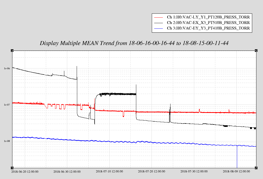
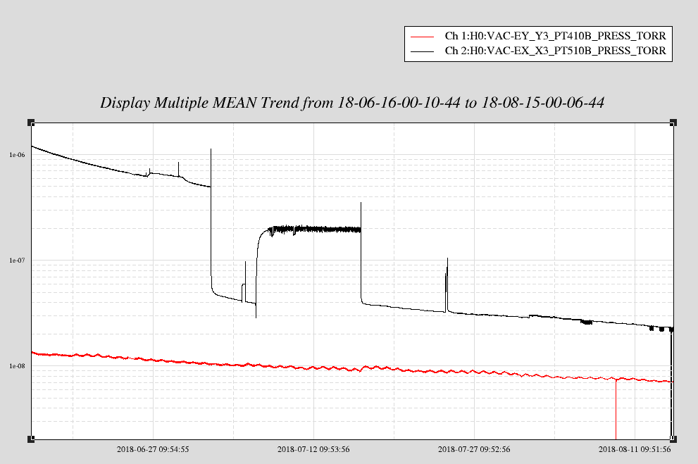
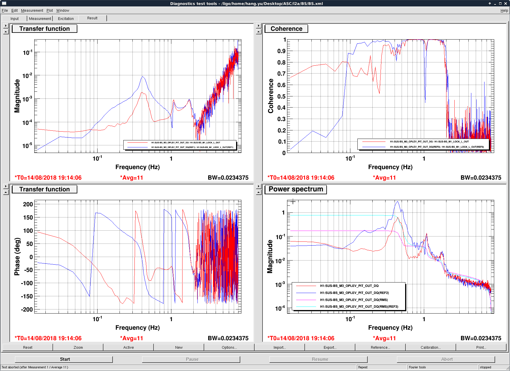
The ALS fiber polarization remote control changes the fiber polarization when it is turned on. In the attached plot you can see the behavior, the box was turned on at the time of the first large step.
I have also had difficulty correcting the polarization using the box.
Also, some of the channel names with it seem to not be in the DAQ (or for some other reason I can't find them in dataviewer). One example is H1:CDS-PULIZZI_ACPWRCTRL_MSR0_OUTLET_1_STATUS
my bad, I had created the ini file for the remote power channels (H1EDCU_CDSACPWR.ini) but forgot to add it to the DAQ master. It has now been added and will go into effect on the next DAQ restart.
I believe the issue on power up is that it is returning to the last position it was manually set to. From the manual: "When any waveplate is moved manually at the front panel, the MPC1 commits the position to memory within 3ms, thereby, automatically enabling the angular position of all waveplates to be reset on the next power-up. This short interval provides adequate time for the user’s angular settings to be saved in all but the most severe power failure conditions. It is important to note that this memory functionality does not exist, however, when motion commands are invoked via remote control, user entered pre-set programs, or the scramble mode. The resolution is also not saved in memory – on power-up it will be set to the default 0.15° per tick." This is not immediately seen on the medm screen because the position is not periodically polled. It is only polled after a remote positioning command is sent or if the 'Update' button on the medm screen is clicked.
I chose not to have it periodically poll the positions of the paddles, because there is no way for the software to know if the MPC is powered off, and if the MPC is powered off then the periodic polling would constantly report a communication timeout error.
Danny, Georgia, TVo
Turning on TCS CO2Y was difficult today for reasons unknown. CO2X is working fine as far as we know.
On July 24th 21:06:00 the CO2Y laser tripped for reasons unknown, normally when this happens it's due to a glitch in the flow sensor on the water lines and this will trip the laser controller with an error. Because we're not currently using the laser, we left it off. However, when we tried to turn it on today Georgia noticed that the sensors reading the laser power output directly from the laser head was particularly noisy even when the laser was turned off. We began to make sure the laser power supplies and interlocks were properly set for turning the laser on but it still wouldn't lase.
After consulting with Fil about the electronics, we saw that the Instek power supply on the chiller mezzanine looked like it was railing between 0 and 3 Amps, normally it should send a steady 21 amps to the laser. Also we saw that the 100V power supply that runs the PZT had a flickering LED, but Fil said that sometimes this happens and it doesn't necessarily mean something is wrong. The attached graph shows that the PZT MON was railing quite a bit and so I'm not sure if it's the power supply or the driver that's making it go crazy, investigation ongoing.
What we can try with the help of the EE guys is maybe individually swap the Instek power supply, the Kepco power supply, and possibly the laser controller in order to track down the bug. We double checked that there weren't any cables loose on the laser side on the table but everything seemed intact and the laser sees some power (4-7Watt spikes) but definitely not lasing like it normally does (steady 50W).
The first trend is a long time frame, and the second is over the course of a few hours which shows the PZT and the laser output spiking. The wiring matches E1100892 so we're still investigating.
Has the software routine that adjusts the PZT voltage for laser output power been disabled? If not, this
might be one reason why the PZT is railing.
Oh and I forgot to mention, there's the enable button on the front panel of the control chassis.
That enables some gating logic as I recall.
Thanks for the comments Peter
We enabled the gate and didn't get a response from the laser.
I think the software which moves the PZT around that you're referring to is the Guardian state which scans the PZT to find a good lock point for low frequency intensity stabilization using the PZT+chiller servo. This is usually done when the laser is already running at around 50 watts of laser output but our problem is that we can't get 50 watts to start with out of the laser.
Today we ran the usual Tuesday-maintenance charge measurements. The effective bias trend of ETMX over the last ~month suggests a normal slow accumulation of charge, possibly consistent with space charge polarisation, induced by exposure to the large fields from the ESD bias. The ETMY effective bias trend is harder to interpret, some quadrants are possibly trending away from zero, others seem constant. I do not think at this stage that switching the sign of the bias voltage will help us with ETMY. I also had a look at the time series as we step the bias voltage from -400 V to 400 V: changing the bias is visible in the optical lever signal. This seems to indicate some asymmetric charge distribution on the test mass.
The first attached plot shows the usual long trend of the effective bias for ETMX. I would tentatively suggest that the effective bias is trending away from zero, though more data would make this more convincing. My four-parameter measurement is consistent with this. All parameters except Beta-Beta2 are the same within reasonable uncertainty, and Beta-Beta2 has apparently increased slightly, also increasing the effective bias (now 37 V in pitch and 32 V in yaw).
The second plot shows the long trend of effective bias for ETMY. Only the lower left quadrant trends away from zero in a way reminiscent of space charge polarisation, the other two working quadrants seem stable. We have had the ETMY bias on at +400 V since July 19.
The third attachment is a screenshot of a striptool as we step through the bias voltages, for ETMX and ETMY. At each bias voltage, each quadrant is driven, which causes the higher frequency periodicity in the optical lever signal. The interesting feature is bias voltage showing up in the optical lever signal, which is significant in ETMY, and more noticeable in pitch. Any symmetric charge distribution, eg that caused by space charge polarisation, would not cause this, so this must be caused by some other source of charge (eg bump stop contact). I'm surprised that this doesn't show up as a large effective bias voltage in the usual measurements. Also, in the ETMY pitch optical lever signal there is a periodic offset, which occurs when the lower left quadrant is driven.
When compatible with other commissioning activities I would like to drive the ETMY bias and work out the beta+beta2 parameter from this, a back-of-the-envelope calculation based on the coupling to the op lev shown here suggests it's three orders of magnitude larger than ETMX.
Corner RGA scan and 60 day corner+EX+EY pressure trends.
EX RGA scan and 60 day pressure trends of both EX & EY attached.
EY RGA scan and 60 day pressure trends of both EX & EY attached.
WP7774 h1sush2a OSS fiber replacement
| serial number | cable label | |
| old | UA10490001.A | h1sush2a |
| new | UA10510002.A | h1sush34 |
which leads to the question if h1sush34's cable was on top of the rack, what is h1sush34 using
| serial number | cable label | |
| h1sush34 | UA11040002.A | no label |
There is a spare OSS fiber at h1oaf0 following a past upgrade
| serial number | cable label | |
| old | UA12110005.A | h1oaf0 |
| new | UA12120006.A | ONESTOP 2 |
For all the front end computers, their OSS cable has the computer name as its label except for the following:
| host | OSS cable label |
| h1lsc0 | no label |
| h1oaf0 | ONESTOP 2 |
| h1sush2a | h1sush34 |
| h1sush34 | no label |
| h1susauxh34 | no label |
And finally on the top of the MSR rack, there are the following OSS cables
|
h1susauxh34 (good spare?) |
| ONESTOP 1 (good spare) |
|
ONESTOP 3 (good spare) |
| no label (good spare) |
| h1oaf0 (behind h1oaf0, possibly bad) |
| h1sush2a (behind h1sush2a, possibly bad) |
WP7765 CDS WAP configuration standardization
Dave, Carlos:
All 6 CDS WAPs (wireless access points) now share a common networking configuration.
WP7774 Replacing h1sush2a One Stop fiber
Richard, Dave:
As part of the investigation into h1sush2a's recent instability, we replaced the One Stop fiber for a spare line today. Details in separate alog.
WP7770 ISI-HAM[2,3] GS13 cable and model switching
Hugh, Dave:
New models for h1isiham[2.3] were installed to match the GS13 field cabling changes made today. Also the updated BIO parts were added to the models.
WP7749 Removal of temporary GS13 fast channels from frame
Hugh, Dave:
New h1isiham[2,3,4] models were installed which remove the temporary GS13 DQ channels from the frame (six per model).
Vacuum Controls end station ion pump addition
Patrick, Dave:
h0vacey was modified to add IP17, h0vacex was modified to add IP18. A new INI file was created for each system.
Slow Controls Wind Fence channels added to h1ecaty1plc1
Patrick, Dave:
h1ecaty1plc1 was modified to add its wind fence channels. A new INI file was created.
DAQ Restart
Dave:
The DAQ was restarted at 13:07 PDT to support:
h0vacex and h0vacey new IP channels.
h1ecaty1plc1 new wind fence channels.
h1isiham[2,3,4] removal of temporary GS13 channels.
BTW: h1sush2a stopped running at 13:19 UTC today (06:19 PDT), just in time for maintenance.
model restarts logged for Tue 14/Aug/2018
2018_08_14 10:32 h1iopsush2a
2018_08_14 10:32 h1susmc1
2018_08_14 10:33 h1iopsush2a
2018_08_14 10:33 h1susmc1
2018_08_14 10:34 h1susmc3
2018_08_14 10:34 h1suspr3
2018_08_14 10:34 h1susprm
2018_08_14 10:37 h1isiham2
2018_08_14 10:37 h1isiham3
2018_08_14 13:00 h1isiham4
2018_08_14 13:05 h1isiham4
2018_08_14 13:09 h1broadcast0
2018_08_14 13:09 h1dc0
2018_08_14 13:09 h1fw0
2018_08_14 13:09 h1fw1
2018_08_14 13:09 h1fw2
2018_08_14 13:09 h1nds0
2018_08_14 13:09 h1nds1
2018_08_14 13:09 h1tw0
2018_08_14 13:09 h1tw1
TVo, Danny
To get a better idea of how the picomotor movements effect the movement of the Hartmann beam across the ITM, we decided to move them by a larger amount. To make sure there isn't any clipping I went out to the HWS table and removed the Hartmann plate to view the beam on the ccd while moving.
The following moves were made:
ITMX upper periscope mirror: 700 counts to the right
ITMX lower periscope mirror: 500 counts to the right
ITMY upper periscope mirror: 500 counts to the left.
Attached are the current picomotor settings.
A ring heater test will be coming soon.
TVo, Georgia, Danny
After a discussion at the commissioning meeting about using CO2X for a contrast defect measurement, we moved the Hartmann beam for ITMX back to where it was before this comment in order to make an attempt at centering CO2X sometime tomorrow. The plan is to do a contrast defect measurement and have CO2X (about) centered sometime before Friday so we can use CO2X to improve it on Friday.
WP 7773 The PLC code on h0vacex has been updated to add IP18. The PLC code on h0vacey has been updated to add IP17. I also took the opportunity to split the PLC code for the BPG 402 gauges into separate revisions to address the problem I noted in alog 43341. The high voltage has been turned back on at both end stations. I burtrestored both to 6 am today.
We updated the L2P FF filter in BS M1 stage.
The resultant M1 L drive to BS oplev pitch TF is shown in the first attached image. The blue curves were for the old L2P FF (only a scalar with gain 0.002), and the red ones were for the new, freq-dependent FF at the M1 stage.
The measured FF filter = L2P/P2P appeared to be quite hard to fit, partly due to that I did not took a long enough measurement to integrate for good SNR. Thus for now we only focused on the main SUS resonance at ~ 0.5 Hz, and the microseismic band ~0.2-0.3 Hz, while sacrificing the earthquake band < 0.1 Hz. It should be fine in the full lock state when we could relying on the feedback to handle the <0.1 Hz band, but whether the current FF would be beneficial for the lock acquisition would still need to be tested.
Somehow in the coherence plot (top-right) the reduction in the main sus resonance was not apparent (it might be due to the fact that the DTT TF is a biased measurement, as the measurement noise term would not vanish in the auto-correlations used for computing coherence; see, e.g., Evan Hall's thesis, Appendix A). Nonetheless in the TF plot (top-left) we could see roughly an order of magnitude reduction at 0.5 Hz. The measurement used to fit the TF was done with the oplev damping off, and the attached plot showed the result with the oplev on. Thus it seemed that the FF should work in either case.
In the FF_fit_vs_data.pdf we show the fitted TF (blue) and the data (orange). The foton filter we use currently is:
zpk( [ 0.000000e+00+i*0.000000e+00; -1.400000e-01+i*0.000000e+00; -2.043560e+00+i*0.000000e+00; 1.348996e+00+i*0.000000e+00; -1.028492e+00+i*8.718815e-01; -1.028492e+00-i*8.718815e-01; ], [ -5.000000e-03+i*0.000000e+00; -2.000000e-01+i*0.000000e+00; -1.720109e+00+i*0.000000e+00; -1.734806e+00+i*0.000000e+00; -2.301921e+01+i*0.000000e+00; -1.335285e-01+i*2.691426e+00; -1.335285e-01-i*2.691426e+00; -2.199115e+01+i*3.808979e+01; -2.199115e+01-i*3.808979e+01; ], 4.584153e+02 )
I've updated the Actuator Tuning Spreadsheet accordingly (remember to switch from personal google account to ligo.org authentication in order to view). Thanks Hang!
After the restart of h0vacey, PT423 did not engage. While we wait for a cosmic ray to trigger this gauge, I've bypassed it from the cell phone alarms system. This will be standard procedure following code restarts, providing the bypass period overlaps with the operator's shift (i.e. no unattended bypass period).
Bypass will expire:
Tue Aug 14 15:48:54 PDT 2018
For channel(s):
H0:VAC-EY_Y1_PT423B_PRESS_TORR
PT423 is now active, bypassed has been turned off.
WPs 7770, 7749, FRS 11049. DaveB, RichardM, JimW, HughR
Conclusion--Yes the model and the hardware were at cross purposes as Interface Chassis 1 had GS13s corners 1 & 3 while the BIO switching via the model thought it was corners 1 & 2.
Details:
Rewired the interface chassis for HAMs 2 & 3 to have corners 1 & 2 GS13s to chassis #1 and corner 3 to go to chassis #2 (switched cables 2 & 3.) Rewired the top level models for HAM2 & 3 to reflect this field wiring change. Dave also swapped out the deprecated digital IO cds RCG part with the current latest version. Removed the GS13INF_OUT channels from the DAQ list in the common model and the one occurrence of "DACKILL", an annotation element. There should be no more user model DACKILL parts.
After Dave rebuilt, checked etc, and the model was restarted, ran the ISIs in DAMPED mode and toggled each digital filter on the GS13s. No problematic wildness occurred. Then ISOLATED the platform and used the commands scripts to toggle the filters--all good. Finally, changed the Guardians to include the GS13 switching--the GS13s switch to high gain whitening off after isolating and switches back when deisolating or tripped. Exercised the platforms via the guardian and no issues; the GS13 change state with out bothering the platform much less tipping them violently.
Finally.
The PEM corner station AA chassis have some dead channels and will need to be removed for repair: Channel 7 (bottom chassis) - (MIC EBAY) Channel 2 (bottom chassis) - (MIC HAM7) Channel 29 (2nd from bottom chassis) - (MIC INPUTOPTICS/HAM2) Cables will be run for accelerometers in the following locations this Tuesday: HAM 1 - X, Y, Z (top) HAM 2 - X HAM 5 - Y, Z (top) HAM 6 - Y BSC 2 - X, Z (bottom) BSC 3 - Z (bottom)
Due to a misunderstanding, the cables didn't get pulled today. They will be pulled next Tuesday unless opportunity knocks before then.