[Keita, Gabriele]
The ISS second loop is working fine, we could operate it at 36 W input power, with a bandwidth of about 16 kHz, all three boosts on, with a open-loop gain of 41 dB at 1 kHz.
Today we continued out work on the ISS second loop. At the beginning we could engage the second loop at 2 W input power, with a gain of 26 dB, and then increase the power to 5 W. However, from 5 W up, it was not possible to have a second loop unity gain frequency higher than about 1-2 kHz. If the gain was any higher, some intermittent oscillation were visible in the time series and spectrum of the ISS signals.
We decided to go to the floor and measure the second loop open-loop transfer function with the analog input. There was a large peak at about 82 kHz, giving us less than 5 dB of gain margin. This explained why we could not increase the ISS second loop gain, and why we failed increasing smoothly the power. We traced the problem to a gain peaking in the ISS first loop: by reducing the first loop common gain from 13 dB to 8 dB, the peak was gone and we were able to smoothly increase the ISS second loop gain.
With an input power of 36W (the maximum we could get) we set the ISS second loop gain to 20dB, obtaining a unity gain frequency of about 16 kHz. We then disabled the AC coupling loop (by holding the output and disabling the input) and could engage all three boosts. The ISS second loop open-loop gain at 1 kHz was 41 dB. There is no visible transient when engaging or disengaging the boosts. NOTE: this measurement was taken with an input power of 2 W and increasing the ISS second loop gain to 40 dB to make the boosts stable.
The first plot attached below shows the open loop transfer function of the ISS second loop with the AC coupling on (blue) and off (red), without any boosts. You can't engage boosts with the AC coupling on.
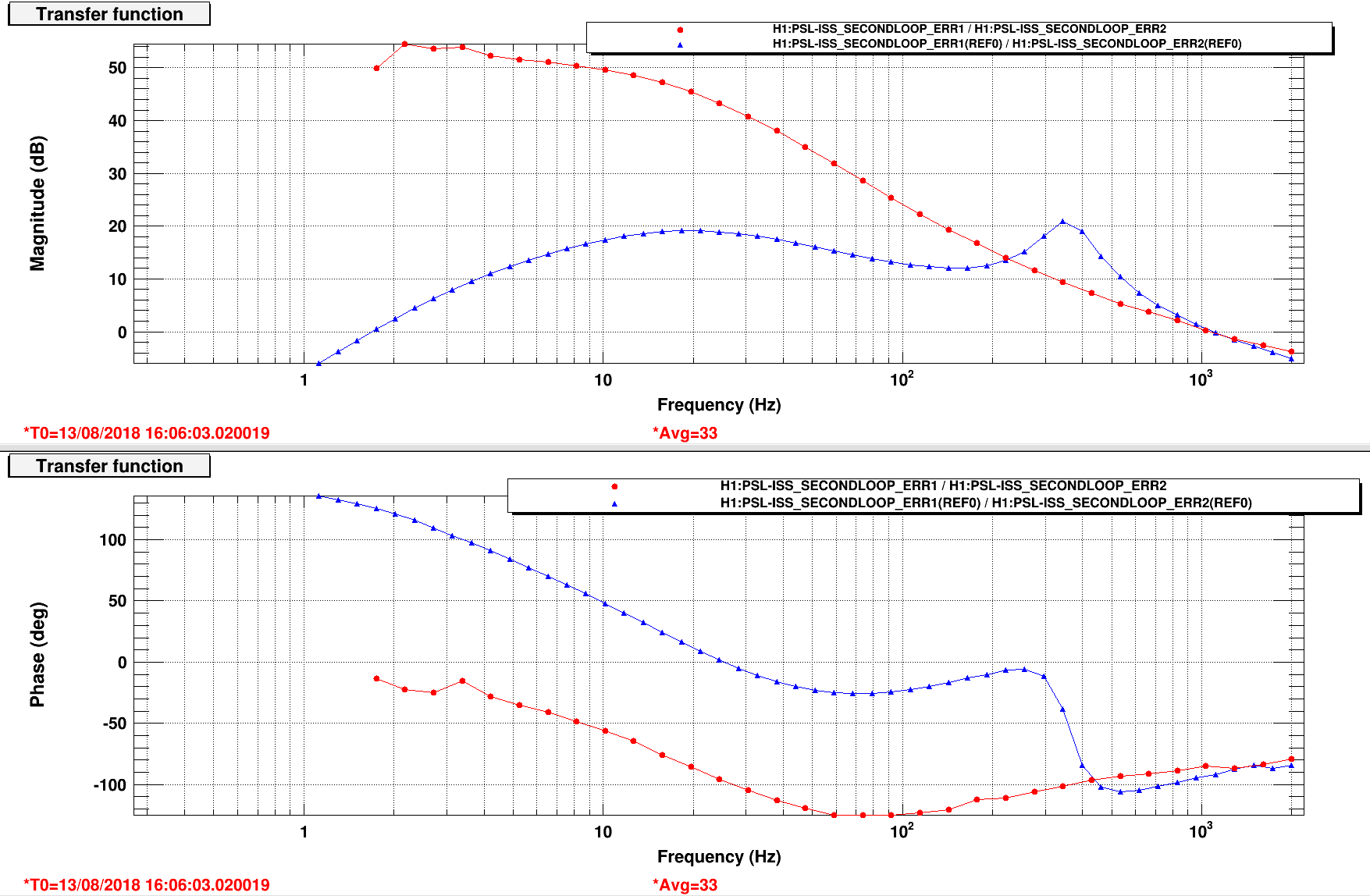
The second plot shows the in-loop (red and green) and out-of-loop (blue) error signals without boosts (green) and with boosts (red).
The third plot shows some measured OLTF with AC coupling on: BLUE = 2 W gain 26dB, GREEN = 4 W gain 26 dB, BROWN = 8 W gain 36 dB, pink = 8 W gain 20 dB, CYAN = 16 W gain 17 dB, RED = 36 W gain 20 dB
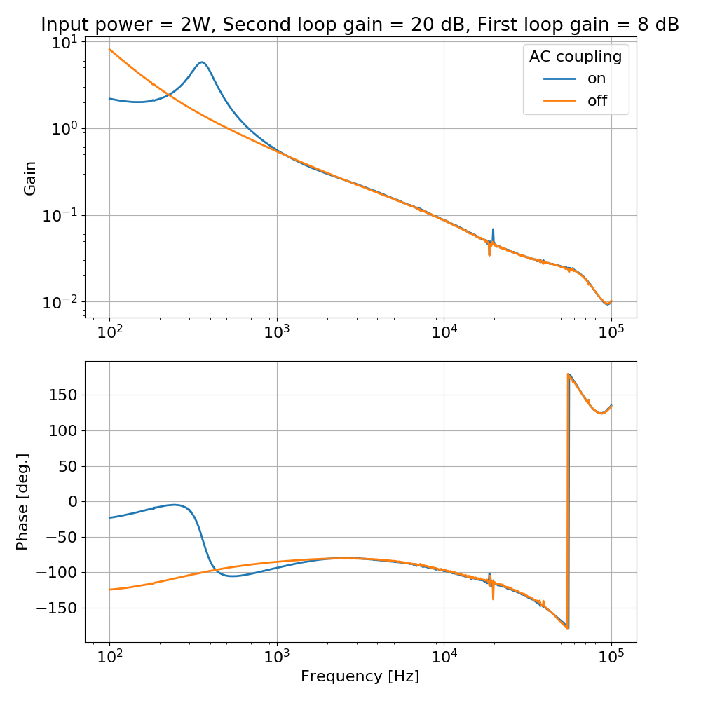
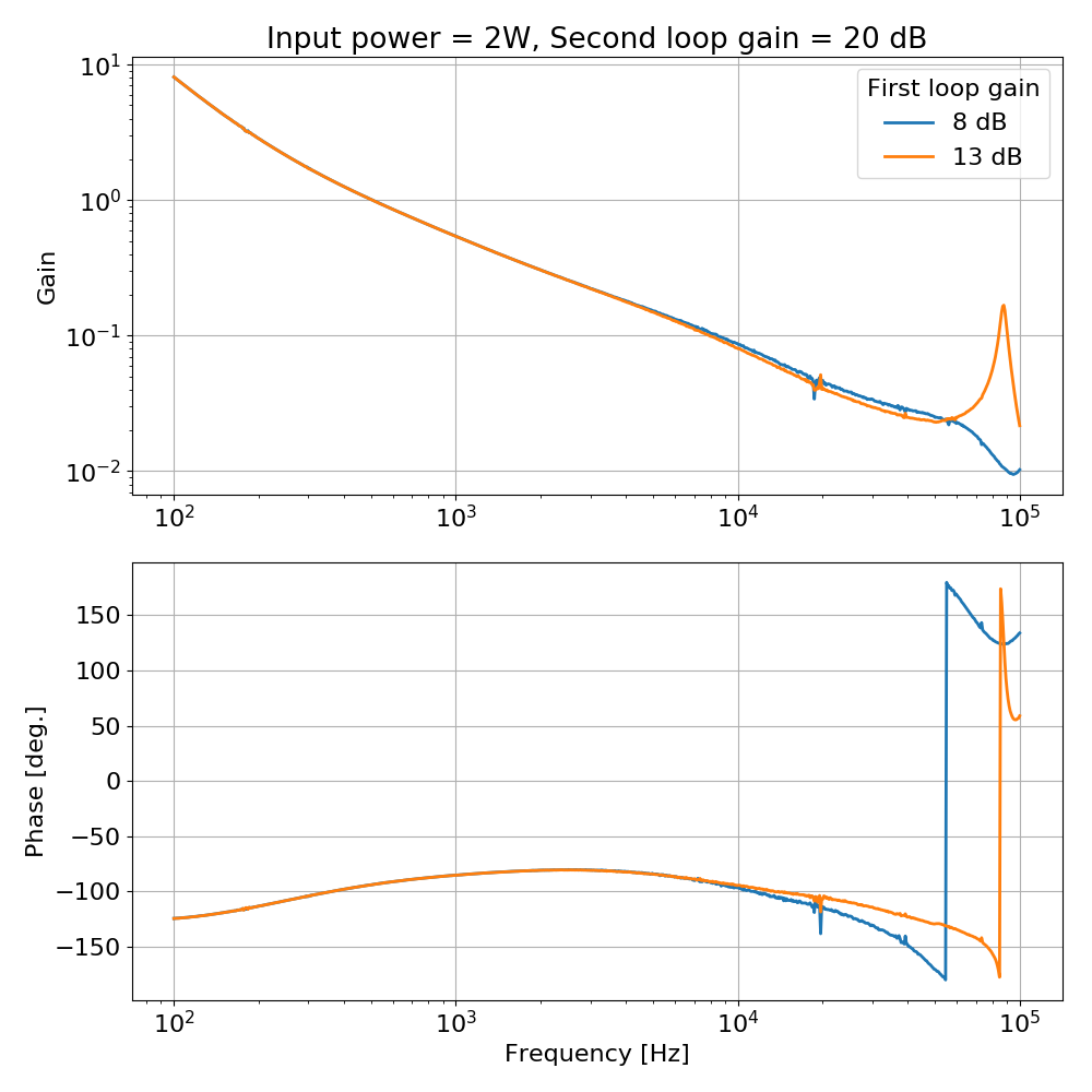
The fourth plot shows the effect of the ISS first loop gain: there is gain peaking at ~80kHz when the first loop gain is 13 dB, no peaking when the gain is 8 dB.
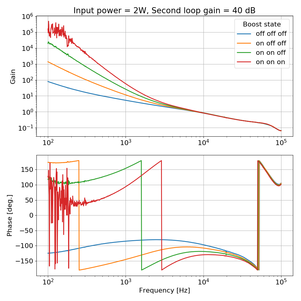
The fifth plot shows the engagement of the boosts. NOTE: this measurement was taken with an input power of 2 W and increasing the ISS second loop gain to 40 dB to make the boosts stable.
The sixth plot shows the effect of switching on and off the AC coupling loop.
Danny, Georgia
This morning we worked on the ETMY HWS table. All mirror labels are referenced from this diagram.
This looks very similar to what we got with the 50 micron fiber in May: aLOG 42204. Where is the beam from the fiber launcher converging in this system?
I had expected the 50-micron fiber to improve things but it, counter-intuitively, made the beam much bigger. With nominally the same NA on the fibers, the extra modes in the 200 micron fiber should produce a larger beam size. This suggests that the mode-matching is not exactly what I think it is.
One possible test is to scan the range of the translation stage (in steps of 2mm) and get images of the beam profile on the HWS for each step with the fiber launcher iris fully open, partly open (say 6mm diameter) and almost completely closed (say 2mm diameter aperture).
A continuation of alog 43151.
I noticed the IMC in power was running at 37W, and the new large area EOM PD was reading much less than that, so I adjusted the calibration of H1:IMC-PWR_EOM_OUT16, and H1:PSL-EOM_A_DC_POWERMON channels, so they now read 37W. Snapshots of changes attached.
Note h2b, not h2a.
h1sush2b experienced a timing glitch at 13:09, we think due to activity in the CER. IO Chassis comms were not lost, I restarted the models after they were safe'd and sdf'ed (h1susim, h1sushtts{rm1, rm2}).
With the return of high pressure over the area the haze and smoky conditions have also returned. There are dozens of fires burning all around the west and northwest, which are contributing to the degraded air quality. See the attached NW-Fires map.
These conditions are forecast to persist until Wednesday at the least.
Exercise caution when working outside. It is best to stay inside with you have respiratory issues or are experiencing things like burning/watering eyes, burning in your lungs, shortness of breath and/or persistent coughing. If symptoms do not improve you should consult your doctor.
Morning Particle Counts (per cubic foot of air)
| Location | 0.3um | 0.5um |
|---|---|---|
| Outside the staging building receiving/man door | 6.8M | 4.0M |
| Outside the control room entry door | 6.6M | 4.3M |
| In OSB office area (a top Patrick's cube | 5.0M | 1.1M |
| In the control room | 12K | 2.5K |
| At the LSB lobby reception desk | 7.8M | 3.1M |
The PEM corner station AA chassis have some dead channels and will need to be removed for repair: Channel 7 (bottom chassis) - (MIC EBAY) Channel 2 (bottom chassis) - (MIC HAM7) Channel 29 (2nd from bottom chassis) - (MIC INPUTOPTICS/HAM2) Cables will be run for accelerometers in the following locations this Tuesday: HAM 1 - X, Y, Z (top) HAM 2 - X HAM 5 - Y, Z (top) HAM 6 - Y BSC 2 - X, Z (bottom) BSC 3 - Z (bottom)
Due to a misunderstanding, the cables didn't get pulled today. They will be pulled next Tuesday unless opportunity knocks before then.
Sheila, Haocun, Nutsinee
This morning we had a chance to inject the squeezer seed beam with the main interferometer misaligned while people were working on HWS and the ISS. We didn't have trouble finding the beam or aligning it to the SRM angle we have been using recently for locking. Attached is a screenshot of the slider values for which we can close the AS centering loops on the seed beam and close the OMC QPD loops.
We took an OMC scan, but it is possible that the seed beam was resonating a higher order mode, so we will have to return to this.
12 hours of minute trends where the winds where over 5 meters/second(mps), [~11mph] are attached. First is the means of the three sensors overlayed. Looks okay with some rough times.
Second plot has the three sensors plotted separately and the differences between the sensors; ideally the difference is zero. Some areas of larger (~1mps) diffs and other times where they are very small. The bimodal trend may be from shifty directions, gustiness, or maybe the trends themselves. It's a long stretch of time but I'll zoom in and check second trends and full data where able.
Second trends show the same thing. I suspect the direction and speed of the wind combined to either cause physical interference between the anemometers or maybe the wind itself was altered.... Given the sharp On/Off nature of the differences, I suspect the former. I'll try to get out to examine the anemometers for impact evidence.
I also noticed the discrepancy between the wind sensors for higher wind speeds. However, I think that this is because of the differences in wind direction during this time period/the placement of the wind sensors. Within this windy period, I focused on 3:00-9:00 PM on August 11. I attached plots of the wind speed for each sensors, the wind direction, and the differences between the sensors. From 3:00-5:30 PM, the average wind direction is about 100 degrees. This corresponds to a much larger difference between wind sensor 2 and the other sensors. After 5:30 PM, the wind changes direction. This corresponds to a relatively uniform difference between the three sensors. Based on this, I don't think we need to be concerned about sensor 2 as this discrepancy seems to be because of changes of wind direction. I think that we are ready to move the sensors to the fence.
Laser Status: SysStat is good Front End Power is 33.7W (should be around 30 W) HPO Output Power is ~74W Front End Watch is GREEN 70W Watch is GREEN PMC: It has been locked 0 days, 0 hr 0 minutes (should be days/weeks) Reflected power = 15.07Watts Transmitted power = 41.82Watts PowerSum = 56.89Watts. FSS: It has been locked for 0 days 2 hr and 4 min (should be days/weeks) TPD[V] = 1.969V (min 0.9V) ISS: The diffracted power is around 3.1% (should be 3-5%) Last saturation event was 0 days 0 hours and 20 minutes ago (should be days/weeks) Possible Issues: LRA out of range, see SYSSTAT.adl
Today: Hartmann table work at end Y Tuesday: Property services audit Vacuum wiring at both end stations Charge measurements Concrete pouring at mid X and behind VPW PEM cable runs for accelerometers in LVEA HAM1 HEPI loops updated to be more aggressive HAM2/3 model change and test Moving anemometers at wind fence PSL PD commissioning PSL IO photos WAP updates 6-8 am Beckhoff topology change at end Y
All plots seem nominally ok.
Restart of h1sush2a following loss of communications with IO Chassis.
model restarts logged for Sat 11/Aug/2018
2018_08_11 08:31 h1iopsush2a
2018_08_11 08:32 h1iopsush2a
2018_08_11 08:33 h1susmc1
2018_08_11 08:33 h1susmc3
2018_08_11 08:33 h1suspr3
2018_08_11 08:33 h1susprm
Sheila, Craig, Georgia
We've had another difficult day for locking, perhaps because it has been windy but there might be something else going on. Here are a few things that we did:
[Nergis, Haocun]
After locking the OPO, we were able to get a locked SEED beam on the SQZT6 for homodyne work.
Main steps:
We did the visibility maximization process with PD2, getting 96%, but it was only 92% for PD1. Then we found that when the homodyne is balancing for the LO beam, the two diodes read very different values with the SEED beam. I checked the polarization of the two beams, and both of them are well s-polarized.
This led me to go back and recheck the diodes of the homodyne, finding that PD2's reading is only about half of value of PD1 when shining the same beam on them. Also, Daniel and I inspected with an IR viewer, and found that there is a bright reflection from PD2. We probably need a new diode for PD2, but this means the mode matching is good enough, and we can still use the current set up to work on the CLF and LO loop.
Some changes of the mode matching solution: (I will update the diagram later soon.)
Then we found that when the homodyne is balancing for the LO beam, the two diodes read very different values with the SEED beam
This is very strange to me. Do you get the large reflection with the LO or seed beam? The reflection suggests the issue is with the diode, but this suggests something strange with the BS. If the diode has a large reflection, then perhaps to balance the LO, the BS is tilted strongly and the seed has the opposite R/T and so looks highly unbalanced. It sounds like the diode is so bad that you shouldn't be able to get the two diodes balanced from the BS though. If bad diode + unbalanced BS = balanced photocurrent were the case, then you shouldn't be able to get such good visibility in one of the diodes though I would think. Anyway, we can ship diodes, but I'm just wondering if somehow the BS or beamsize on the diodes could cause what you describe. I recall that the diodes aren't always perfectly flush with the board and so can hit at differing angles, which can also affect the reflection.
SQZT6 Table Layout Attached
The homodyne balancing problem was solved. Mainly by adjusting the beam size and angle shining on the diodes.
Craig, Hang, Georgia, Sheila
We've been having trouble locking, probably because of the wind and a small EQ, and perhaps because the IMC UGF was too high. We decided to use some single bounce time to investigate why we can't engage the OMC ASC. We were able to engage it when we were doing OMC scans just over a week ago. We haven't been able to lock the OMC because we rail the OM3 +OMC suspensions if we try to engage the QPD loops.
Hang and I noticed that the picomotor for AS_A was accidentally moved on August 7th. Even though the settings were set back, we suspect that the pointing onto the QPD may not have been restored because of the hysteresis of the picomotor. On August 7th the AS_C pico was moved for a better SR2 pointing through the OFI.
Craig used his script that restores optics to a given time using the top mass witnesses to restore SR2, OM1,2,3 and the OMC to their alignments from July 31st at 22:53 UTC, which is the time of one of our single bounce scans. We saw that this brought the OMC QPDs closer to their lock point, and pico'd AS_A to center the beam on the diode. AS_B pico has not moved since Thomas Vo adjusted it in June so we didn't touch that. Once AS_A was centered here we closed the AS centering loops, and pico's AS_A while it was in loop to bring the OMC ASC error signals to zero.
After this was done we were able to close the OMC APD loops without a problem, and then walked SR2 back to it's more recent alignment. The OMs are still not railed.
Dear Sheila, what you say about the Picomotors rings true. Calum and I did some investigations into the Picomotor hysteresis. The method by which the Picomotor achieves motion relates to a stick-slip phenomenon. As each Picomotor is preloaded with a certain force, there is an intrinsic tendency for a step in one direction to be unequal in motion to a step in the opposite direction. In addition, this highly friction dependent phenomenon is rife with hysteresis. Simple summary is that if you step N numbers of steps for a Picomotor, you will never know exactly how to reverse this action without a secondary measure of motion.
Past experience shows that a backward motion may be no more than 80% of the forward motion. So the resulting alignment error can be as large as 20% of the full motion.
We have started a 1 hour ring heater test at 04:00:00 UTC. The ring heater on ETMX will run for 1 hour at 3W.
We have shuttered the ALS green beam while we do this test, it can be unshuttered in the morning.
I will schedule another identical ETMX ring heater test tonight at the 04:00:00 UTC, same parameters, from ZOTWS14.
Corner station RGA scan attached. N2 peak is high. We will monitor to see how it decreases with time. SEM voltage set to 1300V.
Corner station pressure trend attached. Notice the flat trend followed by an obvious change in slope.
Corner station RGA scan this morning. H2, H2O, N2 levels are about the same from 10 days ago.