WP 7758 I have linked the variables in the system manager and committed it to svn. The additional channels are now in EPICS: H1:PEM-X_FENCE_WIND_SPEED_1_MA H1:PEM-X_FENCE_WIND_SPEED_1_MPS H1:PEM-X_FENCE_WIND_SPEED_2_MA H1:PEM-X_FENCE_WIND_SPEED_2_MPS H1:PEM-X_FENCE_WIND_SPEED_3_MA H1:PEM-X_FENCE_WIND_SPEED_3_MPS H1:PEM-X_FENCE_WIND_SPEED_4_MA H1:PEM-X_FENCE_WIND_SPEED_4_MPS H1:PEM-X_FENCE_WIND_DIR_1_MA H1:PEM-X_FENCE_WIND_DIR_1_DEG H1:PEM-X_FENCE_WIND_DIR_2_MA H1:PEM-X_FENCE_WIND_DIR_2_DEG H1:PEM-X_FENCE_WIND_DIR_3_MA H1:PEM-X_FENCE_WIND_DIR_3_DEG H1:PEM-X_FENCE_WIND_DIR_4_MA H1:PEM-X_FENCE_WIND_DIR_4_DEG Only the 1st, 2nd and 4th wind speeds and the 1st wind direction have working sensors.
Sheila, Georgia, Craig
LSC:
This afternoon we had difficulty locking the interferometer, in part because we didn't have the same alignment as we had tuned the CARM offset reduction for. Georgia and Jenne did an initial alingment that brought us back to a similar recycling gain to what we had sunday and monday evenings. As soon as the control room quieted down and we stopped trying to use DRMI ASC the interferometer locked easily with the same guardian sequence and settings that worked earlier.
We manually went through the steps in DRMI_ON_POP, but based on loop gain measurements (attached) we opted not to engage the MICH boost or turn the DARM gain up by the factor of 3.5 that the guardian would have used (we have been skipping a gain reduction by 2 step in the CARM offset reduction so this mostly comes out in the wash).
ASC:
We made some changes in the PREP_ASC_FULL_IFO, (it turned on PRC1 and PRC2 by mistake, and was missing a run state. Now it is turning the gains to zero.) Now we are able to let the gaurdian proceed to this state. We have been manually adding gain to DHARD P by engaging FM3 and increasing the gain to -30
We went to ISCT1 and found that the beam was falling off of POP X, so Georgia centered it. We also found that the input matrix for DC6 was used for something else. We should add the DC6 settings to the guardian to make sure they get set.
We moved PR3 in pitch and saw that the signal was mostly in Q, so we shifted the phases by -90 degrees. (When I accepted this in SDF I see that there are many phase changes in the ASC SDF, it might be helpful to accept them). We checked this with an 8 Hz dither to PR3 M3. After that we were able to close the PRC2 loops with the gain that is in the guardian. They are only going to M1. We did not try engaging the integrator, but it should be fine.
We checked that the lock point of INP1 looks good, and the pitch loop seemed to turn on fine with the gain of 1 that is in guardian, but yaw went in the wrong direction.
I think that we the most efficient way to make progress is to find an alignment that gives us a better recycling gain before we try to use the DRMI ASC. Our locking today started to go much more smoothly as soon as we stopped trying to use the DRMI ASC. The easiest way to search for a better alignment would be to close more of the ASC loops in full lock and try moving spot positions.
J. Kissel
Using the lock stretch that Sheila called out in LHO aLOG 43263, I gathered data that shows the new violin mode forest after we've replaced ETMX, ETMY, and ITMX (with ITMY been exposed to air for ~9 months, which undoubtedly also changes the violin mode frequencies). Attached are comparisons of the Fundamental (~500 Hz), 1st Harmonic (~1000 Hz), and 2nd Harmonic (~1500 Hz) DARM ASDs from O2 (after the July 2017 EQ) and this most recent lock stretch.
I've begun to update the LHO violin mode table (Violin_Mode_Table_v2) in prep for identification of this new forest. I've used the in-air data from LHO aLOGs 40525, 42180, 38857.
So far, I can identify 29 of the fundamental 32 modes, with a 2 mHz resolution. They're tabulated below (and not yet in the table), since I've not yet associated them with a test mass (though some appear to be "obvious" given the large separation).
In hopes to identify the mode Sheila calls out as the worst, I've pushed a 503.085 Hz filter to all new test masses, on MODE 1. This way when we do get a decent lock stretch, we can identify the mass "passively" by turning on the filter with some small gain, to see on which test mass we get action. As before, we'll started by assuming the mode is controllable by driving in Pitch.
| Frequency | Potential Match w/ in-air |
| 501.553 | IY |
| 501.628 | IY |
| 501.692 | IY |
| 501.755 | IY |
| 502.784 | IX |
| 502.909 | IX |
| 503.085 | EY / IY |
| 503.198 | EY / IY |
| 503.676 | EY / IY |
| 503.733 | EY / IY |
| 504.143 | EY / IY |
| 504.176 | EY / IY |
| 504.606 | EY / IY |
| 504.719 | EY / IY |
| 504.850 | EY |
| 504.889 | EY |
| 504.942 | |
| 505.077 | |
| 505.186 | |
| 507.360 | EX |
| 507.493 | EX |
| 508.844 | EX |
| 508.938 | EX |
| 510.714 | EX |
| 510.723 | EX |
| 511.180 | |
| 513.405 | |
| 516.678 | EX |
| 516.778 | EX |
In order to gather this data, I just used the standard violin mode templates from O2 (see LHO aLOG 37921), which are linked off of the VIOLIN MODE monitor MEDM screen.
Remember, we tried to separate the mode frequencies between test masses, and cluster a given test mass, to make them more easily identifiable (see E1700342, G1701332), but the reality of implementing such a system didn't work out as planned (an already minimal supply of fibers, few sets of fiber breakages, changes in frequency after welding and annealing, etc.). See some details in LHO aLOGs 41216, 40292, and 38965, but most my memory of the failure of the plan is verbal from telecons -- perhaps others can retrace the steps.
I have started adding some violin mode bandpass filters for ETMX, but have not had a change to test them out yet.
I added bandpass, +60, -60 degree phase shifts for 508.36 Hz, 508.844 Hz, 510.714 Hz and 516.678 Hz, in the filter banks under Mode2, Mode 11, Mode 12, and Mode 13 respectively.
The 503.085 Hz mode is on ITMY, and has been damped with the MODE1 filter, with -70 gain, no extra phase ( this can definitely be tuned in the future though), and feedback to pitch.
Note: This comment should have appeared after Georgia's comment below.
The link to the wiki page above isn't working. Here is a link : Violin mode table v2
504.891 Hz is on ITMX, can be damped with a gain of -3 and a phase of -60 degrees. (FM1 in ITMX mode 1 is a 50 mHz wide filter centered at 504.891, this is narrower than our other filters because there is a nearby mode at 504.953 Hz.)
Unfortunately it looks like we have two modes on ITMY that are only separated by 4 mHz. I was able to damp a mode at 501.629 Hz on ITMY with the same MODE4 filter Georgia used to damp the mode at 501.625Hz, but with a negative gain and +60 degrees of phase. I was suspicious that these could be the same mode, so I compared a spectrum with a resolution of 2 mHz from 2:42 UTC today (before Georgia damped ITMY) with the lock at 5:09 UTC, and it looks like they are actually two modes separated by about 4mHz. (Screenshot)
To deal with this, I created a filter called doublet in MODE4 which has 0dB of gain and a phase of -31 degrees at 501.624 and -3dB with -147 degrees at 501.628 Hz. A brave soul might be able to engage this filter with the bandpass that Georgia made earlier and no additional phase shift to damp both modes at once.
Edit: I got to try the doublet filter but it isn't very effective at damping the higher frequency mode which is rung up at the moment.
I also tried to damp 501.755Hz, but I don't think this is on ITMY. I copied my filter to ETMX MODE3, and tried 2 phases of pitch, but we lost lock before I could try yaw or longitudinal for ETMX.
I added a few more violin mode damping filters for ITMY. I promise I'll update the wiki table with this information soon.
The 503.198 Hz mode (MODE5) is on ITMY YAW, and was damped easily with -10 gain (haven't optimised any of the phases yet).
I tried to tackle the ITMY forest around 501.6 Hz but had trouble with cross coupling, accidentally ringing up neighbouring modes. I narrowed the filters and had some success damping
- The 501.625 Hz mode in pitch with a gain of 15 (filter bank MODE4)
- The 501.555 Hz mode in yaw with a gain of 20 (filter bank MODE6)
- The 501.692 Hz mode had some success with a gain of -5, before we dropped lock for other reasons. Will come back to it (filter bank MODE7).
J. Kissel
We don't yet have enough long lock stretches to get more precise than 0.005 mHz resolution, but I attach a few 1 mHz BW ASDs in the recent lock stretches that Sheila mentions (and some that I've found / reported),
- 2018-08-21 07:25 - 07:54 UTC,
- 2018-08-21 02:43 - 03:11 UTC,
- 2018-08-20 21:50 - 22:25 UTC,
- 2018-08-15 19:19 - 20:48 UTC,
where, because the last from several days ago, was 1.5 hrs, I was able to get a 0.5 mHz BW ASDs.
The message -- I can concur with Sheila's assessment that these two modes at 501.625 and 501.629 are 4 mHz apart -- however, only in 1 of the 4 measurements is the lower, 501.625 mode rung up. Thus, I think (thus far, we're not yet on DC readout) this is a weakly coupled mode that was rung up by our damping exploration attempts, so if we can design a filter that only tackles 501.629, then we might be OK. (It may not even be ITMY, but the 4 mHz mode separation does smell very much like a barely-elliptic mode splitting.)
I think Sheila and Georgia are on the right track of refining the band-pass filter to be that much more narrow. Mode frequencies for these violins are stable to temperature and test mass alignment at the ~10 microHertz level, so I think plant inversion -- or at least a very narrow (0.5 mHz) band-pass -- might be OK (see second attachment; figure 2 from G1601163 and/or G1700038).
Updated the table with some gains and phases for modes 504.606 Hz, 504.719 Hz, 504.85 Hz, all on ITMX and requiring low gains (<~5). And 504.953 Hz on ITMY (high gain, -30).
Posting this screenshot as a message to all the other v-modes out there. Blue reference is before damping, red is after.
In response to Sheila's request to compare the two following locks:
Aug 21 2018 02:42:00 UTC > Aug 21 2018 03:11:00 UTC [1218854538 > 1218856278]
Aug 21 2018 05:09:00 UTC > Aug 21 2018 05:29:00 UTC [1218863358 > 1218864558]
I ran 1mHz resolution PSDs. Results are below.
LOCK Aug 21 2018 02:42:00 UTC
Freq. [Hz] SNR
501.3750 77
501.5556 33815
501.6251 10114
501.6913 2815
501.6972 184
501.7553 181884
501.8750 76
502.7849 21376
502.9092 185016
503.0863 111095
503.1984 8470
503.6779 36286
503.7335 82344
504.1442 1609
504.1778 6259
504.6075 19039
504.7205 103589
504.8516 8474
504.8900 26733
504.9529 33514
505.0786 29540
505.1875 230981
507.3609 143884
507.4945 1342
508.8452 783438
508.9403 590
510.7142 915952
510.7255 268
511.1820 147617
513.4059 398372
513.5119 159
516.6806 693925
516.7800 5140
Lock Aug 21 2018 05:09:00 UTC
Freq. [Hz] SNR
501.5540 147
501.6293 478058
501.6925 2127
501.7553 612669
502.7849 17214
502.9091 183754
503.0860 50717
503.1984 88
503.6779 48336
503.7335 45705
504.1442 5292
504.1778 17130
504.6075 45363
504.7205 529860
504.8516 386988
504.8900 1223
504.9529 534100
505.0786 50532
505.1875 238858
507.3609 269516
507.4945 1032
508.8452 459774
508.9404 271
510.7142 492155
510.7254 108
511.1819 184454
513.4059 193424
513.5119 159
516.6806 423031
516.7799 4596
I am sorry I have just noticed these round of violin modes alog entries.
I will investigate further but as a quick comment to add to the comments above:
Jeff suggested that the frequency separation of 4mHz of the two modes may indicate frequency splitting of modes associated to the same fibre. However based on the data we have from all fibres of both LIGO detectors this is very improvable. Frequency splitting observed so far is on the order of tens to hundreds of mHz, there only one case of about 1mHz separation at LLO ITMX and it is not certain to be associated to the same fibre.
Summary: Both injection based noise projections of HAM1 HPI Z to DARM indicate that vertical motion was a limiting noise source for O2 from 10- 17 Hz. These projections also suggest that there is a another coupling of HAM1Z to DARM in addition to the coupling through the refl wfs.
The first attachment is a plot from our noise budget showing a projection of CHARD noise to DARM (based on injections made June 14ths 2017) and HAM1Z motion to DARM (based on injections made in March 2017). The projection of HAM1 Z to DARM roughly matches the projection of CHARD to DARM up to about 13 Hz, so the coupling HAM1Z-> REFL WFS -> DARM can probably explain this noise. However, above 15 Hz, the projection for HAM1Z is larger than the projection for CHARD. I've also attached screenshots of the CHARD injection data, you can see that the CHARD motion was increased by 2 orders of magnitude up to 100 Hz, so the upper limit that we get from the CHARD projection is below the noise that is predicted by the L4C projection above 15 Hz.
I also looked at coherence of CHARD and the HAM1 Z with DARM for 1000 averages on July 3 2017. This also indicates that there is coherence with the HAM1 Z L4Cs above the frequencies where the CHARD loops can explain it. The final attachment is a projection based on these coherence of the noise in DARM. This kind of measurement isn't as convincing as the injection based projection because there could be other explanations for the coherence, and I might be having a problem with numerical precision in DTT with the CHARD drives.
I took the injection of HAM1 referenced above, March 17, and I made estimates for DARM contributions both based on HAM1 L4C witness and CHARD P as witness. Comparing this to LLO (also March 17 injection), we see that the projection at LLO match. I think this means that CHARD at LHO is not dominated by HAM1 Z, while that is kind of true at LLO.
After some discussion with Jeff, Sheila, Hang and Arnaud, we agreed that one of the ways to decrease the HAM1 to DARM coherence is to push up the gain of the Z feedback loop to be more similar to LLO's configuration. I think our installed loops have a ugf of ~10hz, LLO are around 30 hz. I found data to compare the LLO and LHO plants is seismic SVN, they are pretty similar but not identical, see attached plot. Other dofs show similar levels of similarity. I have some higher ugf loops pretty much ready to install, probably do that Tuesday morning.
I modified the LASER_PWR guardian so that if we're doing initial alignment, it moves the rotation stage quickly (the same rate that we usually use to go back to 2W), but if we're doing regular locking, it still uses the slow rate to increase the power. This should save us dozens of seconds during initial alignments, since we won't have to wait so long for SRY and MICH.
TVO, TJ, Hang, Danny
TJ, TVO and I had a discussion yesterday on how to better center the Hartmann beam on the ITM. We noted that we did not currently have an idea of how the HWS ITMX and HWS ITMY upper periscope picomotors are calibrated so we decided that moving those mirrors in a random (but well noted) direction, then running an ITM ring heater test should provide enough information for a decent calibration. Before we left the site we moved both HWSY and HWSX upper periscope mirrors on the corner table 100 counts to the left and 100 counts down from the previous position in alog 43288 . Hang ran the ITMX and ITMY ring heaters after for 12 minutes at 2 watts (4 watts total for each ITM) last night. Attached to this post are the contour/gradient plots as well as the prism and spherical power trend data.
It's important to note that in these tables we use the following: Distance of the Hartmann beam from ITM center = abs((Max change in prism)/(Max change in spherical power))
8-8-2018 ring heater measurement* (12 minute, 2 watts)
| Max change in spherical power (µ diopters) | Max change in prism x (µ rad) | Max change in prism y (µ rad) | Distance from ITM center in x (cm) | Distance from ITM center in y (cm) | |
| ITMX | -30 | -.125 | 1.5 | .4 | 5 |
| ITMY | -20 | .65 | .75 | 3.3 | 3.75 |
8-7-2018 ring heater measurement (1 hour, 3 watts)
| Max change in spherical power (µ diopters) | Max change in prism x (µ rad) | Max change in prism y (µ rad) | Distance from ITM center in x (cm) | Distance from ITM center in y (cm) | |
| ITMX | -175 | 10 | 2.5 | 5.7 | 1.4 |
| ITMY | -175 | 3.5 | 3.5 | 2 | 2 |
We estimate how many cms the upper periscopes move per count in each direction:
| horizontal direction | vertical direction | |
| HWS ITMX | .053 cm/count (or 19 count/cm) | .036 cm/count (or 28 count/cm) |
| HWS ITMY | .013 cm/count (or 77 count/cm) | .0175 cm/count (or 57 count/cm) |
*Note: there is a small particulate that can be seen on ITMX HWS we think that it is a bit of dust one of the on table optics. Also, there is probably clipping on the iris right before the CCD. Both of these things could be messing us up. Attempts at removing the particulate and future measurements are coming very soon.
Seems like overall we made things worse. Will probably move things back 100+ counts up and 100+ counts right to push the beam in the correct direction.
TJ, Danny
Update: We moved HWS ITMY upper periscope mirror up 214 counts and right 254 counts and because there is a bit of uncertainty with the HWS ITMX upper periscope mirror we decided to move it up 150 counts and right 150 counts. While we were out at the table we also took some time to remove dust from a few of the mirrors along the ITMX HWS path in hopes that spot would go away.
Another ring heater test coming tonight.
Gifs of the 8-8-2018 measurement
GIfs of the 8-7-2018 measurement
Peter K, Georgia M
We installed anodised aluminium beam dumps behind the top mirrors of the X and Y periscopes on the corner station Hartmann table.
This dumps the ALS transmitted beam that passes through the frosted backs of the top mirrors.
The digital video camera h1cam19 has a new name: 'SQZT6 OPO GR TRANS (h1cam19)' ('GR' has been added to show this is looking at green light). The digital video MEDM overview screen was also changed. I found the new name length exceeded the space available on the MEDM window, so the buttons widgets were resized accordingly.
Marc Daniel
We added the boost/notch filters, D1000798-v2, to the slow path of all squeezer common mode boards. The measured transfer function is pretty close to the theoretical one, see T1800112-v1.
The ISC_DRMI guardian died, and it's not really clear to me why. I append to this alog the logfile.
I did a "guardctrl restart ISC_DRMI" in a terminal window, and we seem to be back and running. Dave is looking more into why this might have happened.
2018-08-08_17:34:06.034404Z ISC_DRMI [PREP_DRMI_ASC.main] ezca: H1:SUS-IM4_M1_LOCK_Y => ONLY ON: INPUT, FM1, FM2, OUTPUT, DECIMATION
2018-08-08_17:34:06.353868Z ISC_DRMI [PREP_DRMI_ASC.main] ezca: H1:SUS-BS_M1_LOCK_P => ONLY ON: FM1, FM2, FM9, LIMIT, OUTPUT, DECIMATION
2018-08-08_17:34:06.651603Z ISC_DRMI [PREP_DRMI_ASC.main] ezca: H1:SUS-BS_M1_LOCK_Y => ONLY ON: FM1, FM9, LIMIT, OUTPUT, DECIMATION
2018-08-08_17:34:06.785028Z ISC_DRMI [PREP_DRMI_ASC.main] ezca: H1:SUS-PRM_M1_LOCK_P_SW1S => 20
2018-08-08_17:34:07.079318Z ISC_DRMI [PREP_DRMI_ASC.main] ezca: H1:SUS-PRM_M1_LOCK_P => ONLY ON: INPUT, FM1, FM9, LIMIT, OUTPUT, DECIMATION
2018-08-08_17:34:07.821424Z ISC_DRMI stopping daemon...
2018-08-08_17:34:07.821424Z ISC_DRMI daemon stopped.
2018-08-08_17:34:07.821424Z Traceback (most recent call last):
2018-08-08_17:34:07.821424Z File "/usr/lib/python2.7/runpy.py", line 174, in _run_module_as_main
2018-08-08_17:34:07.839717Z "__main__", fname, loader, pkg_name)
2018-08-08_17:34:07.839717Z File "/usr/lib/python2.7/runpy.py", line 72, in _run_code
2018-08-08_17:34:07.840626Z exec code in run_globals
2018-08-08_17:34:07.840626Z File "/usr/lib/python2.7/dist-packages/guardian/__main__.py", line 287, in
2018-08-08_17:34:07.851505Z main()
2018-08-08_17:34:07.851505Z File "/usr/lib/python2.7/dist-packages/guardian/__main__.py", line 278, in main
2018-08-08_17:34:07.852405Z guard.run()
2018-08-08_17:34:07.852405Z File "/usr/lib/python2.7/dist-packages/guardian/daemon.py", line 450, in run
2018-08-08_17:34:07.852405Z raise GuardDaemonError("worker exited unexpectedly, exit code: %d" % self.worker.exitcode)
2018-08-08_17:34:07.852405Z guardian.daemon.GuardDaemonError: worker exited unexpectedly, exit code: -11
2018-08-08_17:34:08.497836Z guardian@ISC_DRMI.service: Main process exited, code=exited, status=1/FAILURE
2018-08-08_17:34:08.498048Z guardian@ISC_DRMI.service: Unit entered failed state.
2018-08-08_17:34:08.498054Z guardian@ISC_DRMI.service: Failed with result 'exit-code'.
nothing obvious is showing up on h1guardian1 for this node. It appears to have failed after writing the FM settings for PRM_M1_LOCK_P but before/during changing the settings on the corresponding YAW channel (line 878 ISC_DRMI.py).
The OPO TEC controller settings were changed to have a faster and stabler servo.
These coefficients are from LLO, which should work for both in-air and in-vacuum.
Loop Shape:
Gain: 700e-3 UGF: 60e-3 Hz
| Zeros(Hz) | Poles(Hz) | |
| #1 | -1(disabled) | 1 |
| #2 | 10e-3 | 100e-3 |
| #3 | 10e-3 | 0 |
| #4 | 10e-3 | 0 |
Before:
Gain: 300e-3 UGF: 60e-3 Hz
| Zeros(Hz) | Poles(Hz) | |
| #1 | -1(disabled) | 1 |
| #2 | 10e-3 | 100e-3 |
| #3 | 10e-3 | -1 |
| #4 | 30e-3 | 0 |
The air quality at the site continues to be poor. Today's morning counts are higher than they have been for the past few days. In the unlikely chance there is a change in the predominate weather patterns these conditions will prevail at least until the weekend.
07:45 - At the door of the staging this morning counts were 6.9 million at 0.3um and 618,000 at 0.5um/ft3.
09:30 - Outside the control room door this morning counts were 6.4 million at 0.3um and 560,000 at 05.um/ft3.
Entry for work completed on 8/7/2018
With the addition of two EP3174-0002 Beckhoff terminals (part of the wind fence study at EX), the network topology at EX was upgraded per T1700433. The following components were installed in the facility rack in the VEA:
1. CU1521 EtherCAT media converter
2. CU1128 EtherCAT hub
A MM fiber was pulled in from the ISC-C1 rack to the FAC-R1 rack. The following components were connected to the new Beckhoff hub:
1. D1400005 Illuminator Chassis - Port 2
2. D1301017 Baffle Photodiode Amplifier - Port 4
3. Wind Fence Interface Box - Port 5
F. Clara, E. Merilh, P. Thomas, D. Sigg
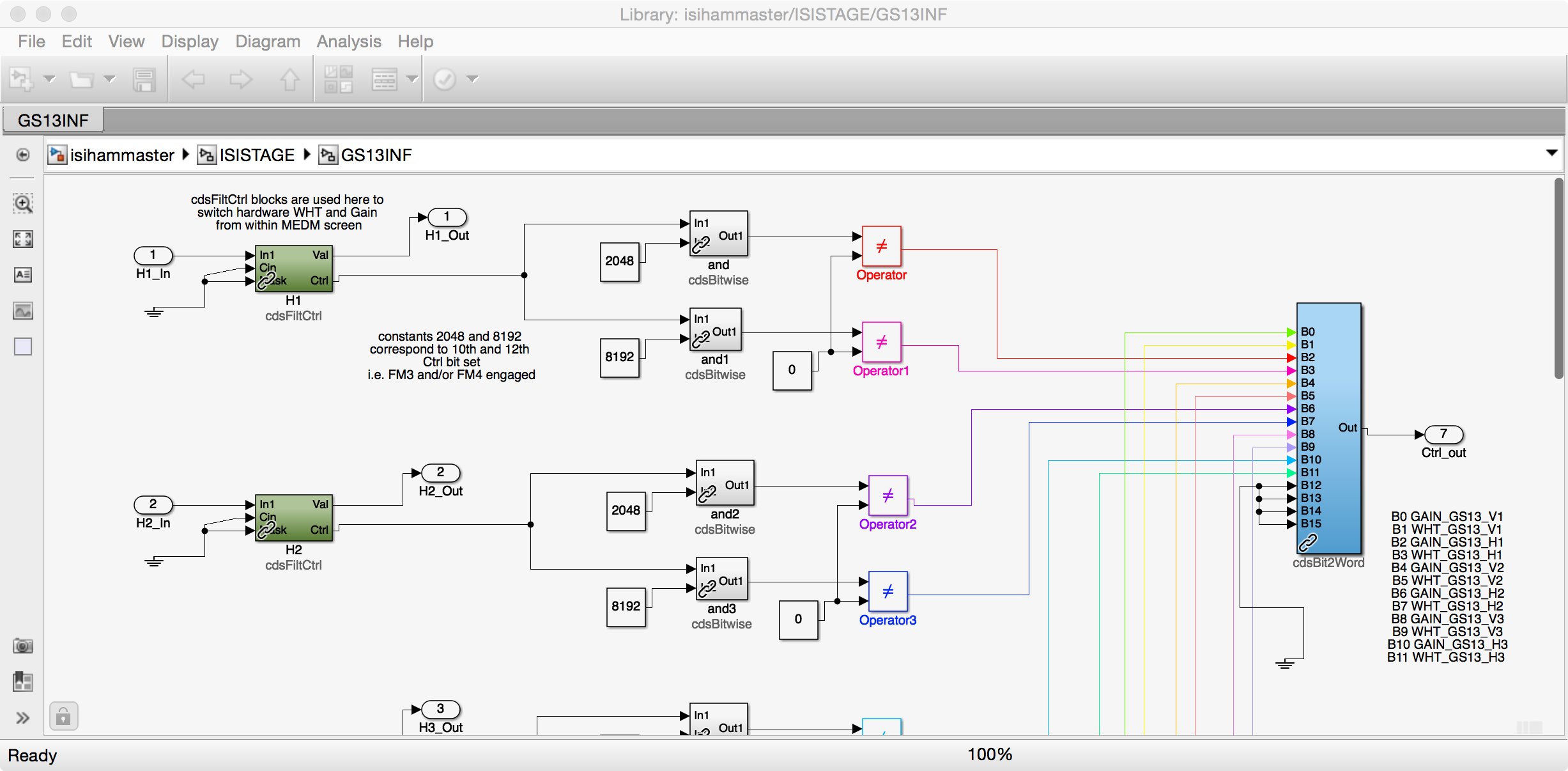
WP 7749 (Add GS13INF..._OUT to Frames) FRS 11049 (HAM2 & 3 GS13 Gain Switching failure)
I've only looked at the first switch failure closely but I have many more in the can (just ask the operator JeffB) now with the model change adding the GS13INF_.._OUT channels to the frames.
My theory at the moment looking at the first trip is that the corner 2 & corner 3 switching is cross wired. I don't know where yet as that mapping is complex--working on it. Meanwhile...
Look at the attachment and listen to my story...
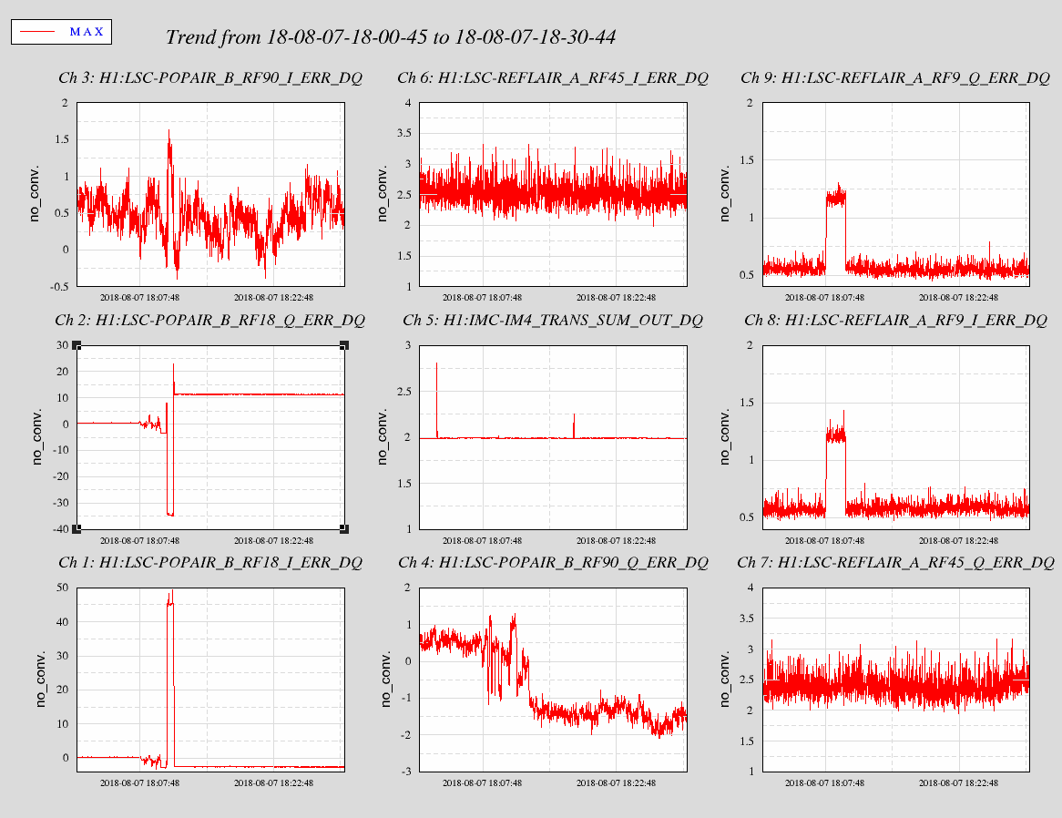
After getting the GS13INF_OUTs into the frame, I put the platforms into nominal ISOLATED state except the GS13s were in the low gain mode. I manually toggled off every filter for the GS13 gain state and noted the success of the switch. For HAM4, every filter switched with out bothering the platform. On HAMs 2 & 3, corner 1 H & V all switched with out bothering the platform. Conversely, on HAMs 2 & 3, corners 2 & 3 both H & V, every switch of FM 4 or 5 tripped the platform. I did not repeat every switch because the trips took time to recover, and, trips of the verticals on the ISI also tripped the SUSs on board. However, every repeat yielded the same result as noted, there was no inconsistent result. So I zoom into the first trip when I toggled the DW filter on HAM2 H2:
1/2 second of data displayed. Note the H2 (corner 2) SWSTAT change as the FM5 Dewhitening filter changes state. So you can see that the H2 signal (upper left green) gets more high frequency noise even compared to before the switch when the analog whitening is on and its digital DW filter is on; so the digital DW goes away but the analog whitening is still on. Conversely, looking at the H3 GS13 signal (lower right,) the analog & digital whitening and dewhitening filters are on and then the analog whitening is disabled and the digital dewhitening remains on and the signal gets very clean. Note that the H1 GS13 signal is unaffected.
So, bottom line, current theory: corner 2 digital filter is wired to corner 3 analog filter.
Why it could be happening. Maybe best bet is the problem where long long ago, the PSL group asks SEI/ISI to change feedthrus on the chamber because cables they had would not reach the flange. Normally on the ISI, corners 1 & 2 are near each other because the first CPS satellite crate has room for two corners ( there is not a separate crate for each corner on the HAMs.) When SEI changed to a different chamber feedthru, ISI cable length limits necessitated putting corners 1 & 3 into the same CPS satellite crate. We wanted all a corner's channels to go to the same feedthru so GS13 and coil drivers cables were also moved (see SEISMIC REFERENCE note on D1002873.) Since the CPS channels from a crate are on the same cable, corners 1 & 3 go into the same Interface chassis and hence the model must reflect this difference. It is around here that I suspect the problem.
The python command scripts must manage to most of the time switch the corners 2 & 3 quickly enough that it seems to work, usually. The guardian scripts however must do it just enough more slowly that it blows up.
I'll look at the other switches done and see if this story all holds up.
I hope this is the problem.
This can be easily checked by manually switching just one filter at a time.
Switching the Gain or Whitening filters from the GS13_INF filters can be done manually. The engagement of the filter module is the event which switches the digital BIO. I've attached a bit of the GS13INF module from the HAM control diagram to show this.
Thanks Brian--Yes, switching the filters manually is how I tested this: " I manually toggled off every filter for the GS13 gain [& whitening] state and noted the success of the switch."
I'm not sure if the BIO readback is helpful tho as if the model & hardware are cross-wired, the medms will suggest a correct switch. There might be some monitor on the BIO chassis we could pick off otherwise a thorough comb through the model and wiring is in order.
Herein however is the second instance that I again state is very good indication of the miss-wiredness: Attached is ~1/2 second of full data where now the digital gain (FM4) is turned off on the corner 2 horizontal GS13 and we see the H3 output blow up while the H2 signal goes quiet w/o its compensating analog gain. Least one be wary about the signals being fouled by the platform trip, look at the H1 signal where there is a clear gap between H2 & H3 changes and when the platform really starts its throes of death.
Okay--EE, CDS, & LHO SEI believe we know what the problem is and a relatively straight forward and easy way to fix this.
1) LHO GS13 Field wiring does not match the drawing. When we put CPS corners 1 & 3 together for the aforementioned PSL FT need, we thought it made sense to put the GS13s in a similar pairing--this does not match the HAM2 & 3 ISI wiring, D1101576.
2) LHO GS13 BIO switching wiring does match the drawing and this combined with 1) yields the poor results:
The GS13s 1 & 3 (Corners) are wired correctly into the top level model such that Cartesian conversion & Isolation of the platform does work. The Binary switching begins in the Common model and works upward into the top level but given hardware constraints (multiple channel switching on single cable) is unable to swap channels 2 & 3.
So, the binary switching going to Interface chassis one thinks it is switching corners 1 & 2 GS13s but GS13s 1 & 3 are on that chassis hence our digital analog miss-wire and poor behavior on corners 2 & 3.
At one time, it was likely that we had different models for HAMs 2 & 3 addressing this but no longer.
Fortunately the fix is relative simple: a) Switch the field cables at the Interface chassis for GS13s corners 2 & 3--they will then reflect the drawing (and match LLO.) b) Rewire the top level model to reflect this wiring change. Then the binary switching will actually be talking to the correct sensor.
Here is an examination into a couple of the HAM3 GS13 switches showing the same behavior as above.
First, overall plot shows that when switching H1, no evidence of the switch seen on the _OUT signals, how it is supposed to be. Not so much when the H2 filter is switched.
Second plot, shows the switching off of the digital DeWhitening on H2 and the affect on the H2 & H3 signals.
Third plot shows similar when the H2 digital Gain is toggled off and H2 goes quiet and the H3 signal blows up. Same as HAM2.
Lesson learned--check the wiring!
Dick, Marc, Nolan Replaced 6 baluns in ISC Racks R1 and R2. The insertion loss and phase shift through each balun was measured prior to installation, and compared to the phase shift through removed balun. Serial numbers, locations, bode plots and phase differences for each are annotated in the attached file (Doc and PDF formats). Noise measurements are attached, with most recent measurement (Aug 7, 2018) after replacement of final 6 baluns in green.
[Hang, Gabriele]
We noticed that some of the signals (in particular LSC-POPAIR_B_RF18 and LSC-POPAIR_B_RF90) got different offsets. We put the IMC offline and retuned the dark offsets.
H1:LSC-TR_X_QPD_B_SUM_OFFSET and H1:LSC-TR_Y_QPD_B_SUM_OFFSET had to be tuned manually, since the script was not accurate enough (or did the wrong things, we did not investigate further)
Hi Hang and Gabriele, I was looking at the offset timeseries for this change, and it seems that the offset got larger after the balun change. Is this what you see too? I would have hoped that offsets get smaller if the ambient static RF field is reduced. Nothing is obvious in this stuff.
Actually, the offsets changed only slightly. See plot below.
Due to some lower limits of the RTL-SDR RF antenna, only the 27 MHz and the 45 MHz "before and after" RF scans came out correctly. With the improved balun the 27 MHz leakage is significantly better. The 45 MHz leakage appears to be slightly worse... I second Rich's claim that "nothing is obvious in this stuff."