<b>TITLE:</b> 08/03 Day Shift: 15:00-23:00 UTC (08:00-16:00 PST), all times posted in UTC
<b>STATE of H1:</b> Commissioning
<b>INCOMING OPERATOR:</b> None
<b>SHIFT SUMMARY:</b>
<b>LOG:</b>
15:08 Karen out to EY
15:15 Chandra out to MX fr Soft close of GV15
16:00 Karen out to EY to bring garb
16:05 Hugh out to EX
16:13 Kyle out to EX
16:43 Hugh back
16:49 Travis and Niko out to EY - PCal
17:04 IMC issues seem to be resolved-for the moment
17:30 Corey out to the LVEA
17:40 Haocun out to LVEA- SQZ table
17:42 Hugh and Indian visitor going out to LVEA
17:56 Corey back
17:57 Aiden and TJ back from EX
18:00 Hugh and guest back
18:07 Gerardo, Jess, Davis and Jeff out to LVEA - WP#7752
18:20 TJ and Aiden out to EY
18:21 Danny out EX
18:45 TJ and Aiden back and the to EX
18:59 Jason ad Indian guest out tot PSL enclosure
19:02 Model/DAQ restarts before running charge measurements
19:06 Gerardo, Jess, David, and Jeff back
19:13 Charge measurements started on ETMX
19:20 Charge measurement restarted
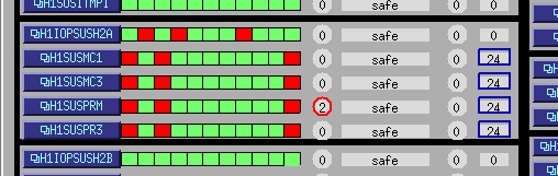
19:25 IMC computer crashed again
19:30 Kyle back
20:09 Robert and co. out to EX to pick up some equip
20:10 Jeff K ad Dave out to CER to investigate computer crash
20:15 Jason and guest back
20:40 after the most recent model/daq restart (following timing crash) Jeff and I have reset slider values back to 10 hours ago
20:42 Haocun out to LVEA
21:00 Sensor correction turned of at EX for the PCal team
21:35 TJ back
21:38 Chandra and guest to EY for a tour
22:17 Chandra, Arun, and Mike into LVEA
22:23 Niko and Travis back
[Aidan, Danny, TJ]
The ETMX HWS was missing a couple of M3 x 6mm screws necessary to clamp the front plate (D1000658) to the spacer plate (D1000708). Since we wanted to finish testing the ETMX HWS, we transferred the Hartmann plate assembly (D1000658, D1000708 and D1000669) from ETMY to ETMX.
We are currently short a complete assembly on ETMY now. The acquisition of some metric hardware will fix this though.
Sheila, Dave:
we installed a new h1ascimc model, adding power normalization. DAQ was restarted
+: slow channel H1:ASC-I_SUM_NORM added to the DAQ
+: slow channel H1:ASC-I_SUM_POW_NORM added to the DAQ
+: slow channel H1:ASC-Q_SUM_NORM added to the DAQ
+: slow channel H1:ASC-Q_SUM_POW_NORM added to the DAQ
Daniel made a new h1sqz model, it was restarted at 13:47PDT. No DAQ restart was needed (internal wiring was changed)
Ed, Jeff, Fil, Dave:
I'm not sure if this is a coincidence, but the h1iopsush2a IRIG-B excursion had almost completed its recovery (after almost 3 hours) when the IOP glitched again. The IRIG-B had gone up to about 1500 and was down at 75 at the time of the glitch (24 is the start of the good range).
This time all user models showed an FE error (see attachment).
I stopped all the models and ran h1iopsush2a by itself, verifying there was not an IRIG-B error.
As an unconnected problem, I noticed that the second 18bit DAC AI chassis was reporting an ON status even though the IOP was commanding all AI's to be OFF (see attachment). Jeff verified the AI rack locations, and it was found that the second 8-channel block of the AI was permanently ON, even with the DAC cable disconnected from the rear. Fil replaced the AI chassis with a spare, the switching function has been restored.
Around this time h1sush2b glitched. Its models were restarted with no problems.
I restarted the remaining models on h1sush2a (h1susmc[1,3], h1suspr[m,3]).
Attached plot shows a 6 hour minute trend of h1iopsush2a's IRIG-B value (red) and its STATE_WORD (black). It can been seen that the STATE_WORD is in its good state (value=0) for most of the IRIG_B excursion, and fails close to its end.
Failure of h1sush2a is associated with FRS Ticket 11222. Identification and fix of AI chassis is associated with FRS Ticket 11223.
AI chassis S1108081 replaced with S1104370.
Corner station RGA scan attached. N2 peak is high. We will monitor to see how it decreases with time. SEM voltage set to 1300V.
Corner station pressure trend attached. Notice the flat trend followed by an obvious change in slope.
Corner station RGA scan this morning. H2, H2O, N2 levels are about the same from 10 days ago.
Marissa Walker, Josh Smith, Alex Macedo, Oli Patane We looked at recent data to see if we could measure new violin mode frequencies. We used the DRMI 3f lock stretch mentioned in this alog . We made long (~10mHz frequency resolution) spectra of H1:LSC-DARM_IN1_DQ (Figure 1) and many ALS channels, but the violin modes were not clearly visible in any of them. We also measured spectra during a longer time from Aug 3rd (1217291534.25 to 1217297671.19) when there was ALS DIFF data but not DRMI, but again no violin modes were visible. So it seems, if we’ve chosen channels wisely, that the sensitivity is not yet sufficient to spot the new violin modes. We will continue to look at data as we get longer times and better sensitivity.
@DetChar -- thanks for the quick turn-around! Have you tried ALS COMM channels while Craig was measuring the COMM noise performance (see LHO aLOG 43214)? You can gather the time and channel to use from his DTT screenshot, and it looks like he used 10 averages for a 0.01 Hz bin-width data, so that should mean you can at least get 5 mHz resolution with 5 averages... Also, have you tried the looking through AS WFS?
Thanks for the suggestion, Jeff! I talked with Craig to get the time and channels, and made a higher resolution spectrum of the COMM noise from the same time, but still don't see the violin modes. https://ldvw.ligo.caltech.edu/ldvw/view?act=getImg&imgId=194662
Sheila and I saw violin modes in DARM starting at around 04/08/2018 6:10:00 UTC today.
Sheila, Dave:
A new h1ascimc model was started with a new DAQ configuration:
+: fast channel H1:ASC-AS_A_RF45_I_SUM_OUT_DQ added to the DAQ
+: fast channel H1:ASC-AS_A_RF45_Q_SUM_OUT_DQ added to the DAQ
the DAQ was restarted.
This reminded me of the RCG3.2.3 work I had done on h1pemmx some time ago. It was a test system for the RCG3.2.3 upgrade of the SUS-QUAD models. Both its models and its mx_stream had been upgraded to 3.2.3 to show that the DAQ error could be cleared if the new mx_stream is ran. After the DAQ was restarted it was left running 3.2.3 models and 3.2 mx_stream (like the SUS-QUADs are). I recompiled h1ioppemmx and h1pemmx using rcg3.2 and restarted them, clearing the DAQ error on these models.
While the PIT and YAW signals from the ASC WFS are normalised, the SUM is not. We have modified the channels for ASC_AS_A_RF45_I and Q SUM the to include power normalisation.
The h1ascimc model was re-restarted to incorporate these changes.
Around 08:30 PDT h1iopsush2a had an ADC-DAC timing glitch. Pressing DIAG_RESET cleared the ADC error, but the glitch was large enough to desynchronize the DAC channels and the IOP went into its safe state of not driving any DAC channels.
At 09:24 I did a simple stop-all-models, start-all-models restart. Within 5 minutes the IOP glitched again. /proc/h1iopsush2a/status showed a large ADC timeout of 180uS at 09:34.
At 09:48 I performed a full power cycle of the cpu and IO Chassis. Sequence was: stop-all-models, take node out of Dolphin fabric, power down cpu, power down IO Chassis*, power up IO Chassis (wait for good timing lock), power up cpu (autostarts models).
* before powering the IO Chassis down, I noted it had a good timing status on the timing slave card.
This time the IOP IRIG-B went into a positive excursion, it had topped out at 1500 and is on its way down. System has been running for 25 minutes with no repeat of the ADC-DAC timing issues.
I noted that the auto-calibration of the 18bit DACS are all good, but the third card consistently takes longer to calibrate:
controls@h1sush2a ~ 0$ dmesg|grep CAL
[ 50.143460] h1iopsush2a: DAC AUTOCAL SUCCESS in 5341 milliseconds
[ 55.506760] h1iopsush2a: DAC AUTOCAL SUCCESS in 5344 milliseconds
[ 62.536318] h1iopsush2a: DAC AUTOCAL SUCCESS in 6572 milliseconds
[ 67.899590] h1iopsush2a: DAC AUTOCAL SUCCESS in 5345 milliseconds
[ 73.693450] h1iopsush2a: DAC AUTOCAL SUCCESS in 5344 milliseconds
[ 79.056792] h1iopsush2a: DAC AUTOCAL SUCCESS in 5345 milliseconds
[ 84.425154] h1iopsush2a: DAC AUTOCAL SUCCESS in 5345 milliseconds
Failure of h1sush2a is associated with FRS Ticket 11222.
Throttled GV15 by running the gate down for 4 min. 15 sec. (not quite soft closed) to block the laser beam from reaching EX for commissioning activities. Will reopen around noon or when commissioners inform VAC team they are ready.
GV15 is opened back up.
Sheila, Craig We retook the ALS COMM frequency noise measurement using the IR PDH signal of REFL_9_I at an out-of-loop witness. In my old measurement, I hadn't removed the 42 Hz IR arm pole from the spectrum. This time it's removed using a DTT calibration filter which is just a zero at 42 Hz. This time we requested 10 watts input power while resting on the fringe to try and suppress REFL_9 sensor noise, and we were successful.
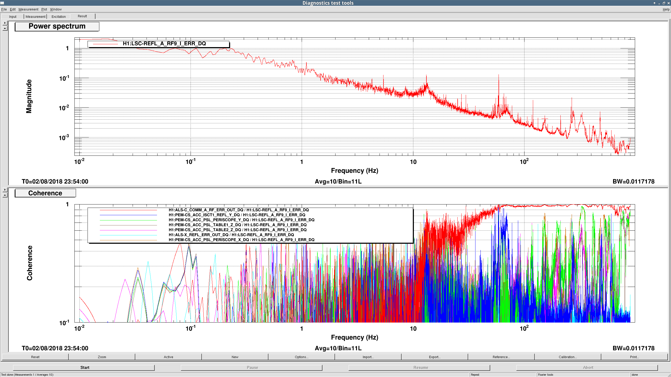
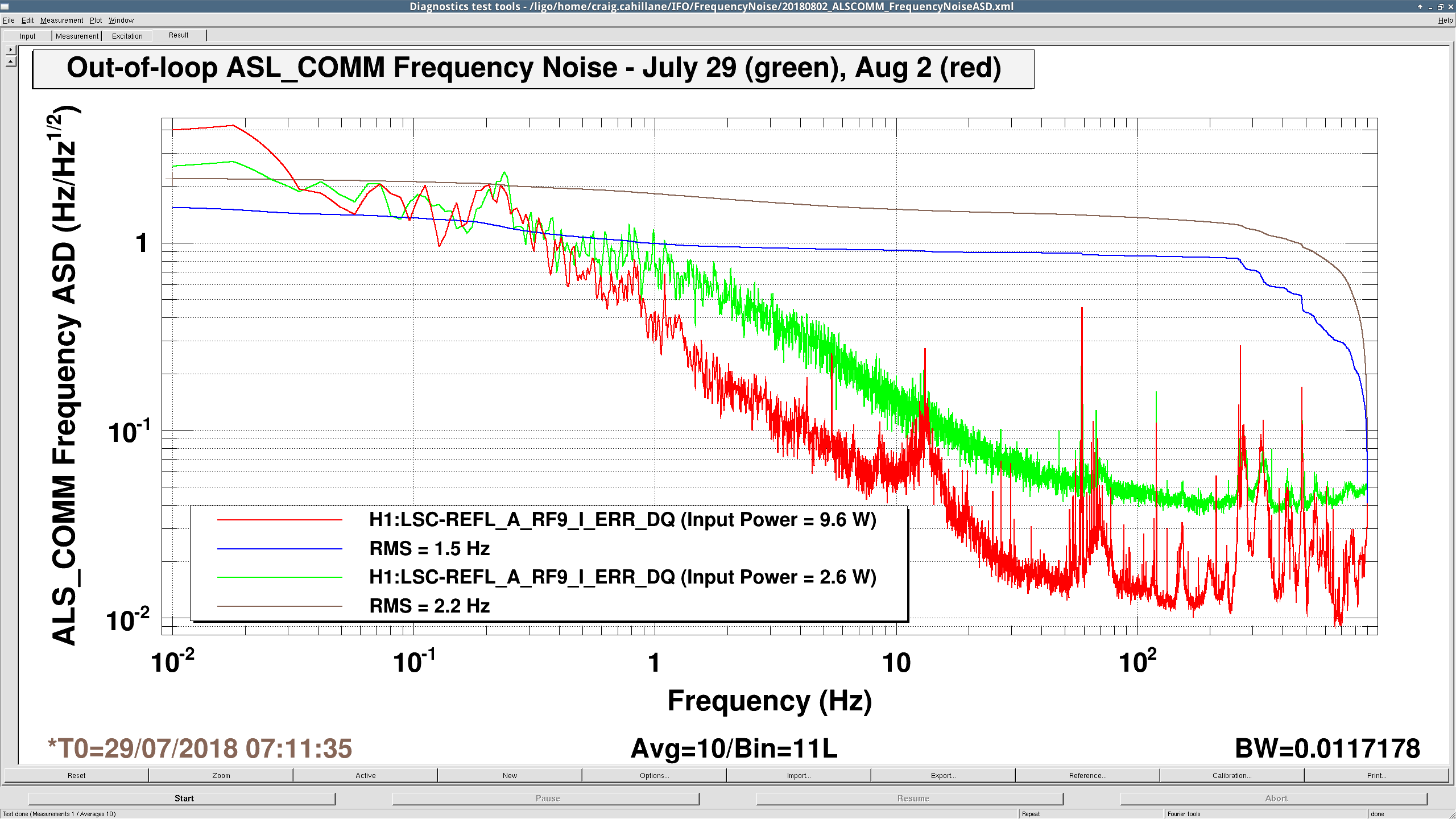
Out-of-loop ALS_COMM Frequency Noise RMS = 1.5 Hz
Measured Input Power August 2 = 9.6 W Measured Input Power July 29 = 2.6 W REFL_9_I_ERR_DQ Calibration August 2 = 2.0 Hz/cts REFL_9_I_ERR_DQ Calibration July 29 = 18.0 Hz/ctsIt seems our broadband suppression above 1 Hz goes linearly with power, which suggests we're limited by dark noise. More investigation of the REFL_9 signal chain required. I was only able to integrate RMS starting at 900 Hz since we used the REFL_9_I_ERR_DQ channel this time. Still unclear what's happening above 1 kHz, probably REFL_9 noise was killing our measurement there as well, but it could also be COMM sensor noise starting to take over.
Comparing the noise to Class. Quantum Grav. 31 (2014) 245010, one can see that the noise is significancy lower. From the new ETMs with the corrected green transmission we expected a factor of ~5 reduction of the end station noise. This includes the PDH sensing noise of the green locking (curve VI), the fiber noise (VII) and the laser noise (VIII). We still expect a contribution of about 2 Hz rms from these, concentrated at frequencies near 1 kHz.
The surprise is that the noise due to acoustic (curve V) and fringe wrapping (III) is also much lower. We didn't notice this in the past with the higher noise coming from the end stations. I suspect this is due to improvements in the acoustic couplings we made around the PSL. The early ALS measurements were done before we recognized its importance.
The above plot also misses the VCO noise which contributes another ~2Hz at frequencies below 0.01 Hz. This would indicate that the new common ALS noise is around 3-4 Hz rms. This is almost an order of magnitude better than the original ALS system.
PEM seems to explain some of the peaks we're seeing in the 10 watt input power ALS COMM spectrum. The periscope accelerometers is strongly coherent with a bunch of high frequency peaks (330 Hz, 154 Hz, 200 Hz, mess above 500 Hz). The ISCT1 accelerometer is coherent with the broad peak around 70 Hz.
This afternoon,
- I wiped the AERM and ETM barrel surfaces as best I could with swabs and methanol to remove particulate.
- Travis and I removed the FirstContact sheet from the optic - upon inspection, we still found some point features within the central ~6" of the optic HR surface. They did not blow away with 20psi N2 Top Gun, nor do they look like FC pieces. I will compare my pictures to the map we made during last year's lab inspection.
- Travis and I checked for charge via the "normal" procedure of looking with an electrometer at the back surface of the AERM with a special bracket. Details below to follow.
- Travis ocked all EQ stops nuts, taking into account sag once under vacuum.
- We set the top 4 QUAD BOSEMs to slightly more closed, also to take into account the sag of the suspensions once under vacuum.
- Removed all tooling, wiped floor and ACB surface.
- Travis swung the ACB back into it's nominal position.
- Jim unlocked the ISI and made a quick medm check.
- Laid new witness CC wafers and optics. - Pulled FC from 2x optics (1 vertical on QUAD, 1 horizontal under QUAD).
Tomorrow we will run TFs in the am and then launch the door crew.
Forgot to mention that just after the FirstContact pull, we installed the electrometer bracket to the back side of the AERM and measured in the Center, and 4 quadrants charge on the electrometer between +/-3V. Data to follow.
Finally getting around to putting in the actual numbers for these measurements taken on May 31, 2018 at 3:30pm. This Quad now has an AERM in the reaction chain.
Procedure: Pulled First Contact, blew all surface and the gap for 60 seconds. Took electrometer readings at 5 locations. UL = -3.1 V, UR = -3.3 V, Center = 3.4 V, LR = 0.1 V, LL = 3.8 V.
Tested electrometer fluctuations by putting the cap on the electrometer head and setting it on the floor of the chamber (no person touching it) and zeroed it. Reading fluctuated betwee 0 and 3 V.
Measured all 5 locations again 10 minutes after the first blow. UL = 2.5 V, UR = 2.0 V, Center = 3.0 V, LR = 2.0 V, LL = 2.0 V.
One more h1ascimc restart to correct channel names, with associated DAQ restart