Displaying reports 46261-46280 of 88222.Go to page Start 2310 2311 2312 2313 2314 2315 2316 2317 2318 End
Reports until 11:39, Friday 03 August 2018
H1 ISC
gabriele.vajente@LIGO.ORG - posted 11:39, Friday 03 August 2018 (43228)
REFL WFS phasing

In DRMI without the arms, REFL_A and REFL_B phases are fine, both 9MHz and 45MHz.


Images attached to this report
H1 PSL
thomas.shaffer@LIGO.ORG - posted 11:20, Friday 03 August 2018 (43227)
Added 250mL to Crystal Chiller

I heard a chiller alarming while I was passing through receiving. Added 250mL to the crystal chiller. This is worrying since someone added 100mL yesterday. Ed checked the relative humidity and it spiked 4 hrs ago. The PSL team as been informed.

H1 General
jeffrey.bartlett@LIGO.ORG - posted 11:04, Friday 03 August 2018 (43226)
ITM Optics Photos - No green light

   With the green light shuttered (gate valves shut) took the opportunity to take a few shots of ITM-X and ITM-Y. The objective of these photos was to understand how the ITM OpLevs light pollutes the images of the ITM optics. When these shots were taken, there was a little 1064nm light present, which is visible as the purple areas on the optics. There is a small amount of OpLev light on the ITM optics from the up and down stream OpLevs. This light does not represent an issue for ITM optics face photos.

   These photos demonstrate the ITM OpLevs will need to be switched off to get good images of the entire optic face. Need to repeat this study with stronger 1064nm light on the optic to see if it can dominate over the OpLev scatter.

ITM Optics - No green light
Arm Frame Exposure Focus OpLev-X OpLev-Y Notes
ITM-Y Y-F1 3.0 sec #2 - 65 On On OpLev light pollution dominates upper left of optic.
  Y-F2 3.0 sec #2 - 65 On Off Still some light pollution from OpLev X.
  Y-F3 10.0 sec #2 - 75 Off Off Increase exposure to replace OpLev light - Seeing some spots on the optic.
  Y-F3 10.0 sec #2 - 85 Off Off Tighter focus - See spots left edge to bottom - Some spots near center.
             
ITM-X X-F1 3.0 sec #1 - 1755 On On OpLev light pollution dominates upper right of optic.
  X-F2 3.0 sec #1 - 1755 Off On Still some light pollution from OpLev Y.
  X-F3 6.0 sec #1 - 1755 Off Off Under exposed - Some IR visible in upper left. - Some OpLev light lower right.
  X-F4 30.0 sec #1 - 1755 Off Off Longer exposure - Some light from other OpLevs - No surface spots visible.


Images attached to this report
H1 TCS (AWC, TCS)
thomas.vo@LIGO.ORG - posted 10:35, Friday 03 August 2018 (43223)
ITMX CO2X First Look

[TCS Team]

The CO2X laser tripped last night before we could not inject some heating for a couple minutes.  However, the pre-heating guardian for CO2X was turned on for about 3 hours at 500 milliwatts with central heating so we can get some preliminary information about the centering.

This is the heating up:

This is the cool down:

There doesn't seem to be any apparent clipping/fringing of the CO2 beam, and centering isn't terrible.  The edge on the upper right side is due to clipping of the HWS beam.

Images attached to this report
H1 CDS
david.barker@LIGO.ORG - posted 10:21, Friday 03 August 2018 - last comment - 14:55, Friday 03 August 2018(43225)
h1sush2a timing issues

Around 08:30 PDT h1iopsush2a had an ADC-DAC timing glitch. Pressing DIAG_RESET cleared the ADC error, but the glitch was large enough to desynchronize the DAC channels and the IOP went into its safe state of not driving any DAC channels.

At 09:24 I did a simple stop-all-models, start-all-models restart. Within 5 minutes the IOP glitched again. /proc/h1iopsush2a/status showed a large ADC timeout of 180uS at 09:34.

At 09:48 I performed a full power cycle of the cpu and IO Chassis. Sequence was: stop-all-models, take node out of Dolphin fabric, power down cpu, power down IO Chassis*, power up IO Chassis (wait for good timing lock), power up cpu (autostarts models).

* before powering the IO Chassis down, I noted it had a good timing status on the timing slave card.

This time the IOP IRIG-B went into a positive excursion, it had topped out at 1500 and is on its way down. System has been running for 25 minutes with no repeat of the ADC-DAC timing issues.

I noted that the auto-calibration of the 18bit DACS are all good, but the third card consistently takes longer to calibrate:

controls@h1sush2a ~ 0$ dmesg|grep CAL
[   50.143460] h1iopsush2a: DAC AUTOCAL SUCCESS in 5341 milliseconds
[   55.506760] h1iopsush2a: DAC AUTOCAL SUCCESS in 5344 milliseconds
[   62.536318] h1iopsush2a: DAC AUTOCAL SUCCESS in 6572 milliseconds
[   67.899590] h1iopsush2a: DAC AUTOCAL SUCCESS in 5345 milliseconds
[   73.693450] h1iopsush2a: DAC AUTOCAL SUCCESS in 5344 milliseconds
[   79.056792] h1iopsush2a: DAC AUTOCAL SUCCESS in 5345 milliseconds
[   84.425154] h1iopsush2a: DAC AUTOCAL SUCCESS in 5345 milliseconds


Comments related to this report
jeffrey.kissel@LIGO.ORG - 14:55, Friday 03 August 2018 (43242)CDS, DAQ, FRS, SUS
Failure of h1sush2a is associated with FRS Ticket 11222.
H1 PSL
peter.king@LIGO.ORG - posted 09:19, Friday 03 August 2018 (43221)
PMC servo work
This morning I installed the modified pre-modecleaner servo.  In short, I could not lock the pre-modecleaner with it.

    The difference between the modified board and the in-service one, is the addition of two active notches to notch
out the pre-modecleaner PZT resonances.  The phase delay switches were changed to DDDDDDUUU to restore the sign of the
error signal.  Despite what I think is the correct feedback sign, I could not get the pre-modecleaner to lock.  The
(original) in-service pre-modecleaner was re-installed, along with restoration of the phase delay switch settings in
order not to delay commissioning work for this morning.

    Back to the EE Lab with this one.
H1 General (IOO)
edmond.merilh@LIGO.ORG - posted 09:03, Friday 03 August 2018 - last comment - 09:24, Friday 03 August 2018(43220)
IMC crashed

At ~15:28 the IMC suffered a DAC and DK error causing OSEM values in MC1 and MC3 to change drastically. Slider values have not changed. WFS history was cleared. The Drift_Mon panel on the right (in the figure below) is from 2 hours prior. The diag reset function on the CDS overview reset the DAC error but it seems that some models and computers need to be restarted. Currently I'm waiting or Dave Barker to arrive.

Images attached to this report
Comments related to this report
edmond.merilh@LIGO.ORG - 09:24, Friday 03 August 2018 (43222)

16:23 Dave Barker onsite. I brought MC1, MC3, PRM, and PR3 to safe for model restart.

LHO VE
chandra.romel@LIGO.ORG - posted 08:40, Friday 03 August 2018 - last comment - 13:04, Friday 03 August 2018(43219)
throttled GV15 at MX

Throttled GV15 by running the gate down for 4 min. 15 sec. (not quite soft closed) to block the laser beam from reaching EX for commissioning activities. Will reopen around noon or when commissioners inform VAC team they are ready.

Comments related to this report
chandra.romel@LIGO.ORG - 13:04, Friday 03 August 2018 (43230)

GV15 is opened back up.

H1 General
edmond.merilh@LIGO.ORG - posted 08:07, Friday 03 August 2018 (43217)
Shift Transition - Day

TITLE: 08/03 Day Shift: 15:00-23:00 UTC (08:00-16:00 PST), all times posted in UTC
STATE of H1: Commissioning
OUTGOING OPERATOR: None
CURRENT ENVIRONMENT:
    Wind: 18mph Gusts, 15mph 5min avg
    Primary useism: 0.04 μm/s
    Secondary useism: 0.06 μm/s
QUICK SUMMARY:


H1 ISC (ISC)
georgia.mansell@LIGO.ORG - posted 22:04, Thursday 02 August 2018 - last comment - 22:11, Thursday 02 August 2018(43215)
Towards reduce_carm_offset

Sheila Craig Georgia Hang

This evening we continued trying to improve the CARM handover from ALS-COMM to LSC-TR, following on from last night's work (alog-43190).

We fixed an error where the LSC-RELFBIAS input matrix elements were left on, and now the the arm transmissions (LSC-TR_X and Y) are much quieter at the CARM_TO_TR step. We retook the TR_CARM open loop transfer function which looks better than yesterday. We tried skipping the step added yesterday which brought the arms to a 100Hz offset in the PREP_TR_CARM before handing over, but found this step was necessary to find the IR.

We went to the next guardian state: REDUCE_CARM_OFFSET, and could not maintain this for very long before losing lock (after ~1 minute).

We tried to get to the DARM_TO_RF state but found the ETMX HEPI tripped, it looks like there might be a timing error as the watchdog trips before the tidal monitor saturates. The sensor in this stage of locking is ASC-AS_A_RF45_Q_SUM_OUT16, which is not a DQ channel, it would be handy to store this channel so we can look back at the locklosses.

Comments related to this report
sheila.dwyer@LIGO.ORG - 22:11, Thursday 02 August 2018 (43216)

Here is a plot of some of the channels that caused HEPI to trip when we tried the transition to RF DARM.  The second plot is zoomed in in time around the lockloss, and shows that the timing is confusing.  It should be that the first thing that happens is the large impulse in DARM (because we tried to transition to an error signal that wasn't good), then a low passed version of this should show up in tidal channels, and an even more low passed version shoud show up in the HEPI channels.  Instead it seems that the signal shows up in HEPI first. 

Images attached to this comment
H1 ISC (ISC)
craig.cahillane@LIGO.ORG - posted 19:11, Thursday 02 August 2018 - last comment - 15:29, Friday 03 August 2018(43214)
Out of Loop ALS COMM frequency measurement - Take Two
Sheila, Craig

We retook the ALS COMM frequency noise measurement using the IR PDH signal of REFL_9_I at an out-of-loop witness.  In my old measurement, I hadn't removed the 42 Hz IR arm pole from the spectrum.  This time it's removed using a DTT calibration filter which is just a zero at 42 Hz.

This time we requested 10 watts input power while resting on the fringe to try and suppress REFL_9 sensor noise, and we were successful.


Out-of-loop ALS_COMM Frequency Noise RMS = 1.5 Hz

Measured Input Power August 2 = 9.6 W
Measured Input Power July 29  = 2.6 W
REFL_9_I_ERR_DQ Calibration August 2 =  2.0 Hz/cts
REFL_9_I_ERR_DQ Calibration July 29  = 18.0 Hz/cts 

It seems our broadband suppression above 1 Hz goes linearly with power, which suggests we're limited by dark noise.  More investigation of the REFL_9 signal chain required.

I was only able to integrate RMS starting at 900 Hz since we used the REFL_9_I_ERR_DQ channel this time.  Still unclear what's happening above 1 kHz, probably REFL_9 noise was killing our measurement there as well, but it could also be COMM sensor noise starting to take over.
Images attached to this report
Non-image files attached to this report
Comments related to this report
daniel.sigg@LIGO.ORG - 10:15, Friday 03 August 2018 (43224)

Comparing the noise to Class. Quantum Grav. 31 (2014) 245010, one can see that the noise is significancy lower. From the new ETMs with the corrected green transmission we expected a factor of ~5 reduction of the end station noise. This includes the PDH sensing noise of the green locking (curve VI), the fiber noise (VII) and the laser noise (VIII). We still expect a contribution of about 2 Hz rms from these, concentrated at frequencies near 1 kHz.

The surprise is that the noise due to acoustic (curve V) and fringe wrapping (III) is also much lower. We didn't notice this in the past with the higher noise coming from the end stations. I suspect this is due to improvements in the acoustic couplings we made around the PSL. The early ALS measurements were done before we recognized its importance.

The above plot also misses the VCO noise which contributes another ~2Hz at frequencies below 0.01 Hz. This would indicate that the new common ALS noise is around 3-4 Hz rms. This is almost an order of magnitude better than the original ALS system.


craig.cahillane@LIGO.ORG - 15:29, Friday 03 August 2018 (43243)
PEM seems to explain some of the peaks we're seeing in the 10 watt input power ALS COMM spectrum.

The periscope accelerometers is strongly coherent with a bunch of high frequency peaks (330 Hz, 154 Hz, 200 Hz, mess above 500 Hz).
The ISCT1 accelerometer is coherent with the broad peak around 70 Hz.
Images attached to this comment
H1 SEI (DetChar, SYS)
jeffrey.kissel@LIGO.ORG - posted 17:16, Thursday 02 August 2018 (43213)
BLRMS Time Series of EX and EY Ground Motion vs. Wind
J. Kissel

John Zweizig has recently and graciously added the beam rotation sensor (BRS) and ground super sensor channels to the DMT Monitor Tool set, so I wanted to play around and imagine what a future wall FOM might look like. Attached are screenshots of what I'm imagining.

On a science note -- it really is impressive to see the BRS subtraction at work. Under the 20-30 miles/hour winds we had yesterday evening (22-24 hours ago), we can see around an order of magnitude subtraction in the 0.03-0.1 Hz band. One can also see the the earthquake we had 2 hours ago is nicely resolved after subtracting the ~20 mph wind-caused rotation.

It's a new era! I'd love to see similar plots at LLO...

The templates live (for the time being) here:
    /ligo/home/jeffrey.kissel/Templates/DMTViewer/
        GND_BLRMS_EndStations_0p03to0p1Hz.xml
        GND_BLRMS_EndStations_0p1to0p2Hz.xml
I'm waiting for the addition of wind channels directly into the monitor before I'll say they're reday for prime time and to be moved to somewhere where they can be displayed on the wall.
Images attached to this report
H1 TCS (TCS)
aidan.brooks@LIGO.ORG - posted 16:22, Thursday 02 August 2018 (43208)
ETMX HWS source alignment and mode-matching work - 50um core fiber produces a cleaner mode

[Aidan, TJ, Danny]

Summary

We injected the HWS LED source and got a return beam from ETMX.

Details

Yesterday, the beam on the ETM HWS optics was quite large and couldn't be brought to a tight focus. I figured we'd get a cleaner (but less intense) beam with a smaller core fiber. So we swapped out the 200um 0.22NA core fiber for a 50um 0.22NA core fiber this morning. This allowed us to bring the beam to a much tighter focus around the first imaging lens (as required by the mode-matching solution).

  1. We aligned two irises to the HWS LED beam in the HWS optical path
  2. We ran the beam through the horizontal polarizer and injected it into the PBS.
  3. We then aligned that transmission to the two ALS irises.
  4. When we failed to get any reflection from the ETM, we turned on the ALS beam and adjusted the alignment of the two picomotor mirrors (manually, not with motors) so that the ALS beam returned back through the two irises in the HWS optical path.
  5. We also used the ALS beam to align the final two mirrors and get the ALS beam onto the HWS.
  6. Disengaging the ALS beam showed that the HWS LED source beam was returning onto the HWS as shown in the attached image. I think we see the aperture of the AERM in this image (it should be 813 pixels in diameter).

Tomorrow we're going to fine-tune the alignment and try a HWS measurement.

We'll post an image of the optical layout (with accompanying measurements of distances) tomorrow.

Return beam:


Beam size when propagated to test mass (T1700717-v6)

Images attached to this report
H1 General
jim.warner@LIGO.ORG - posted 16:06, Thursday 02 August 2018 (43201)
Shift Summary

15:15 MikeL, JeffJ & guest to LVEA

15:30 Aidan, TJ Danny to EX

16:15 Hugh, Elyssa to EX

16:45 Robert & crew to PSL make-up air

17:00 Kyle to EX

17:15 TJ, Danny Aidan to EX

17:45 TVo to LVEA to turn on CO2X laser


H1 AOS (DetChar, SUS)
joshua.smith@LIGO.ORG - posted 15:31, Thursday 02 August 2018 - last comment - 17:13, Thursday 02 August 2018(43206)
Correlation of ITMX violin MODE10 DAMP signal to rattiness in H1 range during O2

Josh, Jeff Bidler, Alex Macedo, Jess McIver, TJ Massinger, Evan Goetz, Detchar

Summary: The SUS-ITMX_L2_DAMP_MODE10 channel correlates strongly with H1 range during O2 (e.g. Fig 1). When the LOG10 version of this channel is above about -10.4 it seems to predict noise bumps in strain (cleaned or uncleaned) that come in harmonics separated by 12 Hz (in an ASD) and also move around by ~Hz over time. This correlation was active throughout O2 in at least 17% of locks and may be related to the rattiness of the range. We don't know yet why this signal correlates (i.e. if it somehow causes the bumps). 

The detchar group is using lasso correlations (arxiv paper) to look at correlations between BNS range fluctuations on minute or longer timescales and the ~400,000 auxiliary channels. Individual lasso pages for O2 are available here. Beverly Berger, Alex Macedo and Jeff Bidler presented on some of the correlations found in this week's DetChar meeting (in DCC here and here).

The channel that lasso machine learning most often selects for all of O2 is H1:SUS-ITMX_L2_DAMP_MODE10*. This is a violin mode damping channel produced by monitoring OMC DARM, adjusting phase, gain, and applying a strong/narrow bandpass around 994.27Hz. 

The MODE10 channel is selected by lasso in 123/714 (~17%) of O2 lock segments of over 2 hours duration [txt summary] (and these are spread throughout the run). So this correlation is active quite persistently throughout O2. 

Figure 1 shows how strong this correlation can be on ~hours timescales. Wow. Often, the MODE10 channel matches the faster ~minute(s) scale ups and downs of the range quite well, so we think it may be related to some of the peak-peak rattiness of H1's range. 

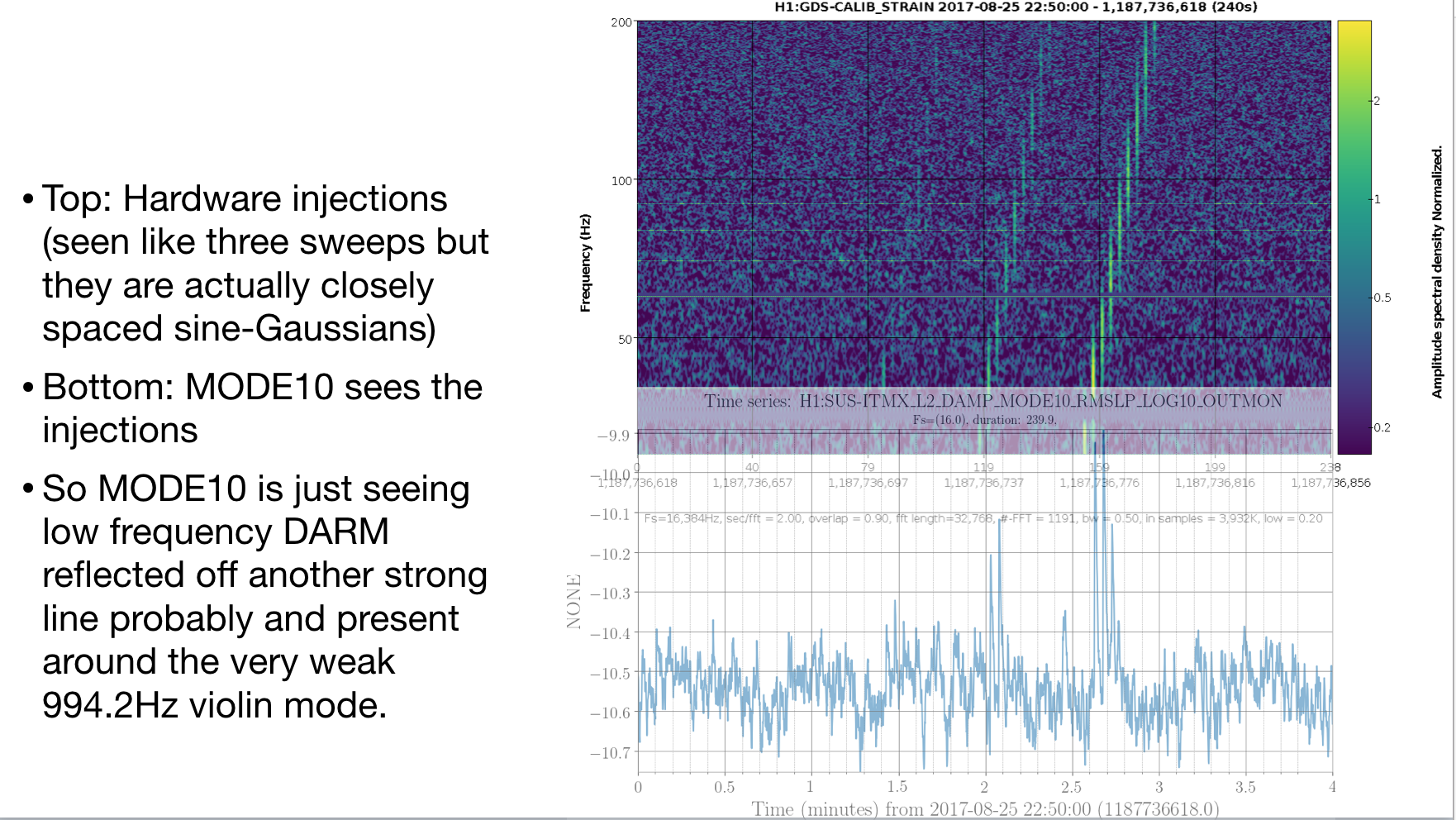
Figure 2 shows a 1-hour long line up of a strain spectrogram with the MODE10 timeseries. When the MODE10 channel goes above -10.4 there are some noise bumps in strain. 

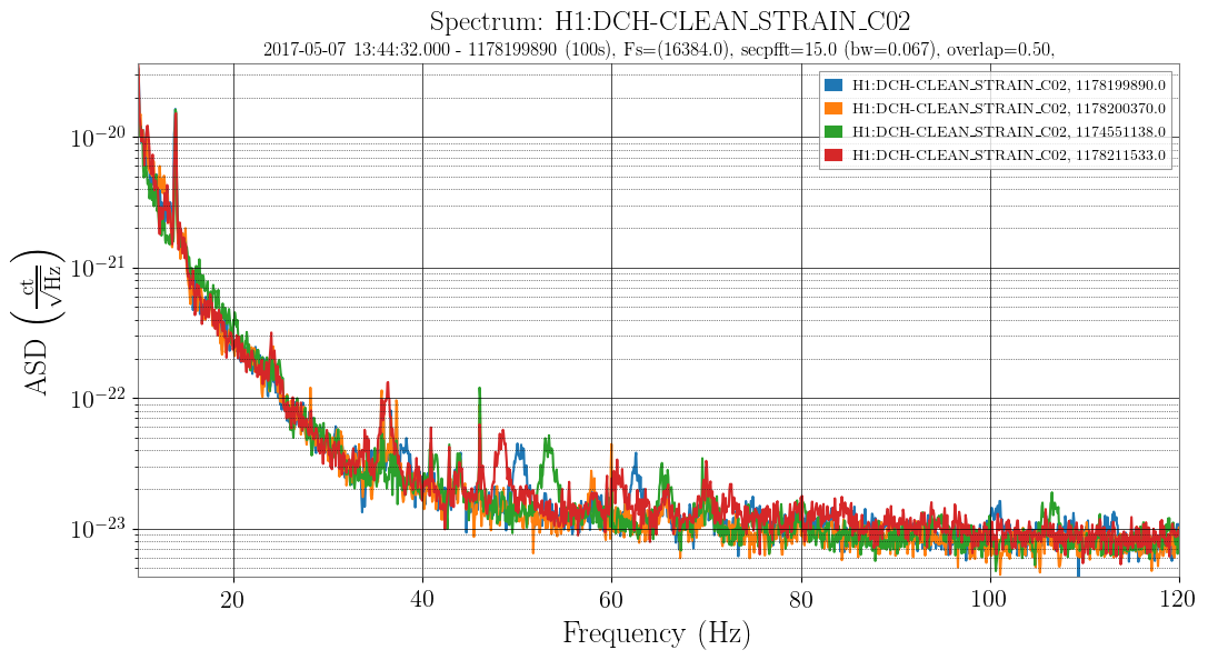
Figure 3 shows a cleaned strain ASD for a good time (orange) and three times when MODE10 was high and noise bumps were present (red, blue, green). The bumps are separated by about 12Hz and move around a few Hz from time to time. 

Attachment 4 is a multi-page PDF that walks though all of this in a little more detail and with labels on the plots (also in the DCC). 

Looking forward to checking this again in pre-O3 data. 
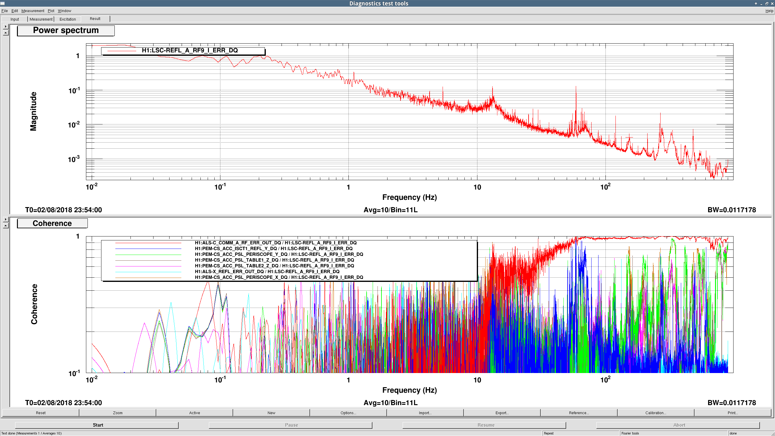
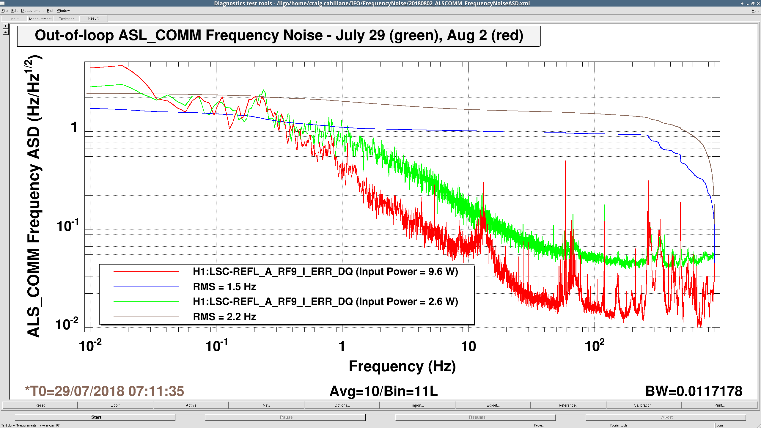
 

Images attached to this report
Non-image files attached to this report
Comments related to this report
joshua.smith@LIGO.ORG - 17:13, Thursday 02 August 2018 (43212)DetChar, SUS

Update/Retraction: In our detchar discussions we thought to look at whether the MODE10 channel could be just seeing low-frequency DARM reflected off another violin mode and overlapping the 994.27Hz "line" which is mostly buried in noise. It turns out this is true. This channel sees the Detchar hardware injections and picks up on the ones from 30-90Hz, as shown in the attachment. So this channel is "unsafe" because high frequency DARM has some low frequency DARM mixed into it. On the other hand, that reflection is not good. 

Images attached to this comment
H1 CDS
david.barker@LIGO.ORG - posted 13:19, Thursday 02 August 2018 - last comment - 16:27, Thursday 02 August 2018(43203)
Showing model's filter files differences, side by side in Vim

I've written a script called filter_diffs which displays the differences between the loaded filter file and the one in the chans/ directory (which is pending loading). The differences are shown side-by-side in a Vim session, which allows you to move up and down within the files. The details of the line differences are color coded.

To run the script:

filter_diffs MODEL_NAME

Attached is the output from running

filter_diffs h1susitmy

(It looks like foton has reordered the MODULES list and removed the spurious data_rate line)

Remember, to close all windows and exit Vim, type :qa

Images attached to this report
Comments related to this report
david.barker@LIGO.ORG - 16:27, Thursday 02 August 2018 (43210)

If, when vim is starting, you get the message:

Press ENTER or type command to continue

this can be fixed by editing your ~/.vimrc file and changing 'set syntax' to 'syntax on' (or entering the latter if you have no syntax directive)

H1 SUS (ISC)
jeffrey.kissel@LIGO.ORG - posted 15:57, Tuesday 31 July 2018 - last comment - 16:34, Thursday 02 August 2018(43150)
H1SUSETMX UIM/L1 L2A Transfer Functions Gathered
J. Kissel
https://tinyurl.com/LIGOSUSActuatorTuning Table

I've gathered the data necessary for the necessary re-design of the Longitudinal to Angle (L2A) decoupling filters for the UIM/L1 stage of H1SUSETMX. Attached are screenshots. Hang will take care of the filter design. For now, I've turned OFF all previous L2A decoupling filters (which were designed back in 2014, and only relevant for the former incarnation of ETMX).

The data can be found here:
   /ligo/svncommon/SusSVN/sus/trunk/QUAD/H1/ETMX/SAGL1/Data/
       2018-07-31_H1SUSETMX_L1_WhiteNoise_L_0p02to10Hz.xml
       2018-07-31_H1SUSETMX_L1_WhiteNoise_P_0p02to10Hz.xml
       2018-07-31_H1SUSETMX_L1_WhiteNoise_Y_0p02to10Hz.xml

This data was taken
(a) After the coils have been balanced (LHO aLOG 42740)
(b) With optical lever L2 damping OFF

I also attach play-by-play notes, if anyone's interested in playing along in the future. I'm still debating whether it's faster to just do the balancing, or to spend the time scripting.
Images attached to this report
Non-image files attached to this report
Comments related to this report
hang.yu@LIGO.ORG - 19:20, Wednesday 01 August 2018 (43189)

Jeff K., Hang

We fitted the freq-dependent L2P filters for the L1 stage. We could reduce some coherence below 0.6 Hz where most of the rms accumulates. See the attached image.

The traces were mostly taken when the L2 stage oplev damping was ON. The pink trace in the TF (top-left panel) was taken with the L2 oplev damp OFF. No significant changes in the residual TF was seen. This makes sense because we ff to cancel the torque perturbation before it enters the loop. As a side note, for the ISIFF, the Sidles-Sigg effect should also not affect the cancellation because it is also equivalent of a damping loop mediated by radiation pressure. We cancel the torque perturbation before it enters the loop (or another way to say it is that the loop affects the L drive -> P angle and P drive -> P angle in the same way and they should thus cancel out).

===============================================

Details

The filter we fitted is -(L1L -> L3P) / (L1P -> L3P). In the attached PDF it showed the fitted curve and the data. Note that we only have significant amount of rms after the sus resonance and thus we did not pay too much attention to the performance at > 1 Hz.

The zpk form of the filter we currently installed is (s-domain)

zpk(
[
-8.529494e+00+i*0.000000e+00; 
-2.849899e-01+i*2.457525e+00; -2.849899e-01-i*2.457525e+00; 
],
[
-1.639339e-01+i*2.326488e+00; -1.639339e-01-i*2.326488e+00; 
-1.519175e-01+i*2.962514e+00; -1.519175e-01-i*2.962514e+00; 
-1.562506e-02+i*1.332427e+01; -1.562506e-02-i*1.332427e+01; 
-5.756616e-01+i*4.883264e+00; -5.756616e-01-i*4.883264e+00; 
-1.793551e-01+i*1.232680e+01; -1.793551e-01-i*1.232680e+01; 
-3.751634e-01+i*6.337676e+00; -3.751634e-01-i*6.337676e+00; 
],
-1.154267e+05
)

In case someone wants to play with the data with IIRrational, he/she might want to run in bash

source /opt/rtcds/userapps/release/cds/h1/scripts/setup_anaconda; export PYTHONPATH=/ligo/home/hang.yu/Desktop/pyComm/:/ligo/home/hang.yu/.py_dev/lib/python2.7/site-packages/:$PYTHONPATH; source /ligo/home/hang.yu/.py_dev/bin/activate

This should activate my python installation with IIRrational. The jupyter notebook for the filter calculation can be found at

/ligo/home/hang.yu/Desktop/ASC/l2a/ETMX


Images attached to this comment
Non-image files attached to this comment
hang.yu@LIGO.ORG - 16:34, Thursday 02 August 2018 (43211)

We also did a L2A FF on vs off test with the ALS DIFF locked (actuating on ETMX L1 & L3 stages). See the attached plot.

The pink and cyan curves were with the L2A ON. The red and blue ones were with L2A OFF. For the L2A off ones, we could only stay locked for a single measurement. Nonetheless, the subtraction below 0.6 Hz seemed to be decent (around a factor of ~100 subtraction).


Images attached to this comment
Displaying reports 46261-46280 of 88222.Go to page Start 2310 2311 2312 2313 2314 2315 2316 2317 2318 End