Sheila, Jenne, Gabriele, Craig, Hang
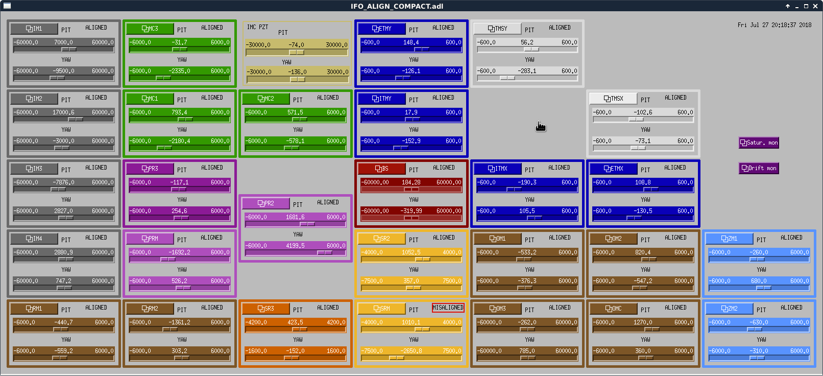
We moved the input beam to the POP_A QPD (the ASC one, PRM->PR2->POP_A) by moving the IM4, while compensating the alignment to XARM by moving PR2. The motivation is that we have not changed the alignment to POP_A since O2 and it may thus serve as a reference point for our alignment.
After the input beam centered onto the POP_A QPD, we then moved the ITMY with a combination of green WFS & human servo actuating on the ETMY and TMSY to move the YARM axis overlapping with the input. We also moved the on table alignment to keep the ALS COMM beatnote ~ -2 dBm, and ALS DIFF ~ -14 dBm.
In the Guardian, we modified the ALS green alignment setup so that both ETM and TMS are actively controlled during lock acquisition ('NO_SLOW_W_GR_WFS').
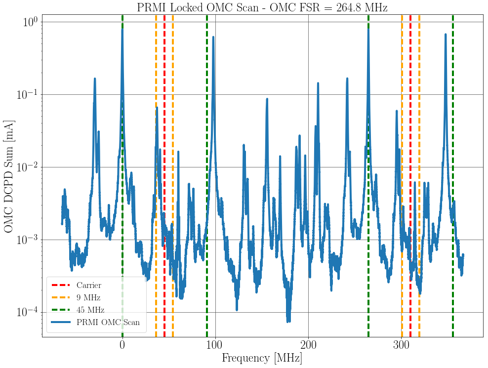
We now have ALS + PRMI locked with the input beam also on the POP_A.