I see what looked like an out-of-range moment at BRSX coincidental with a temp increase. Aside from that, BRS's seem to be within limits with BRSY showing a downward trend
The Variac that controls the Heat with Panel HC-1A had a failure of the top Variac.
Christina notice a smell. Chris S. Mark D. Richard M. tried to locate the source which was a definite electrical odor. Extended search desensitized us so brought in Ed M. and Corey G. . Corey was able to narrow it down to the Variac associated with Heater HC-1A
I have shut down the circuit and opened up the unit. Definite burn marks.
TITLE: 07/26 Day Shift: 15:00-23:00 UTC (08:00-16:00 PST), all times posted in UTC
STATE of H1: Commissioning
OUTGOING OPERATOR: None
CURRENT ENVIRONMENT:
Wind: 3mph Gusts, 1mph 5min avg
Primary useism: 0.03 μm/s
Secondary useism: 0.07 μm/s
QUICK SUMMARY:
Corey and I investigating burnt electrical smell in the mechanical room after Richard suggested we have a try to find the source.
also EY ISI is tripped.
Sheila, Hang, Jenne, Craig We are still baffled by our low PRMI gains according to POPAIR_B. We decided to do two OMC scans, one single bounce and one with PRMI locked, to get a second opinion of our PRMI alignment.Results
Measured 45 MHz Power Recycling Gain ~ 30 Modeled 45 MHz Power Recycling Gain = 48 This seems to indicate something is weird with POPAIR_B and not our alignment. Big if true.Details
OMC facts can be found from Koji. The most important fact for us is OMC FSR = 264.8 MHz. Plot 1 shows our single bounce OMC scan, while plot 2 shows the PRMI locked scan. We scanned the OMC by moving the PZT rail-to-rail at a constant rate over 200 seconds and read out OMC DCPD SUM milliamps. Both plots are calibrated from time to frequency using the OMC FSR between the two largest peaks. The tall clean peaks in the first plot are carrier, with visible 9 and 45 MHz sidebands. The sideband frequencies don't quite match up with peaks but our PZT isn't exactly linear so close enough. The 45 MHz sideband appeared in the OMC DCPD with 0.03 mA. The peaks in the PRMI locked scan are the 45 MHz sidebands. They are not balanced: 54% of the 45 MHz power is in the lower sideband:PRMI Max OMC DCPD -45 MHz = 0.79 mA +45 MHz = 0.67 mAHere we calculated the PRMI recycling gain from first principles.where
Then we estimated our current recycling gain from the measurement ratio of PRMI 45 MHz/singleBounce 45 MHz:
For single bounce:
Some cavity math:
Yields:
Transmission Ratios:
PRMI -45 MHz/Single Bounce 45 MHz: 25.8351036066 PRMI +45 MHz/Single Bounce 45 MHz: 22.1094695082PRMI Power Recycling Gains:-45MHz = 33.36 +45MHz = 28.55
Conclusion:
There are three ways we can try to estimate PRMI gains: OMC scans (PRMI compared to single bounce), ASC POP sum/IM4 trans sum, and POPAIR B 2F signals. The OMC scan Craig describes above is the most reliable, and indicates that we have been fooled by POP90 into thinking that our recycling gain is much worse than it really is.
Details:
| May 26 2018 2:50 UTC | June 21 2018 10:00:00 UTC | July 25 18:07 UTC | |
| POPAIR B 18 I NORM (counts) | 50 | 27.5 | 7 |
| POPAIR B 90 I NORM (counts) | 75 | 40 | 19.4 |
| IM4 TRANS SUM (uW) | 54.9 | 272.3 | 279.6 |
| ASC POP A SUM/ IM4 TRANS SUM (uW/uW) | 4.7% | 6% | 2% |
| POP 18 demod RF MON (dBm at input to demod) | -49.5 | -41 | -49 |
| POP 90 demod RF MON (dBm at input to demod) | -46.2 | -38.4 | -46 |
ASC POP is unreliable because we are falling off the diodes. We don't want to pico to center ASC POP because this is one of our few alignment references from O2 that has not changed.
Yesterday's OMC scans indicate that we have 62% of the maximum possible build up for 45 MHz. This implies that something has gone wrong with POPAIR B (clipping, or something electrical) between May and now. If we scale the recycling gain measured last night to POP 90 we would infer that the recycling gain ifor 45 MHz in May was 115, or 2.5 times higher than what we think is the maximum possible.
Thanks to Anamaria for suggesting that we try the OMC scans.
Some clarification of the PRMI 45 MHz gain calculation: I referenced Kiwamu and Daniel's aLIGO paper for some numbers, in particular the Schnupp asymmetry of 4 cm. PR2 and PR3 transmission losses were not included.where
![]()
![]()
![]()
![]()
![]()
Danny, TJ, Georgia
This afternoon while the arms were locked in green and team ALS were checking the DIFF PLL, we checked and tweaked up the alignment of the ITMX and ITMY Hartmann wavefront sensors.
With the new alignment as of this afternoon (see attached screenshot of sliders during this work) green beams from ITMX and ITMY made it out to the Hartmann table. We tweaked both the ITM HWS table periscope mirrors to get the beams onto their respective sensors.
We also tweaked up the alignment of the SLED for ITMY, which was misaligned on the first periscope for some reason. We should possibly check that everything on the SLED path is appropriately bolted down?
To get the HWS cameras to stream TJ had to run a thinning script as the computer was full. We streamed images from the Hartmann cameras, and steered around the periscope mirrors to see the SR3 baffle and Hartmann baffle on the ITMX sensor, and SR3 baffle on the ITMY sensor. Danny will comment with screenshots of the stream.
Meanwhile, Danny has blocked CO2X on table for the time being.
Updates on SQZT6:
- Diagnostic test laser moved.
- LO fiber coupler patch panel moved to the left side of the table, because of the limit length of fiber on table.
I tried to use an electronic fiber microscope that we have to inspect the long green fiber, but the coupler doesn't fit well..
A pic of the SQZT6 table fiber end is attached, the cladding part looks good. The coating part of the tip has some dusts (too hard to take a picture), and I cleaned it gently. Will check more on this with the other microscope.
TITLE: 07/25 Day Shift: 15:00-23:00 UTC (08:00-16:00 PST), all times posted in UTC
STATE of H1: Commissioning
INCOMING OPERATOR: None
SHIFT SUMMARY:
LOG:
15:30 Vanessa out to EX - cleaning
16:00 BRS sensor correction turned off - suspect cleaning activities caused some perturbance at EX. Perhaps some seismic concessions to be made for these morning activities.
16:32 pursuant to the last entry: ISI and TMS at EX tripped. Jim reset ISI wd, straight away. TMSX wd was reset 27 minutes later - verbal alarms volume was turned down.
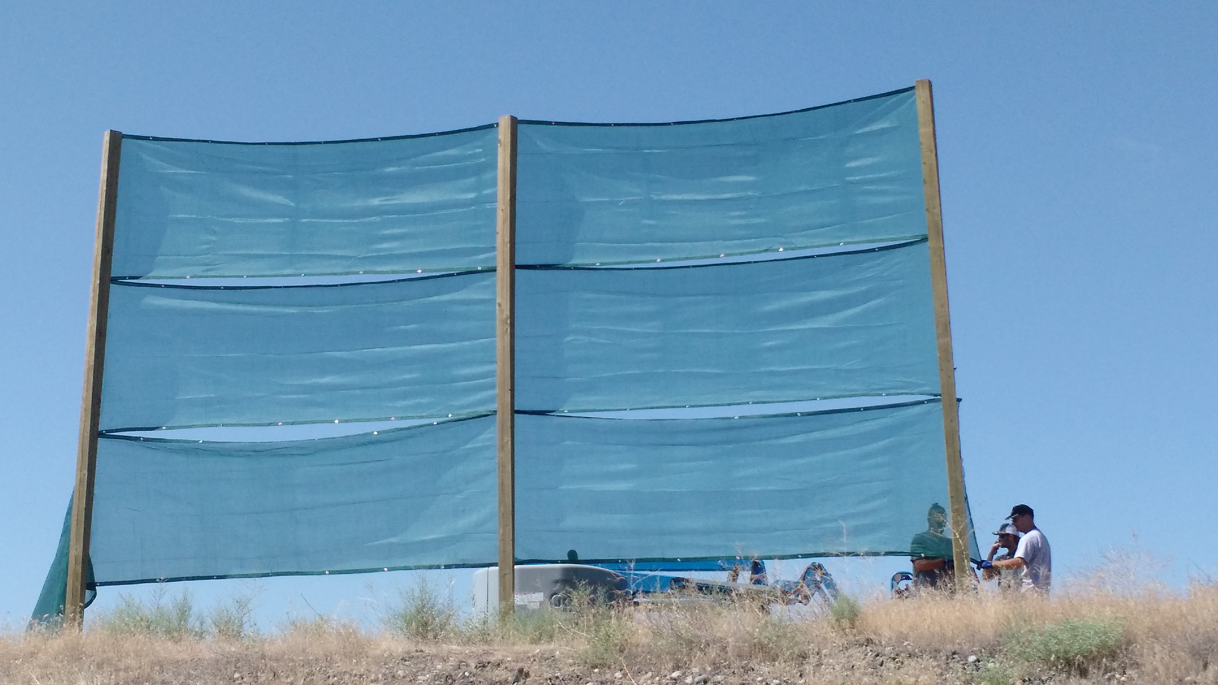
16:54 Richard out to EX to talk to the wind-fence crew - Mark, Tyler, and Chris.
17:07 Dave B restarting digital video camera server
17:16 Haocun out to HAM6 area
17:17 Fil out to CER to power cycle illuminator ckt for BSC2
17:20 Fil back
18:45 Jeff B out to clean area
18:50 Jeff back
19:15 Georgia and Dave out to ISCT1
19:52 Georgia back
19:55 Carlos out to LVEA ISCT1 to verify operation.
20:01 Kyle out to EX vea
20:06 NDS server restart
20:15 Haocun back
20:24 Carlos back
20:36 Kyle back from EX
20:55 HWS team out to LVEA - TJ, Georgia, and Daniel
21:13 Gerardo out to both arms xx-8(where solar panels are) to visit ion pumps
21:59 HWS team out
22:00 Weekly Site Meeting
Yesterday Richard and I tried to identify as many of the analog cameras as we could because the labels on the medm screen aren't accurate.
Using the camera number (which shows up in a small box at the top of the medm screen when you select a camera)
We identified the following cameras:
There are several other cameras that are connected but we couldn't identify what they are looking at. One of these should be the POP AIR camera. These include: 22,23,24,27, and 52
There are no connections for the remainder: 3-14, 17-19, 25, 28-30,32, 34-52, 54-58, 61, and 64-72
Carlos, Dave:
Carlos repaired opsws2 (the iMac which was originally at ISCT1). In the mean time, opsws5 was relocated to ISCT1 but found to have a login issue. Today opsws2 was returned and opsws5 removed for repair. Carlos verified that the iMac by the PSL enclosure (lveaws3) and the iMac by HAM6 (operator1) were in good working order. So three operational iMacs (two portable) in the LVEA and one out for repair, and of course CDS laptops can be used to augment these.
WP7725 Offload raw minute trend files from h1tw1's almost full SSD-RAID
Dave:
The first step in the offload process is to start writing the most recent data to a new directory, freeing up the old directory for file transfer and verification.
Since this process takes about 3 days, the NDS processes need to be reconfigured to use the temporary location of the past 6 months of data so minute trends can continue to be used.
At 13:06 PDT I restarted h1nds1 (the default NDS for the control room), minute trends back to 09 March 2018 are available from their temporary location.
Open dataviewer sessions will need to be reconnected to the NDS.
starting the file transfer, a process on h1fw1 is copying from h1tw1 to h1ldasgw1 using 'ionice -c 3' which should only be granted disk access when the system is idle.
The crew gets the new 50% porosity fabric installed on the prototype fence. It spans from 20' at the top to 4' from the bottom and is 30 feet wide over three posts.
Thanks to the crew: MarkD TylerG and ChrisS for battling with soft sand and flies not to mention the 100° temps.
This morning I tried a different approach to explore the alignment of IM3/IM4 to improve PRMI buildup.
A script then reads the OPTICALIGN values and the RF18_I_NORM signal with PRMI locked. Then a quadratic form is fitted to the power fluctuations, using the IM3 and IM4 excitations as input. In other words, if X is a vector of IM3 and IM4 offsets:
X = ['H1:SUS-IM3_M1_OPTICALIGN_P_OUT16', 'H1:SUS-IM3_M1_OPTICALIGN_Y_OUT16', 'H1:SUS-IM4_M1_OPTICALIGN_P_OUT16', 'H1:SUS-IM4_M1_OPTICALIGN_Y_OUT16']
Then RF18_I_NORM is recosntructed with parameters A (4x4 matrix), B (vector of size 4) and C (scalar constant):
RF18 = X.T * A * X + B * X + C
The fit is quite good:
Then from the A and B coefficients I could compute the new IM3 and IM4 offset values that would give the largest RF18 power. The values found in this way were about 1000 cts off in picth and almost unchanged in yaw. I tried them, and found that RF18 improved a bit, but not a lot (from ~7.0 to ~7.17).
So no big improvement, but at least the method seems to work.
Nolan Marc Dick Daniel
We swapped the ALS PFD with a unit that had its LO TNC/PCB/SMA/SMA/coax/SMA input arrangement replaced by a simple TNC/coax/SMA. Furthermore, the TNC connectors are no longer isolated. This should reduce any crosstalk inside the PFD between the 2 ALS VCOs.
While we were at the rack we noticed that some of the N bulkheads in the VCOs and FDDs were very loose. One of them rattled when we wiggled the cable. We tightened them all. We noticed that one of the cables between the VCO and the FDD had 2 ~5dB attenuator installed, whereas the other one had none. This was fixed as well. Both FDDs now have a proper 13dBm at the input.
The modification is documented in this ALOG from LLO, with pictures!
https://alog.ligo-la.caltech.edu/aLOG/index.php?callRep=26227
The SN of the unmodified PFD we removed is S1000761. The SN of the modified spare PFD we installed is S1000756.