Nolan Marc Dick Daniel
We swapped the ALS PFD with a unit that had its LO TNC/PCB/SMA/SMA/coax/SMA input arrangement replaced by a simple TNC/coax/SMA. Furthermore, the TNC connectors are no longer isolated. This should reduce any crosstalk inside the PFD between the 2 ALS VCOs.
While we were at the rack we noticed that some of the N bulkheads in the VCOs and FDDs were very loose. One of them rattled when we wiggled the cable. We tightened them all. We noticed that one of the cables between the VCO and the FDD had 2 ~5dB attenuator installed, whereas the other one had none. This was fixed as well. Both FDDs now have a proper 13dBm at the input.
This morning some models went from RCG3.2 to RCG3.2.3. Changes made in RCG3.2.1 mean that when an updated model is ran with mx_stream-3.2 (the code which sends the model's data to the DAQ), the keep-alive message coming back from the DAQ Data Concentrator is not interpreted correctly and the front-end DAQ bit is erroneously set bad.
The data from the model to the DAQ is perfectly correct, and the status of the data flow as determined by the Data Concentrator is correct.
There are three options:
1. make no changes, accept that the CDS overview will have red daq bits for some models
2. for models running 2.3.2, do not show the DAQ bit on the overview
3. for any front end with at least one model running 3.2.3, upgrade all the models on the computer to 3.2.3 (including IOP) and run mx_stream-3.2.3
I don't want to do 1), this can lead to red-fatigue when viewing the overview.
Option 3 is intrusive and will require customization of the monit script which starts mx_stream in order to start the correct version depending upon the computer name. It will require upgrading all models on h1susb123, h1seib2, h1susex and h1susey (and possibly on h1asc0 or downgrading h1asc model to RCG3.2).
For now I'm implemented option 2). A new composite fec-status MEDM called H1CDS_FE_3_2_3_MICRO_CUST.adl has been created and used for the models h1sus[i,e]tm[x,y], h1isibs, h1asc.
I tested these options on h1pemmx. It is currently running 2.3.2 on IOP and h1pemmx, and mx_stream-3.2.3.
I have reset the build release pointers back to RCG3.2 for now.
Did inspection of air ducting into the PSL enclosure. All appears to be in order. I found no breaks or damage to the ducting. The seals between the ducting and the hole in the roof were all intact. The damper on the discharge ducting is moving freely and appears to be working. I did find pieces of insulation like material inside the discharge duct. This may be an artifact of the duct assembly. Inspected the fan/filter units on top of the PSL Anti-room. All the prefilters are intact. They have expected surface contamination, but nothing out of the ordinary. In the "plenum" area between the prefilter and the fan unit (on the three fan/filter units inspected)I found moderate amounts of dust. The dust is concentrated around the edges of the plenum box, indicating it is outside the area of the air being drawn into the fan. At some point it may be good practice to clean these units, but this is not a pressing issue. Conclusion: Good News - The air ducting system seems to be operating as designed. It does not appear to be contributing to spikes in the particulate counts within the PSL Anti-room or laser enclosure. The HEPI filters were not inspected due to the disruption an inspection would cause.
Interface board replaced with v6 board. New board has whitening/gain for EFM signals. EFM gain increased:
R10/R16 changed to 10K
R14 changed to 4.99K
With ion pump replacement going on at EX, we decided to leave the ±18V going into chamber off.
S1102829 - Chassis
S1800797 - Interface board
J. Kissel, D. Barker ECR E1700286 WP 7720 FRS / IIET Tickets 8759, 11032, 11066 We've made an (and hopefully last) attempt at installing the violin mode filter expansion pack. All signs point to success! As an addition to the three-weeks-ago first attempt, I've added a bit more output monitoring and control so as to - prevent the violin mode filters from blasting the PUM upon accidental startup - facilitate a quick shut-off of ALL violin mode damping output, instead of having to turn off 40 filter bank outputs. I've also identified a few MEDM screen bugs and fixed those up I've fixed up along the way. The short summary of the story: - originally tried installing three weeks ago (LHO aLOG 42752) - found that the installation surpassed some real-time code generator (RCG) threshold and caused a bug in the binary IO system (LHO aLOG 42922) - Rolf found and fixed the bug (see LHO Ticket 11066, Comment #7), and was tried and tested at LLO (LHO aLOG 39785) - And now re-installed today, with a bit of improvement in output monitoring and control. I've committed changes to: Front-end model library part: /opt/rtcds/userapps/release/sus/common/models/ FOUROSEM_DAMPED_STAGE_MASTER_WITH_DAMP_MODE.mdl MEDM Screens: /opt/rtcds/userapps/release/sus/common/medm/quad/ SUS_CUST_QUAD_L2_DAMP_MODE_MTRX.adl SUS_CUST_QUAD_L2_DAMP.adl SUS_CUST_QUAD_ITM_OVERVIEW.adl SUS_CUST_QUAD_OVERVIEW.adl which are all common library parts, so the update at LLO should be very straightforward.
This closes FRS Ticket 11032 and IIET Ticket 11066.
[Georgia, Gabriele]
We went to the LVEA to focus the PR2 camera on visible light, with various setting of the illuminator on. We took a few images with various zoom levels, and then set a zoom that provides a good view of the scraper baffle aperture. The image below shows the view with the illuminator on and the final zoom level.
We then focused again the camera on the infrared beam. We also wrote a simple python script to superimpose the IR image (in red) with the reference visible light image (background). The results is shown below in single bounce configuration:
For reference, photos of the table can be found in 38749:
Attached a new version of the script, that takes continuous snapshots and display them in real time.
WP7730 Beam Splitter ISI to SUS feed forward signaling
Jeff K, Dave:
New h1isibs and h1susbs models were installed. New IPC Dolphin channels added.
WP7719 QPD arm transmission on ASC ADS
Hang, Jennie, Dave:
New h1asc model was installed. Installation had an issue with the H1ASC.txt filter file having incorrect file permissions, I fixed this and installed a second time.
WP7721 Add AC power strip status channels to DAQ
Dave:
New H1EDCU_CDSACPWR.ini added to DAQ. This allows the trending of the ALS polarization correction box's powered status.
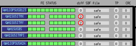
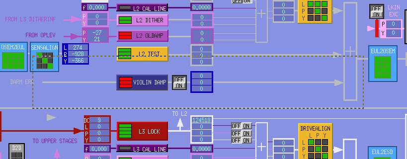
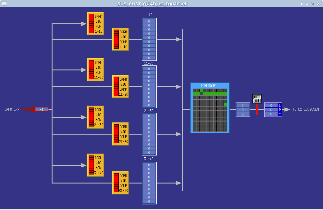
WP7720 RCG upgrade to 3.2.3, add violin mode damping filtermodule back to SUS-QUAD
Jeff K, Dave:
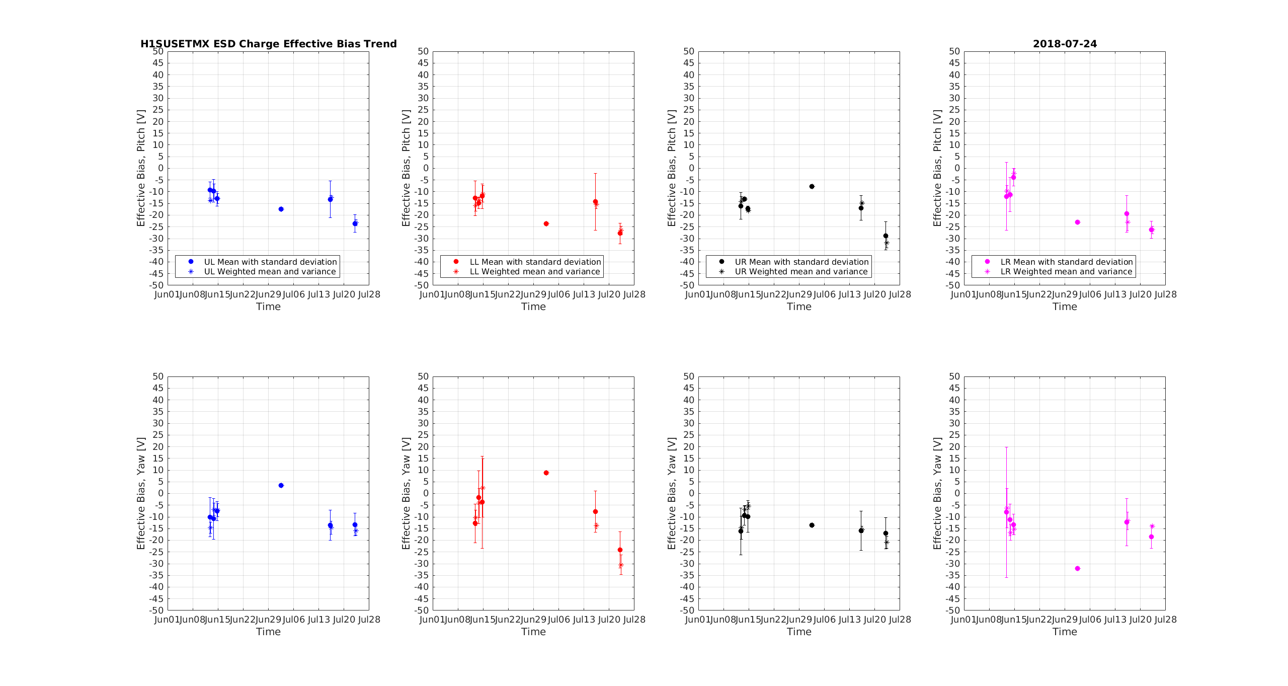
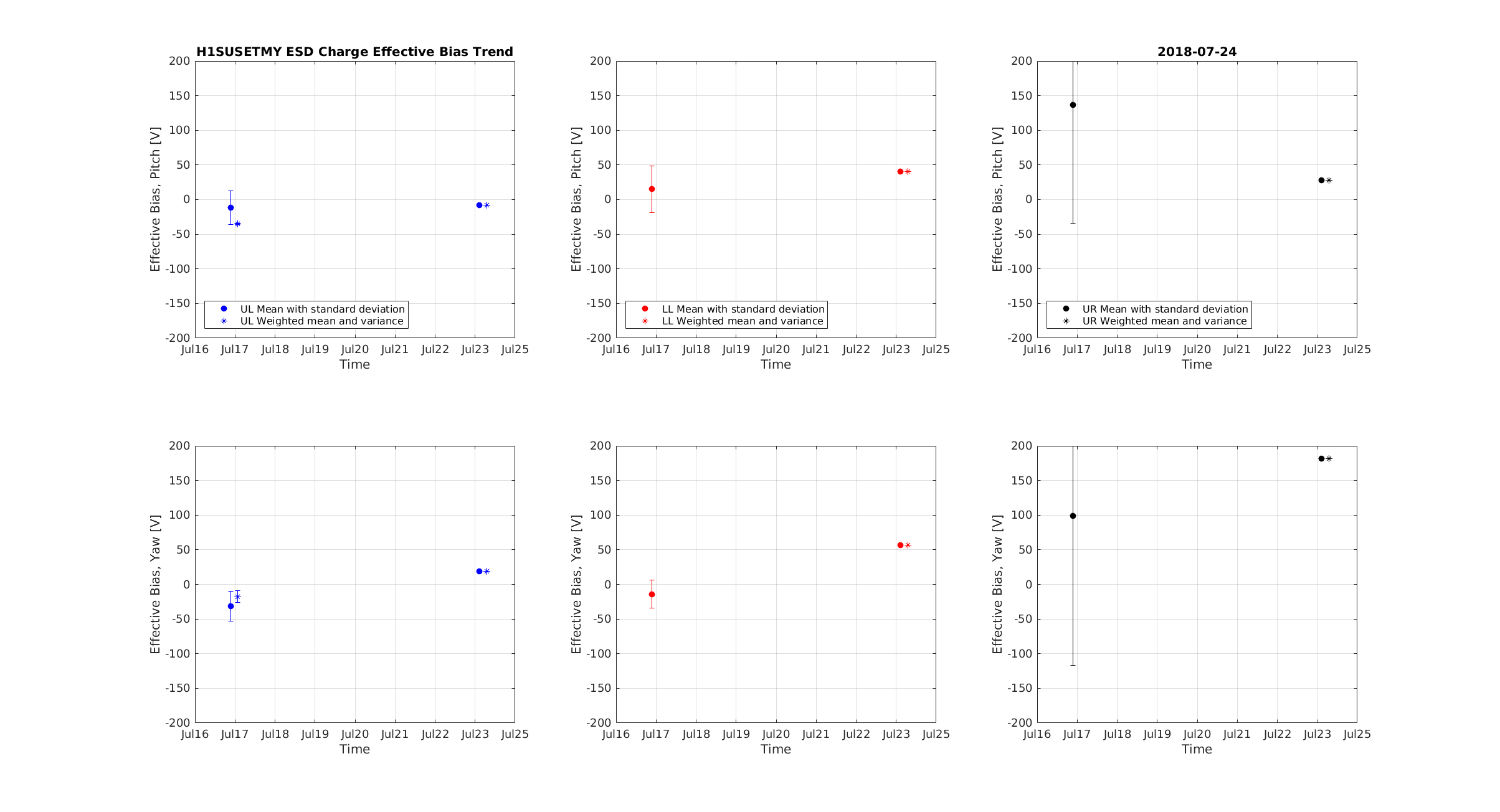
New h1susitmx, h1susitmy, h1susetmx, h1susetmy models were built against RCG3.2.3 and installed. All models from now onwards will be built using 3.2.3, including those built today.
Guardian DIAG_MAIN reports if polarization correction box is powered on for an extended time
TJ, Dave:
TJ modified DIAG_MAIN to report if polcorr box is powered on. This is intended as a reminder to power it off before going to science mode.
WP7724 Restrict who gets messages when Cell Phone Alarms system is stopped/started
Following the unexpected restart of the system last Saturday night, I have restricted who gets notified when the system starts (and when it is manually stopped). Only myself gets a cell phone text, everyone else only gets emails. System was restarted several times to test this. The daily CP, GP reports do not automatically get sent on restart anymore, they can be manually sent by issuing a SIGUSR2 signal.
DAQ Restart
Dave:
One DAQ restart at 10:38 to cover all of the above.
Pending filter module modifications manually loaded
Dave:
I loaded all filters for the following systems: h1susetmx*, h1sustmsx, h1alsex, h1asc* (systems marked * were loaded as part of their restart process).
h0epics restart
Carlos, Dave
h0epics unexpectedly went down. After Carlos got it running again, I started the EPICS IOC which reside on this system: h1weather[ex, ey, mx, my], h1dus[lvea, lab, ex,ey,dr], dewpoint.
You can verify which version of RCG was used to build a model by looking at the upper left hand corner of the GDS_TP MEDM screen. Most models were built with 3.2 (denoted 3.20) and today's models have been built with 3.2.3 (denoted 3.23).
J. Kissel
Since we'll be restarting the QUADs (ITMX, ITMY, ETMX, ETMY) again this morning, and now also the Beam Splitter (BS), I've reconciled the SDF system to the best of my ability.
ETMX
- restored to optical lever damping OFF (was ON with a gain of 30)
- restored ESDOUTF offsets and tramps to zero (left over from charge measurements)
- ACCEPTED all outputs of existing violin mode damping filters to be OFF
- ACCEPTED the new L2A filters and gains from Hang's Work a few weeks ago (I'm kind of surprised it wasn't already accepted).
ITMX
- restored to optical lever damping OFF (was ON with a gain of 30)
- ACCEPTED all outputs of existing violin mode damping filters to be OFF
- ACCEPTED new values for misalignment offsets.
ITMY
- reverted to optical lever damping OFF (was ON with a gain of 30)
- ACCEPTED all outputs of existing violin mode damping filters to be OFF
- ACCEPTED a ~100 urad change in R0 alignment offset.
- ACCEPTED new values for misalignment offsets.
ETMY
- reverted to optical lever damping OFF (was ON with a gain of 30)
- ACCEPTED all outputs of existing violin mode damping filters to be OFF
- ACCEPTED changes to ETMY_M0_LOCK_P/Y to have it's inputs OFF and FM1 OFF, but this appears to be manipulated by guardian, so we should investigate not monitoring these channels.
BS
- reverted optical lever damping tramps to 20 sec (from 10)
- reverted having limiters on the M1 LOCK filter banks.
For the ease of recovery, I've also saved all of the alignment offsets for the above mentioned suspensions.
Summary: Ran Charge measurements for ETMx & ETMy from 7:23-8:30amPDT a little early this morning for morning commissioning work. There was a big EQ which occurred during this measurement.
Morning Activity:
* ISC_LOCK would not go to DOWN (said there was no path from READY to DOWN, & would go for PREP_FOR_LOCKING). Took to MANUAL & then selected DOWN; stayed in MANUAL for measurements.
Checking Data/Files:
I had trouble running the matlab files to analyze the data last week. So, for today I'm only checking to see that the data was posted. Similar to last week, we have 5-sets of measurement folders which contain the usual 5-data files per quadrant. Sending an email to Georgia & JeffK to let them know I ran the measurement & data ready for analysis.
Restoration Notes:
**ETM ALIGNED Slider values (before centering Oplevs)
ETMx:
ETMy:
I think I have worked around some of the problems in the old ESD_analysis script by commenting out some lines which didn't make sense; comments labelled GM to ease finding them again. I am planning to completely revamp it and include my 4-parameter script in the usual charge measurements.
Posting the results of the op-lev effective bias measurement for ETMX (believable) and ETMY (broken LR quadrant not included, UR quadrant dubious as for some reason this stream of data is much shorter than the others).
These measurements show ETMX has a fairly consistent negative V_eff across all 4 quadrants of <30V magnitude. ETMY is harder to interpret, with fewer data points, but it does look like the LL quadrant has a higher V_eff than UL.
Sheila, Anamaria
I made spectrograms of the scan from the previous night, which ran for close to 10 hours. We notice similar lines appearing and disappearing with the VCO frequency, like we do at LLO. This is encouraging, in that our best guess is that it's some artifact of the VCO electronics.
On the other hand, unclear what it means for whistles in full lock. There seem to be larger swaths of VCO frequencies (than at LLO) where nothing happens, so that's one option for explaining why LLO DARM whistles and LHO DARM does not. (We hope these lines are a symptom of the same phenomenon as in full lock, when MCF moves by 10s of kHz and these lines would become whistles,but we don't know)
Figures for the full scan, in 100 sec increments, can be found at: https://llocds.ligo-la.caltech.edu/data/dtt/Anamaria/public/imcvco/LHOsweepJul23/
The plots show whitened spectrograms:
- IMC-F at the top with a green overlay of the IMC-F DC value which would have to be multiplied by 3 to be true Hz;
- ISS out of loop sensor, with a yellow overlay of the VCO frequency, in Hz, but with the starting frequency subtracted (the value at bottom left) and shifted by 3kHz to be in the approx middle of the graph;
- the OMC-DCPD_SUM spectrogram.
I attach four examples:
- lines only seen in OMC, first plot
-lines seen in both OMC and ISS, second plot
- two different "orders" in MCF only, third and fourth plots.
Sheila, Hang, Jenne, Gabriele, Craig
After the contrast defect was fixed this afternoon, we tried to lock PRMI and saw that we still have poor build ups.
PR2 Camera
Single bounce clipping checks
After this we closed a loop from AS_C to ITMX (then implemented a human servo which was much faster) to scan the angles of IM4 and PR2 while watching the AS QPD sums to see where the edges of the apertures are.
It seems that the limiting aperture for IM4 pointing is the scrapper baffle, and that we are more likely to be clipping on that than anything else in the PRC.
TJ, Georgia, Danny
Just a quick look here that I'll follow up on in a day or 7.
On HAM3, it looks like the gain switch on H1 corner for the GS13 produces a step and possibly a DC shift. That does not seem good.
I just quickly scanned back through the data and looked for a GS13 BIO switch event that had a trip. I don't know whether it is guardian or Jim's python script doing the switching.
On the first plot there are all six HAM3 GS13INFs; it looks like H1 switches first (red). The Step and Offset are fairly clear. In the second plot you can see this step/offset with the BIO channels showing that the step/offset occurs during the switching process. H2 also switches before the WD trip registers (3rd plot) and although it might be influenced by the trip that is commencing, it does not appear to have the step/offset seen on H1. All other GS13s don't actually switch until after the WD has registered the trip state and their signals have already blown up. Not to say that these other corners wouldn't look the same if the switching were reordered. Mind the channel names--the colors are not consistent.
Bottom line, the HAM3 H1 exhibits a step/offset that is not good, IMHO.
Attached graph compares Beam Tube pressure at each end of the X-arm --- hmmmm.
This is in preparation for tomorrow's continuance of WP #7723 work at X-end
16:30 JeffB to MSR
16:45 Karen to optics lab
16:45 Danny, Georgia to CO2X
16:45 Ed to LVEA to look for PR3 oplev spot
17:00 Kyle to LVEA, then to EX
17:45 Hugh to EX
22:00 TJ to transition EX
22:15 TJ, Danny, Georgia to CO2X
J. Kissel, H. Yu
I’ve created a table for us to keep track of what we’ve done and/or what needs to be done regarding globally controlled “ISC" SUS
- Scalar Coil Balancing
- Long to Angle Frequency Dependent Feed Forward ("L2A")
- ISI to Top Mass Frequency Dependent Feed Forward
- Scalar Angle to Long Feed Forward (“A2L”)
You can find the table here:
https://tinyurl.com/LIGOSUSActuatorTuning
(original link is https://docs.google.com/spreadsheets/d/17JAoAQ18N7A3XhECXNkwmu6qk3hkuiQGJsz8AnNHAqA/edit?usp=sharing)
There’s a tab for LLO and LHO down at the bottom (the link will likely take you to LLO first). I’ve filled out a prioritization of LHO’s as I’m imagining it at this point, since we’ve got a lot of work ahead of us.
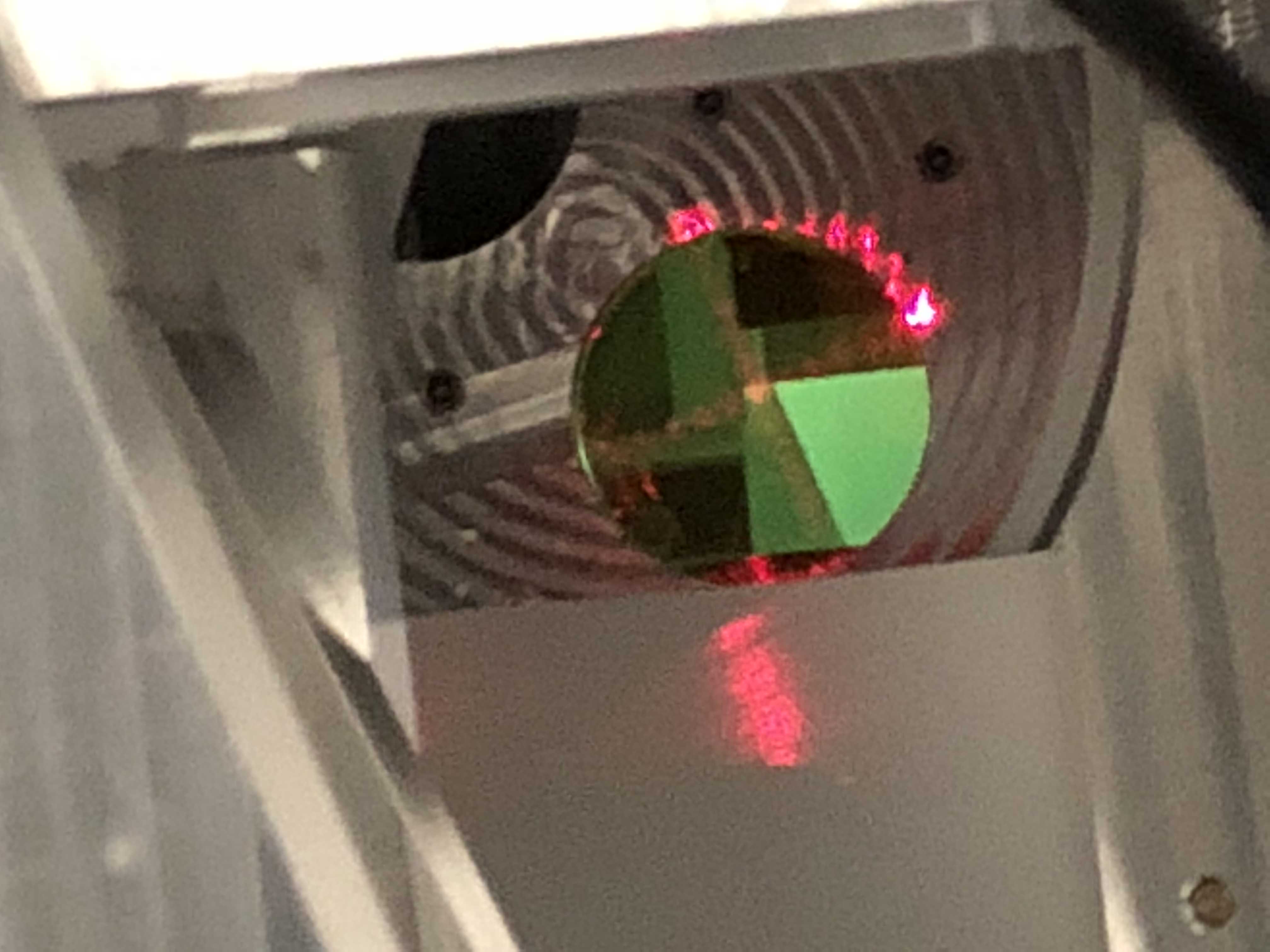
The modification is documented in this ALOG from LLO, with pictures!
https://alog.ligo-la.caltech.edu/aLOG/index.php?callRep=26227
The SN of the unmodified PFD we removed is S1000761. The SN of the modified spare PFD we installed is S1000756.