Displaying reports 46481-46500 of 88171.Go to page Start 2321 2322 2323 2324 2325 2326 2327 2328 2329 End
Reports until 12:46, Tuesday 17 July 2018
H1 PSL (PSL)
peter.king@LIGO.ORG - posted 12:46, Tuesday 17 July 2018 - last comment - 12:51, Tuesday 17 July 2018(42938)
ISS AOM driver power
With the ISS AOM driver disconnected, the output of the 24V power strip was -25.39V and
+23.83V.  The driver only uses the +24V power form.  A new, larger gauge power cable was
pulled in.  +24.8V was measured at the business end of the cable.


  Fil / Richard / Peter
Comments related to this report
peter.king@LIGO.ORG - 12:51, Tuesday 17 July 2018 (42939)
Turned on the AOM driver and aligned the AOM.  Saw the diffracted beam.  Took some
diffracted power versus applied offset slider data.  At the moment we are diffracting
~1.6W.

    The ISS still needs a reasonable amount of tweaking and adjustment.


  Jason / Peter
H1 CDS (DAQ)
david.barker@LIGO.ORG - posted 12:45, Tuesday 17 July 2018 (42937)
CDS Maintenance Summary

WP7716 Revert SUS QUAD models to reduce number of violin mode damping filters.

Jeff K, Dave:

All four SUS quad models were restarted, the recent addition of extra violin mode damping filters was reverted. DAQ restart was needed.

Fixed ADC channel bug in h1pemcs

Dave:

I fixed the ESD voltage monitor channels in h1pemcs and restarted the model. DAQ restart was not needed.

Guardian ISI_HAM3 node restarted after lock file removed

TJ, Dave:

We removed a lock file which was preventing GRD ISI_HAM3 from restarting.

h1seih23 IO Chassis power cycle to hard reset BIO card

Hugh, Dave:

We power cycled h1seih23 (cpu and IO Chassis) in order to hard reset of the Contec 64/64 binary IO card. This is part of the watchdog tripping investigation when digital/analog filters are switched. Looks like it did not improve the situation.

The power up sequence as defined in T1600332 was followed (https://dcc.ligo.org/LIGO-T1600332)

H1 General (SUS)
edmond.merilh@LIGO.ORG - posted 10:37, Tuesday 17 July 2018 (42934)
ETMY and ITMX Oplevs Centered

I centered the ETMY oplev last evening and the ITMX oplev just now.

H1 AOS
daniel.vander-hyde@LIGO.ORG - posted 10:17, Tuesday 17 July 2018 - last comment - 18:23, Tuesday 17 July 2018(42932)
CO2X on-table alignment

TVo, Danny

Currently CO2X is not very well aligned on the FLIR as well as the central and annular masks before it (see attached images). TVo and I plan on centering this soon. Hopefully this helps center CO2X on the CP as well. 

Images attached to this report
Comments related to this report
thomas.vo@LIGO.ORG - 18:23, Tuesday 17 July 2018 (42947)

We aligned the CO2X beam onto the FLIR but the central and annular masks still need to be aligned to the beam. 

Images attached to this comment
H1 CDS (CDS, SUS)
jeffrey.kissel@LIGO.ORG - posted 09:39, Tuesday 17 July 2018 - last comment - 10:46, Tuesday 17 July 2018(42929)
H1 SUS ITM Hardware Watchdog (HWWD) LEDs Glitching, No excess motion on ITMs
J. Kissel, E. Merilh

While I was reconciling the QUAD SDF screens, I would occasionally see a channel from the Hardware Watchdogs (HWWDs) pop in and out of difference. Digging deeping into the MEDM screen for it, we found both ITMX and ITMY would flash the "LED" value red for a ~few seconds (H1:SUS-ITM[X/Y]_HWWD_STAT_OUT), start the countdown for shut down (H1:SUS-ITM[X/Y]_HWWD_TTF_MIN and H1:SUS-ITM[X/Y]_HWWD_TTF_SEC), and then flip back to green and happy. 

The glitching seems to have been going on all morning (see attached DTT time series of some 12 minutes taken while I was writing this aLOG). The channels appear to be a bit word, but I'm not sure what the meaning of 8 (or 2^3, or the third least significant bit) means.

Of course, we had to check whether the QUADs were moving at all -- no dice. The trigger signals for the HWWD on equivalent Independent Software Watchdog (SWWD) screens -- RMS signals of the main chain (M0) top mass OSEMs -- are hovering around their usual ~0.1-0.3 mV RMS, which is WELL below the 110 mV threshold. Manually inspecting the ITM overview screens for excess motion, we see none. BSC-ISIs are happily in FULLY ISOLATED, SUS-ITMs in a DAMPED state, ALS green slowly / peacefully flashing. All sensors (and there are LOTS) report that it's all quiet on the LVEA front.

Seeing no evidence for excess motion (even with Hugh inspecting HEPI for inventory around the ITM BSC chambers), we suspect something's awry with the electronics. Watching the GDS TP screens, the brief red status doesn't appear to coincide with any timing errors or IPC miscommunications.

This may be a repeat of what we saw during O2, where the watchdog STATE (not STAT_OUT?) popped up to 8:
Event 1: Aug 2017, LHO aLOG 37971, FRS Ticket 8666
and just after they were installed,
Event 2: Oct 2016, just after install LHO aLOG 30467
although there's other instances where it has popped up to 16,
Event 3: LHO aLOG 38160.
Also found this: 
Event 4: May 2016 FRS Ticket 5240
which reports "bogus LED failure happens when the coils are being driven vigorously, only on ITM suspensions presumably due to longer monitor cables." But no coils are being driven "vigorously" though I'm not sure what that means quantitatively.
Images attached to this report
Comments related to this report
jeffrey.kissel@LIGO.ORG - 10:35, Tuesday 17 July 2018 (42933)
Now associated with FRS Ticket 11096 for this instance of the problem.

Spoiler alert: I've spoken with Dave, and he confirms what's reported in FRS Ticket 5240:
"The LED channel is measuring the voltage proportional to the current on the M0/Top Mass OSEM LEDs. The long cable runs in the corner station result in the following:
- the coil drivers supply power to the satellite amplifiers, which is where the measurement of the LED current happens, which is then read out by the HWWD. The long cable runs bring the reported measured voltage *near* the HWWD's threshold.
- a requested drive from the *coil drivers* (which power the *satellite amplifiers*) drops the voltage supplied to the sat amp just enough that it drops the voltage on the LED measurement even lower, now occasionally surpassing the threshold and briefly, errantly, reports badness. 
This doesn't happen at the end stations because the cable run is short enough to not cause enough additional voltage drop to bring the signal near threshold.
Dave suggests that the fix requires a change in hardware, where we increase the threshold for reported badness and/or increase the amount of time that the signal is below voltage before an under-voltage is reported.

He also confirms that "vigorously" is an exaggeration -- the under-voltage happens essentially any time the coil drivers are driven. He also reports that this has been intermittently happening since they've been installed.

The bigger issue: these channels are monitored by the SDF system, so they're going to "trip" the OBSERVATION READY bit when we go back into observation. They should do so, if there *is* actually a wolf, so setting the channels to "NOT MONITORED" is not an option. So we must stop these boyish channels from crying wolf.
keith.thorne@LIGO.ORG - 10:46, Tuesday 17 July 2018 (42935)CDS
One suggestion for improvement is to change such read-backs that travel very long cables from voltage to 4-20mA current-loop.  These do not suffer degradation over long cable runs. Typically one does not get as much resolution on current-loop readout, but might be fine in this case.   Also, one can employ the vacuum system readout trick of placing a resistor across the current loop (near the digitizer) to convert to voltage.  
H1 PEM
jeffrey.bartlett@LIGO.ORG - posted 09:39, Tuesday 17 July 2018 (42931)
Monthly Dust Monitor Vacuum Pump Check
   Checked the three dust monitor vacuum pumps. All pumps are running well and within proper operational specifications. Made minor adjustments to air bypass valves to tweak the vacuum pressure at both end stations. CS vacuum pressure was good.

   I did note a bit of carbon dust on the CS pumps exhaust silencer. This foretells wear on the vanes. I have a rebuild kit on hand. 

   Closing FAMIS task #7527.    
LHO General
corey.gray@LIGO.ORG - posted 08:04, Tuesday 17 July 2018 (42926)
Morning Status

TITLE: 07/17 Day Shift: 15:00-23:00 UTC (08:00-16:00 PST), all times posted in UTC
STATE of H1: Commissioning
OUTGOING OPERATOR: None
CURRENT ENVIRONMENT:
    Wind: 2mph Gusts, 1mph 5min avg
    Primary useism: 0.02 μm/s
    Secondary useism: 0.06 μm/s
QUICK SUMMARY:

LHO General
corey.gray@LIGO.ORG - posted 21:28, Monday 16 July 2018 - last comment - 09:35, Tuesday 17 July 2018(42911)
DAY Operator Summary

[Whoops....forgot to post this at the end of my shift.....]

TITLE: 07/16 Day Shift: 15:00-23:00 UTC (08:00-16:00 PST), all times posted in UTC
STATE of H1: Commissioning
INCOMING OPERATOR: None
SHIFT SUMMARY:

Both Arms open today!  Back to COMMISSIONING!

LVEA Laser HAZARD, EY Laser HAZARD, EX Laser HAZARD
LOG:

Comments related to this report
corey.gray@LIGO.ORG - 09:35, Tuesday 17 July 2018 (42930)DetChar, OpsInfo, PEM, PSL

NOTE About "APC Beeping Box" logged above:  This is a known issue.  It is a "low battery alarm" for the Uninterruptible Power Supply (UPS) for something related to the PSL in the PSL rack.

Wanted to note this in case a mysterious noise is observed during future Observing Runs (a similar example would be phones in the PSL/LVEA which were being rung).

H1 ISC
sheila.dwyer@LIGO.ORG - posted 20:43, Monday 16 July 2018 - last comment - 08:57, Tuesday 17 July 2018(42925)
arms locked with green

Hang, Craig, Jenne, Sheila, Keita

Both arms are locked with green.  PR3 and BS have been roughly aligned so that the beams come out onto ISCT1.  

Because of the suspension problem described in 42922, we cannot use the slow feedback to the arms.  (the environment is very quiet today so this is OK). We also cannot use the new WFSs loops that Hang designed since we cannot actuate on the PUM.  

The Y arm gave us a few problems:

For the X arm:

Next steps:

Comments related to this report
jeffrey.kissel@LIGO.ORG - 08:57, Tuesday 17 July 2018 (42928)CDS, ISC, SUS
In prep for the fix to the QUAD's actuator fix, I've reconciled their SDF system. The only interesting settings differences were that the *mis*alignment* offsets had changed on ETMX (likely because they were accepted when the calibration gains were OFF, or rather, unity having been left that way after taking a set of transfer functions). ETMX also had some diffs with its ESD commands, but they're differences likely left over from charge exploration, so I reverted them.

Also, for ease of restoration, I went into the FULL TABLE and accepted all of the alignment offsets. ALSX was LOCKED with these alignment settings, ALSY was flashing / fringing, so they'll be at least close.

Attached are screenshots. 
Images attached to this comment
H1 ISC (ISC)
craig.cahillane@LIGO.ORG - posted 15:45, Monday 16 July 2018 (42923)
Spot Position Uncertainty Investigation
We were wondering about the beam spot position measurements we make.  There was a major change in our IMC spot positions between June 5th and July 3rd, which made us question the validity of our results.  The most likely cause of this change was the NPRO replacement, but as our PRMI/DRMI buildups are currently bad with suspicion of clipping, we need to know if we are fooling ourselves with spot position estimates.

Spot positions are found via Koji's coil actuation alpha method.  Jenne and Kiwamu found alpha values via A2L coil actuation gains.  
I ran Hang Yu's A2L minimization script on the IMC twenty times overnight, and looked at the calculated beam spots for each run.  Each run takes a little under five minutes, and the whole suite took 97 minutes.  This would tell us (1) if our A2L minimization method has high variance and (2) if the beam spot is moving on an hour time scale.

Results

MeasDOF   Mean Spot Position [mm] +- 1 Sigma Unc
MC1 P     0.188   +- 0.031
MC2 P     1.653   +- 0.044
MC3 P     0.405   +- 0.123
MC1 Y     0.164   +- 0.169
MC2 Y    -0.741   +- 0.069
MC3 Y     1.102   +- 0.109

Our IMC spot position standard deviation is ~0.1 mm, and it is not moving on the hour time scale.  Plot 1 shows each measurement result.

I also looked at Hang's A2L minimization method, and calculated uncertainty in the A2L gain from his linear fits.  Example A2L gain uncertainty and fit shown in Plot 2.  Uncertainties in spot positions here also corresponded to about ~0.1 mm using this method, with some times of higher uncertainty (~3 mm).
Images attached to this report
H1 SUS (SUS)
keita.kawabe@LIGO.ORG - posted 15:34, Monday 16 July 2018 (42900)
Cheesy electronics coupling from HAM3 coil drives to the OSEM cables connected to HAM3 D3-1C1 (MC2 M1 RT and SD, PR2 M1 T1 and T2), shakes the mirrors via damping a little but no big deal

Summary:

There are electronics couplings from OSEM drive in HAM3 to two each of OSEM top sensors for MC2 and PR2.

This is not a big deal for L, P and Y drive as four drives from UL, LL, UR and LR mostly cancel with each other.

For pringle drive, four coils add up and it seems to affect coil balancing measurements by a tiny bit as the drive is sensed by top OSEMs via electronics coupling (in addition to mechanical), and this shakes the mirrors via damping loops. This seems like a measurable but small effect, again not a big deal.

But probably it's a good idea to do coil-balancing using pringle drive with notches anyway at least for this chamber.

Motivation:

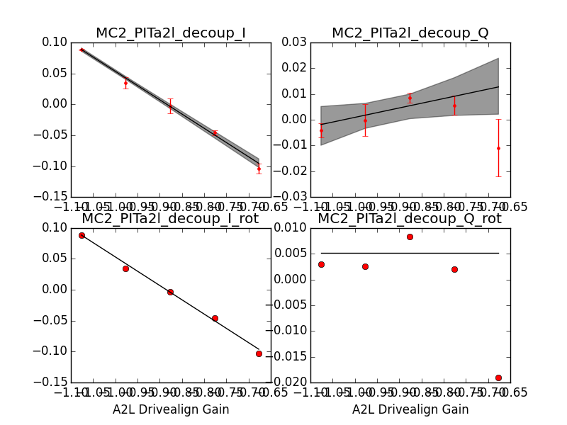
My attempt at balancing MC2 M3 using pringle injection (alog 42888) was somewhat unsatisfactory even though the apparent coil balance was done at sub-% level as there's a phase component that I cannot kill by simply balancing coils. Being pringle, that shouldn't be the case. Electronics zeros/poles in different channels are probably only at or somewhat better balanced than % level anyway, but the question is, are we deceiving ourselves by compensating for a large unknown bogus non-mechanical coupling by "balancing" the coils (first attachment)?

Details:

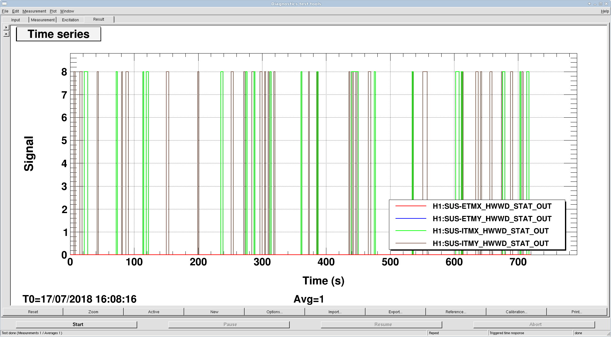
While PSL was down, I measured coupling from all OSEM M2 and M3 output in HAM3 to all sensors in HAM3 that are used for control purpose, i.e. QPDs and top OSEMs. (For the ease of looking at signals, MC CM board was set as if MC was locked at 10W, and MC2 TRANS SUM offset was increased (and I forgot to set it back, which was later found by Jenne) ).

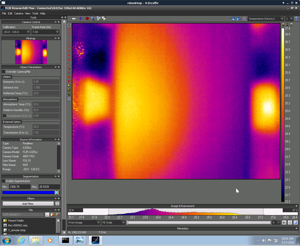
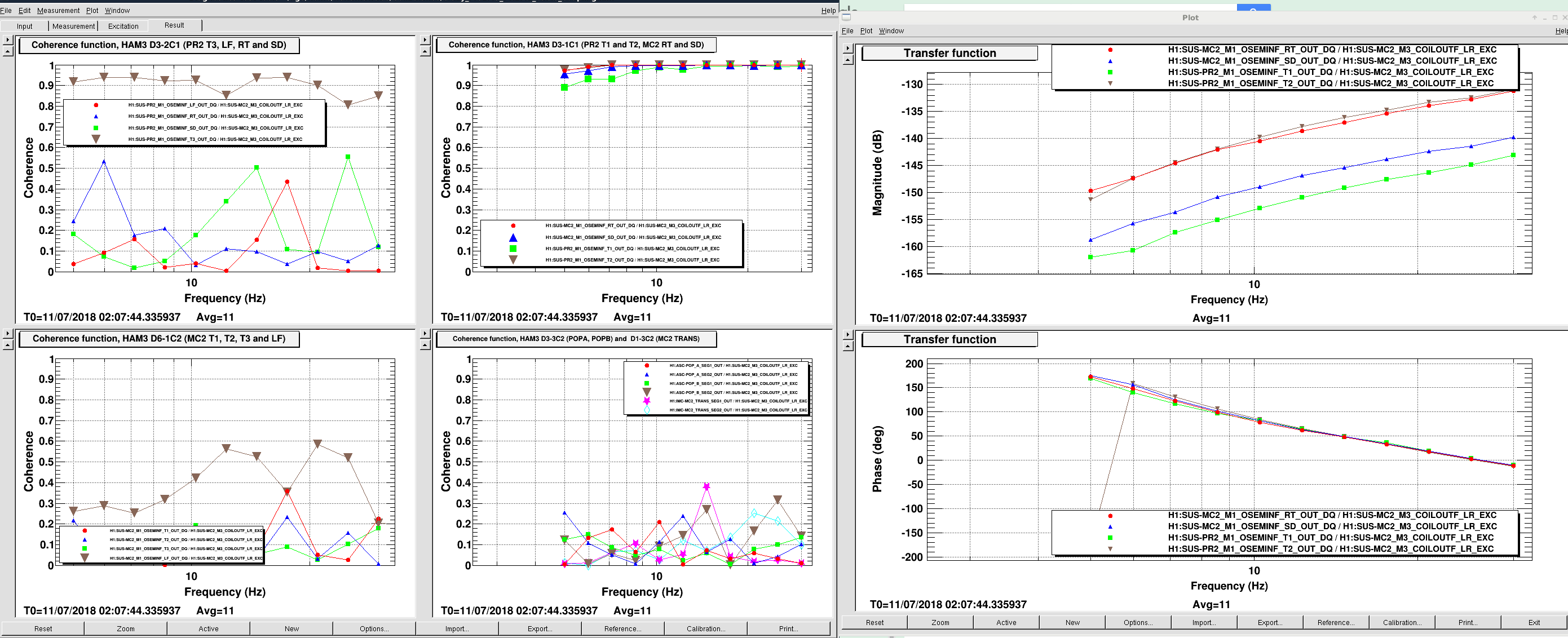
Four specific top OSEM sensors on the same cable (MC2 M1 RT and SD as well as PR2 M1 T1 and T2) were found to be particularly sensitive to other OSEM drives, and it's apparent that this is electronics coupling, not mechanical, from the shape of the transfer function as well as the fact that shaking of MC2 is sensed by PR2 (e.g. 1st attachment, an example of the transfer function from MC2 M3 single coil excitation to all relevant sensors). These couplings mostly show up as L and Y and SD bogus signal in MC2 M1 due to RT and SD sensitivity, P and V and R bogus signal in PR2 M1 due to T1 and T2.

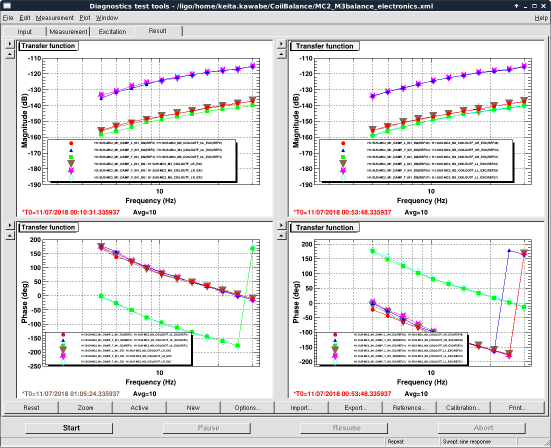
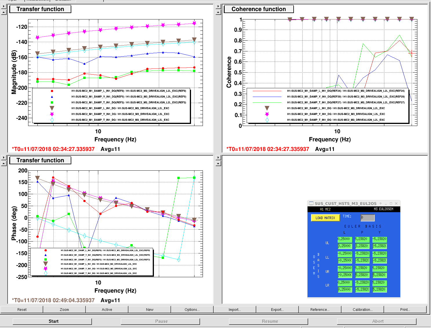
There's not much difference between electronics coupling from UL, LL, UR and LL drive OUTPUT (not input) to any affected sensor. In the second attachment, phase is measured against input (not output) of coil out filter, and therefore the measured phase is flipped between [UL, LR] (left plots) and [UR, LL] (right plots) pairs. This means that the coupling from L, P and Y drive are much weaker than from pringle drive because of cancellation in coil pairs. In the third attachment, low-coherence traces are with L drive, high coherence traces are with pringle drive with the same amplitude excitation.

I put 9Hz notches in MC2 M1 L and Y damp filters, repeated the pringle injection as in alog 42888 with the best apparent balance so far and measured the coupling from pringle to MC2 TRANS YAW (which is a measure of PIT balance) and IMC_L with notches (red, green) and without (blue, black). The power was only 2.6W instead of 10 this time, so S/N is worse. Anyway I don't see any change for IMC_L. For YAW error the amplitude didn't change but the phase change from ~100 deg to ~50. So the impact was not entirely negligible for YAW, and we should be able to minimize the coupling further. But since the amplitude didn't change much if at all, it doesn't sound to me as if this would be a real problem, now we're talking about sub-% level residual due to something other than bogus coupling, e.g. electronics components imbalances,

BTW something*10^-3 is about two orders of magnitude larger than the HSTS model suggests for M3 pringle to YAW, though. I plugged measured electronics coupling from MC2 M3 pringle excitation to MC2 M1 Y into TF model from M1 Y drive to M3 Y motion in HSTS model (4th attachment orange circles) and compared against M3 Y drive to M3 Y motion (blue trace). It seems like orange circles are about 5 orders of magnitude smaller than the blue trace, not 3 orders. I don't know what to tell from this.

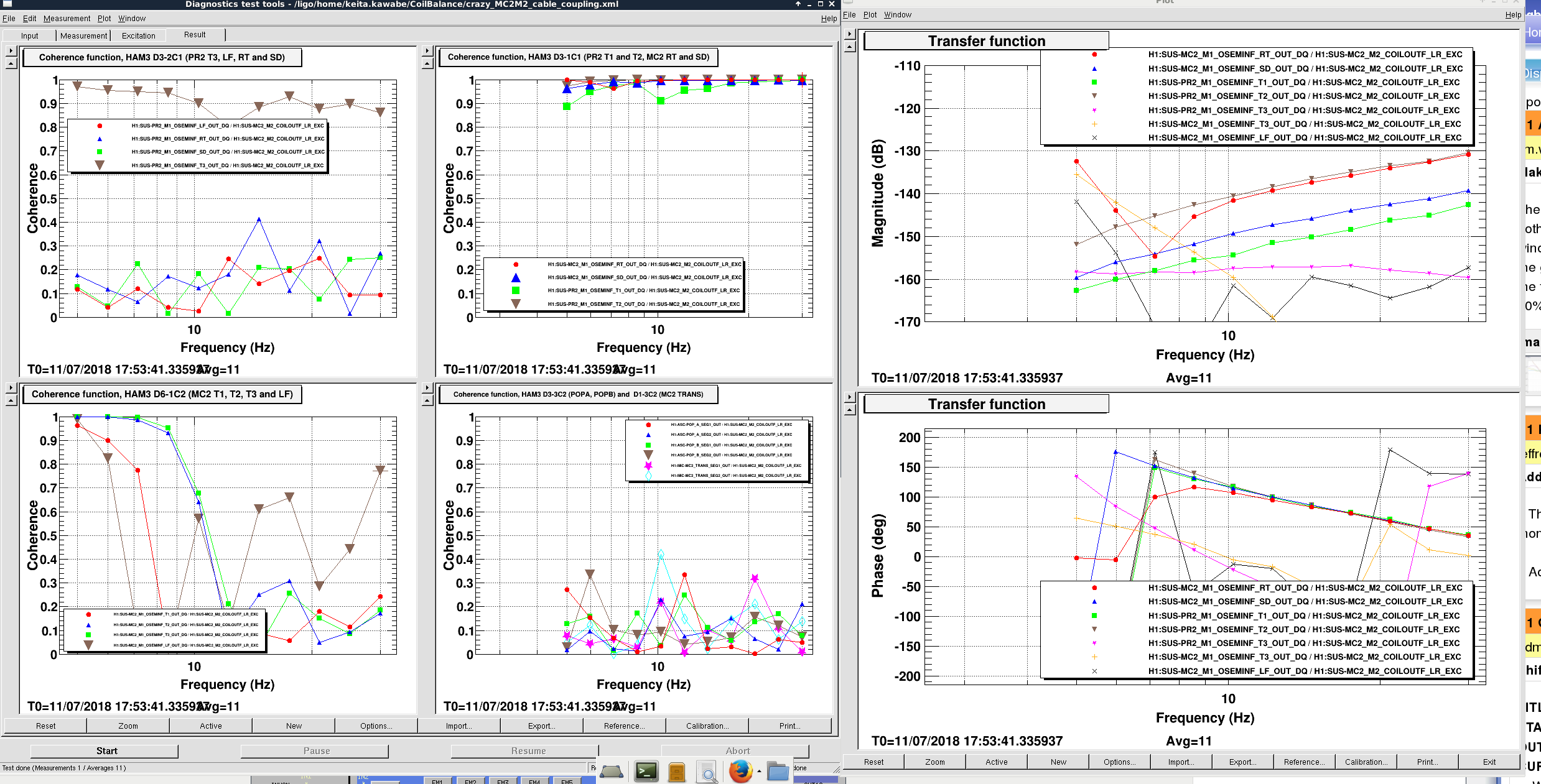
For M2 pringle, you start to see what seems like a legit mechanical coupling superimposed with bogus coupling in some of the M1 sensors below 10Hz (last attached).

Images attached to this report
H1 SUS (CDS, ISC)
jeffrey.kissel@LIGO.ORG - posted 14:48, Monday 16 July 2018 (42922)
QUAD R0, L1, and L2 Actuation Gone Awry Since Extra Violin Mode Damping Filters Installed
J. Kissel, S. Aston

Just in case people were not aware, after the recent install of an expansion pack of violin mode damping filters on the QUADs (see LHO aLOG 42752, ECR E1700286, and IIET ticket 8759), Stuart and I have identified that this some how has insidiously interacted with the binary I/O switching of the coil drivers, see LLO aLOGs 39653 and 39717.

I plan to revert violin mode filter expansion code tomorrow, but that means for now (and since July 3rd 2018) we haven't had truly functional R0, L1 (UIM), or L2 (PUM) actuation on the Test Mass suspensions (QUADs). To be explicit, this affects all QUADs: H1 SUS ITMX, H1 SUS ITMY, H1 SUS ETMX, and H1 SUS ETMY. Attached is the screenshot of how it manifests: a *few* of the coil driver's TEST/COIL enable switches are pushed to TEST, so that the analog input to that driver channel is a terminated resistor, a la L1200193 instead of the requested DAC signal.

I'm happy to revert sooner if we feel it's needed, but the crowd in the control room at the moment, didn't think it was necessary to accelerate the revert faster than tomorrow.

You can track the bug and hopefully its fix via the new IIET Ticket 11066.
Images attached to this report
H1 SEI (PEM)
hugh.radkins@LIGO.ORG - posted 13:38, Monday 16 July 2018 (42921)
LHO End Station HEPI Pumps Off with 0U3 error on VFD causal to Mainmon Spike

The Pump station faults over the weekend,--aLog 42905, corresponds to a glitch seen on the H1:PEM-EY_MAINSMON_EBAY_QUAD_SUM_DQ channels, see the attached plot..  A spike in the supply can cause the VFD to sense an excessive voltage and the VFD zeros its output and goes into OU3 fault.

Bringing these pumps back on line was standard but did require access inside the enclosure to press the reset button.

FRS 11093

Images attached to this report
LHO General
david.barker@LIGO.ORG - posted 12:38, Monday 16 July 2018 (42920)
CP4 Dewar channels removed from cell phone alarms

From a cell text message, Chandra requested that CP4 Dewar channels be removed from the cell phone alarms system. I did this today and restarted the system.

svn di h0ve_configuration.xml
Index: h0ve_configuration.xml
===================================================================
--- h0ve_configuration.xml    (revision 4686)
+++ h0ve_configuration.xml    (working copy)
@@ -298,35 +298,7 @@
   <Contact address="cromel@caltech.edu"                 hot="5"  cool="2" description="E:Chandra Romel"></Contact>
   <Contact address="jjones@caltech.edu"                 hot="5"  cool="2" description="E:Jeff Jones"></Contact>
 </Channel>
-<!-- CP4 -->
-<Channel name="H0:VAC-MY_CP4_LT255_DEWAR_LEVEL_PCT" low="1.5e+01" high="9.9e+01" description="CP4 Dewar LN2 Level">
-  <Contact address="5094380824@vtext.com" hot="15" cool="5" description="C:Richard McCarthy"></Contact>
-  <Contact address="5094380826@vtext.com" hot="15" cool="5" description="C:David Barker"></Contact>
-  <Contact address="5094380828@vtext.com" hot="15" cool="5" description="C:Gerardo Moreno"></Contact>
-  <Contact address="5093080755@vtext.com" hot="15" cool="5" description="C:Kyle Ryan"></Contact>
-  <Contact address="5094388939@vtext.com" hot="15" cool="5" description="C:Chandra Romel"></Contact>
-  <Contact address="5094380823@vtext.com" hot="15" cool="5" description="C:Jeff Jones"></Contact>
-  <Contact address="mccarthy_r@ligo-wa.caltech.edu"     hot="5"  cool="2" description="E:Richard McCarthy"></Contact>
-  <Contact address="barker@ligo-wa.caltech.edu"         hot="5"  cool="2" description="E:Dave Barker"></Contact>
-  <Contact address="gmoreno@caltech.edu"                hot="5"  cool="2" description="E:Gerardo Moreno"></Contact>
-  <Contact address="kryan@caltech.edu"                  hot="5"  cool="2" description="E:Kyle Ryan"></Contact>
-  <Contact address="cromel@caltech.edu"                 hot="5"  cool="2" description="E:Chandra Romel"></Contact>
-  <Contact address="jjones@caltech.edu"                 hot="5"  cool="2" description="E:Jeff Jones"></Contact>
-</Channel>
-<Channel name="H0:VAC-MY_CP4_LT255_DEWAR_LEVEL_PCT_ERROR" low="-5.0e-01" high="1.0e+00" description="CP4 Dewar LN2 Level ERROR">
-  <Contact address="5094380824@vtext.com" hot="15" cool="5" description="C:Richard McCarthy"></Contact>
-  <Contact address="5094380826@vtext.com" hot="15" cool="5" description="C:David Barker"></Contact>
-  <Contact address="5094380828@vtext.com" hot="15" cool="5" description="C:Gerardo Moreno"></Contact>
-  <Contact address="5093080755@vtext.com" hot="15" cool="5" description="C:Kyle Ryan"></Contact>
-  <Contact address="5094388939@vtext.com" hot="15" cool="5" description="C:Chandra Romel"></Contact>
-  <Contact address="5094380823@vtext.com" hot="15" cool="5" description="C:Jeff Jones"></Contact>
-  <Contact address="mccarthy_r@ligo-wa.caltech.edu"     hot="5"  cool="2" description="E:Richard McCarthy"></Contact>
-  <Contact address="barker@ligo-wa.caltech.edu"         hot="5"  cool="2" description="E:Dave Barker"></Contact>
-  <Contact address="gmoreno@caltech.edu"                hot="5"  cool="2" description="E:Gerardo Moreno"></Contact>
-  <Contact address="kryan@caltech.edu"                  hot="5"  cool="2" description="E:Kyle Ryan"></Contact>
-  <Contact address="cromel@caltech.edu"                 hot="5"  cool="2" description="E:Chandra Romel"></Contact>
-  <Contact address="jjones@caltech.edu"                 hot="5"  cool="2" description="E:Jeff Jones"></Contact>
-</Channel>
+<!-- CP4 Dewar alarms removed after decommissioning of the pump. D Barker LHO 16jul2018 -->
 <!-- CP5 -->
 <Channel name="H0:VAC-MX_CP5_LT305_DEWAR_LEVEL_PCT" low="1.5e+01" high="9.9e+01" description="CP5 Dewar LN2 Level">
   <Contact address="5094380824@vtext.com" hot="15" cool="5" description="C:Richard McCarthy"></Contact>


LHO VE
kyle.ryan@LIGO.ORG - posted 12:33, Monday 16 July 2018 - last comment - 16:54, Monday 16 July 2018(42919)
Opened Large Gate Valves to facilitate IFO commissioning

Kyle, Gerardo

The commissioners requested that both arms be opened today -> We confirmed that all viewport work was complete.  RGA scans were then taken of the CS and X-end and a visual inspection of the viewports in the LVEA and at the X-end was made prior to opening. 

Comments related to this report
kyle.ryan@LIGO.ORG - 16:54, Monday 16 July 2018 (42924)

Scans from this morning are now included.

NOTE: The CS scan is of the Vertex+YBM+XBM combined volumes while being pumped by CP1, CP2, IP2, IP3, IP4, IP5, NEG1, NEG2, NEG3 and CP1_IP and just prior to being exposed to the arms.  The Xend scan is of the X-end volume while being pumped by the turbo and the NEG5 and just prior to being exposed the CP8+arm.

Non-image files attached to this comment
Displaying reports 46481-46500 of 88171.Go to page Start 2321 2322 2323 2324 2325 2326 2327 2328 2329 End