Jeff K., Edgard, Hang
Today we continued to implement the ISI to top mass (M0) FF and the results looked promising.
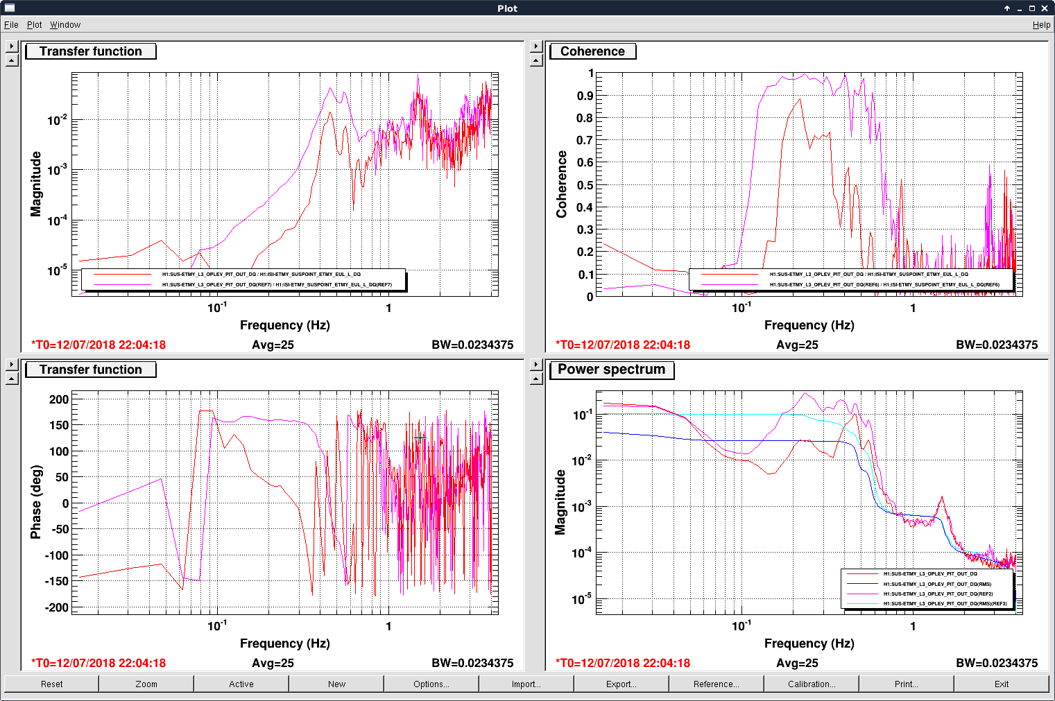
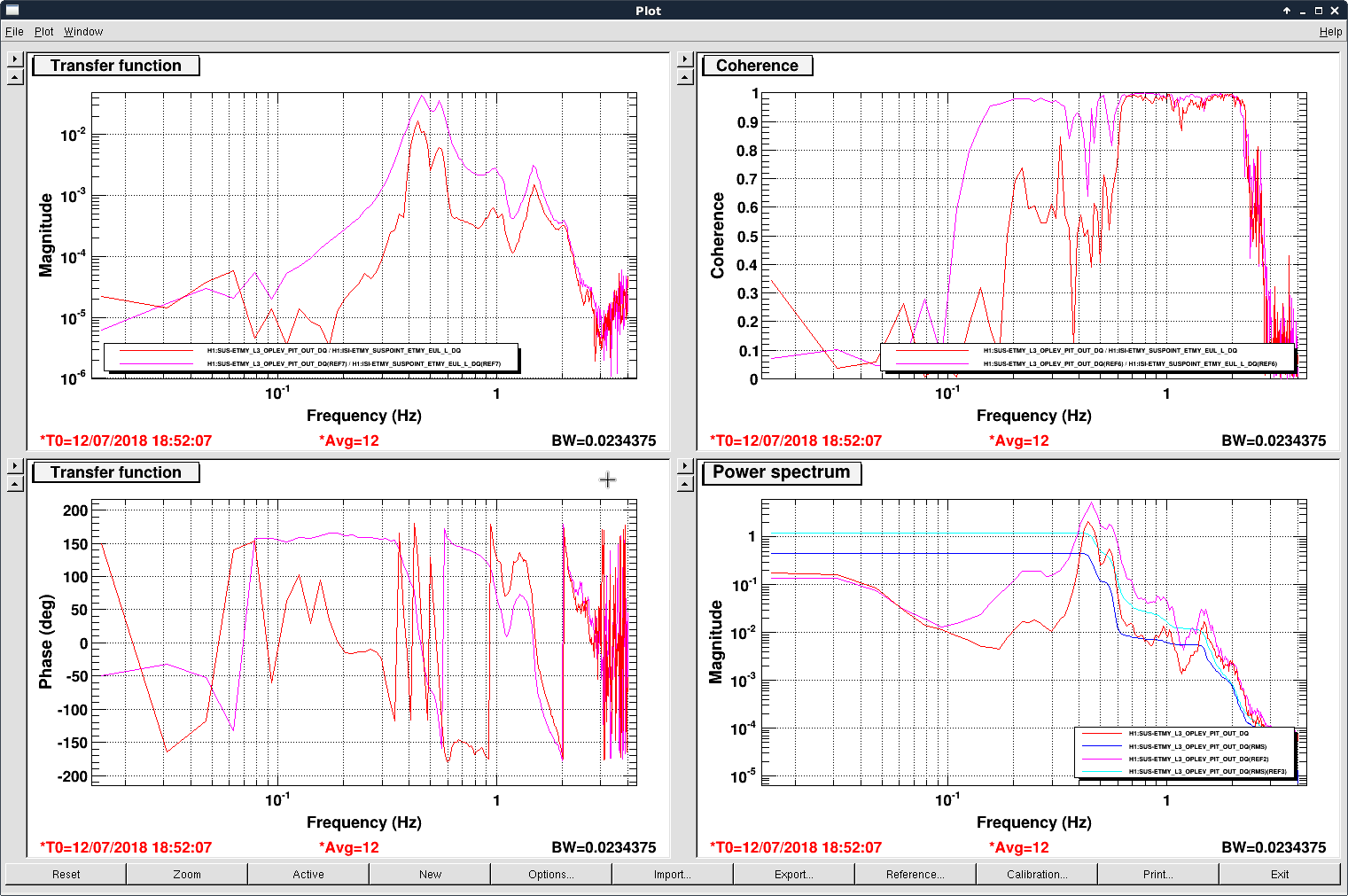
In the first plot we showed the ISI_SUSPOINT_L to ETMY L3 oplev pitch transfer function (left panels), coherence (top-right), and oplev asd (bottom-right). The pink and cyan curves were without the ISI2M0 FF and the red curves with the FF on. A broad band reduction in the pitch motion from 0.1 Hz to 1 Hz was achieved with the rms pitch motion reduced by a factor of ~ 2.5.
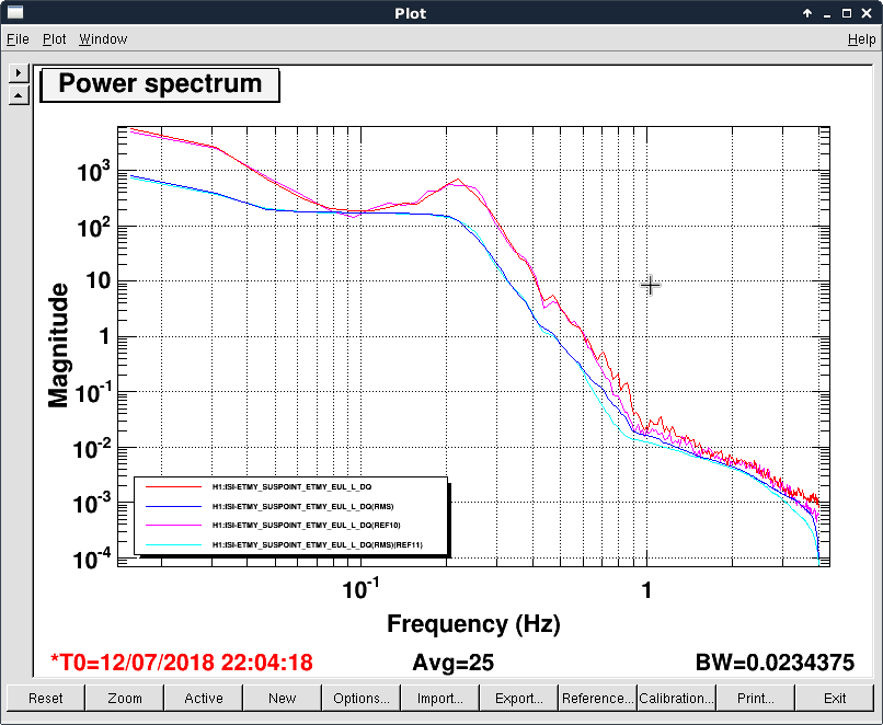
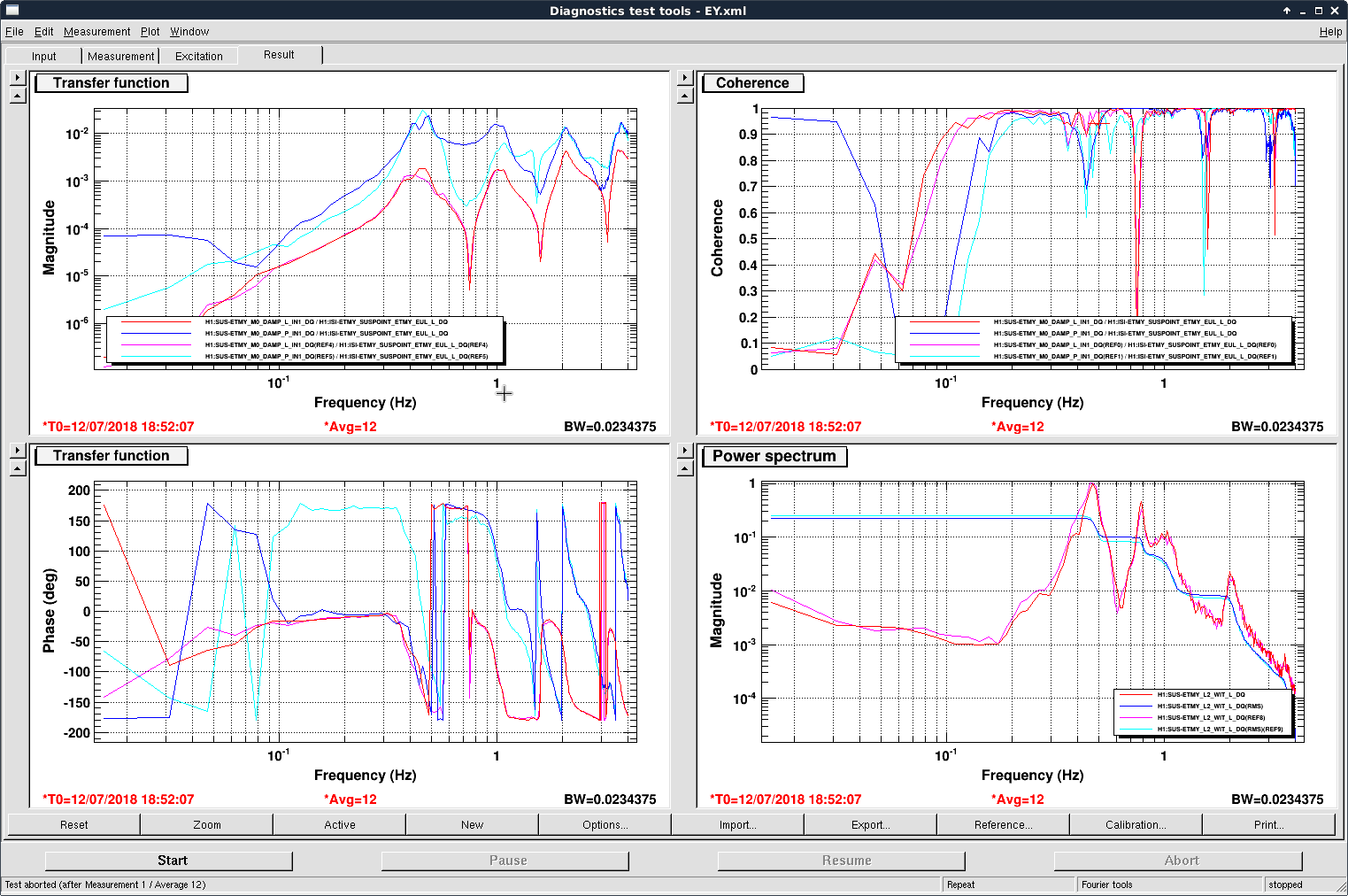
The measurement was done using the passive data (i.e. excitation from the sei motion). To make sure the rms between measurements were comparable we also showed the ISI suspoint asd in the second plot. No significant difference between the SEI motion was noticed, and thus the reduction achieved should be real.
We will try to use some interferometric data to validate the result when the beam is back, and test the robustness of the FF filter over time in the future.
=====================================================================
Details:
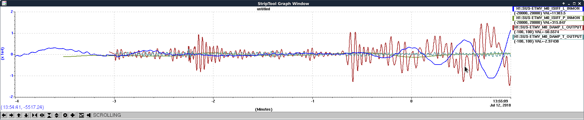
We first tried to use the scalar FF (LHO:42866) to simultaneously reduce the M0 length and pitch motion. After made sure that we measured the M0 motion relative to the ground instead of ISI, the measured FF coefficients were consistent with the prediction in that they were essentially constants in the low freq band. However, after we turned on the FF, somehow we created an unstable feedback loop.
See the third image. The FF was turned on at around -0.7 min in the strip tool. First we excited the local damping ctrl, presumably due to that as we tried to stabilize the M0 to the ground, we intentionally created differential motion between M0 and ISI which made the local damping loops unhappy. Moreover, somehow the suspoint input started to oscillation and grew exponentially... Somehow we formed a feed back loop in the SEI chain...
Instead, we tried an alternative approach. Since we were mostly interested in reducing the L3 stage pitch motion, we directly measured the (SUS-ETMY_SUSPOINT_ETMY_EUL_L_DQ --> SUS-ETMY_L3_OPLEV_PIT_OUT_DQ) transfer function, and FF the negative of this TF to the M0 P drive (using the SUS-ETMY_M0_ISIFF_L2P filter module). Specifically, the filter we put in was
- (SUS-ETMY_SUSPOINT_ETMY_EUL_L_DQ --> SUS-ETMY_L3_OPLEV_PIT_OUT_DQ) / (SUS-ETMY_M0_TEST_P_OUT --> SUS-ETMY_L3_OPLEV_PIT_OUT_DQ),
(which was the standard way of designing FF filters), and the resultant improvement was shown in the first attached image with passive data.
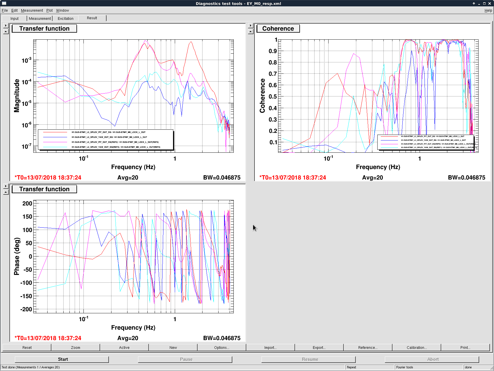
For completeness, we also actively shook the ISI so that we could see the performance up to 2 Hz. Again a broadband reduction was achieved.
The potential drawback for this new scheme (stabilizing only L3 pitch) relative to simultaneously stabilizing M0 length and pitch was that it could inject extra longitudinal noise at low frequencies. This would not be an issue in full lock as the longitudinal loops have sufficient bandwidth to suppress this noise, yet it might affect the lock acquisition. To address this issue we looked at the L2 stage osem length response (without the main or the ALS beam we could not extract L3 stage's length motion unfortunately). The result was shown in the last figure's bottom right panel. Again red and blue curves were FF off and pink and cyan ones FF on. The L2 L asd looked essentially the same thus hopefully our FF would not be an issue for the L3 stage also.