Jeff K., Jim, Hang
We tried to implement the ISI suspoint to top mass feeding forward installed by Jeff yesterday (LHO:42851; for more details, see the note by Edgard T1800301).
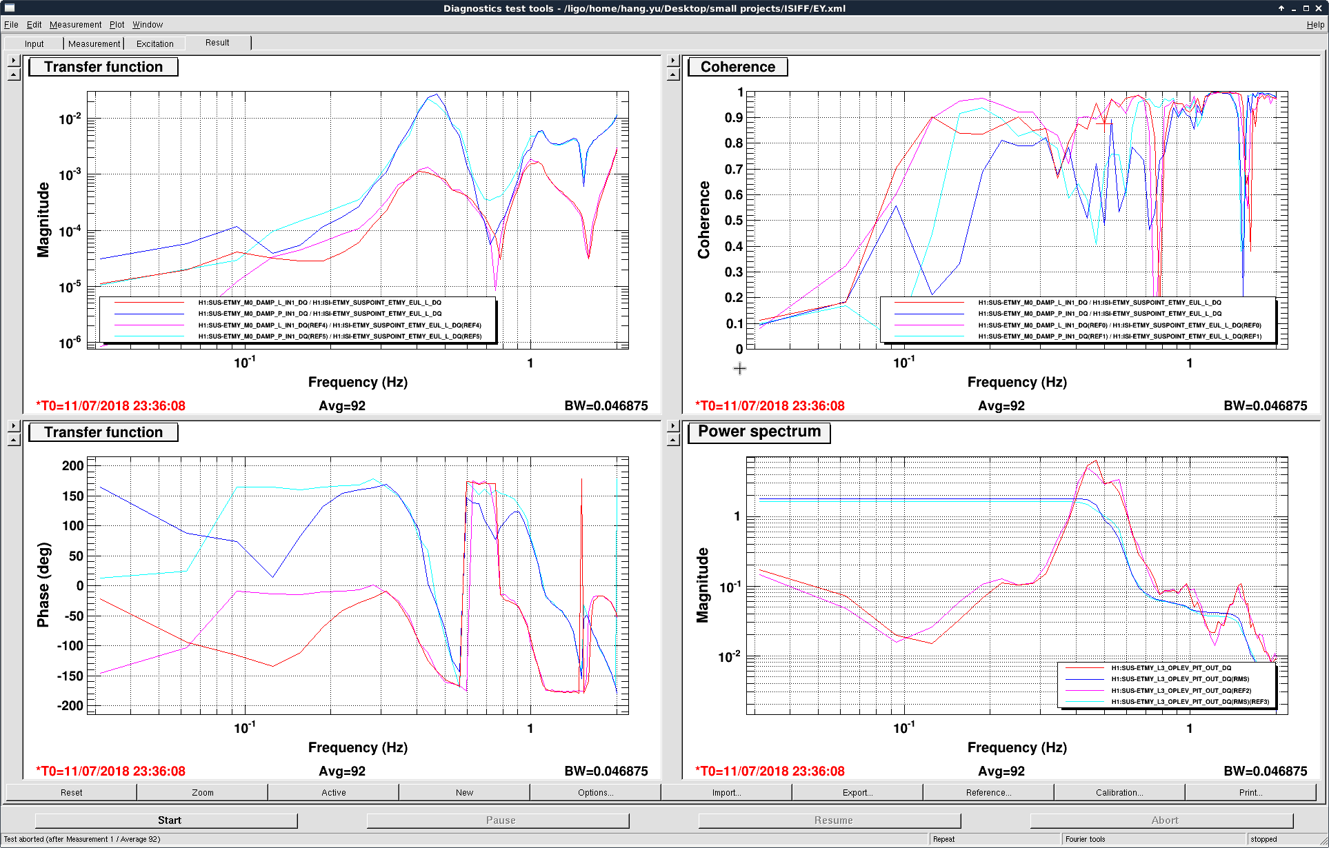
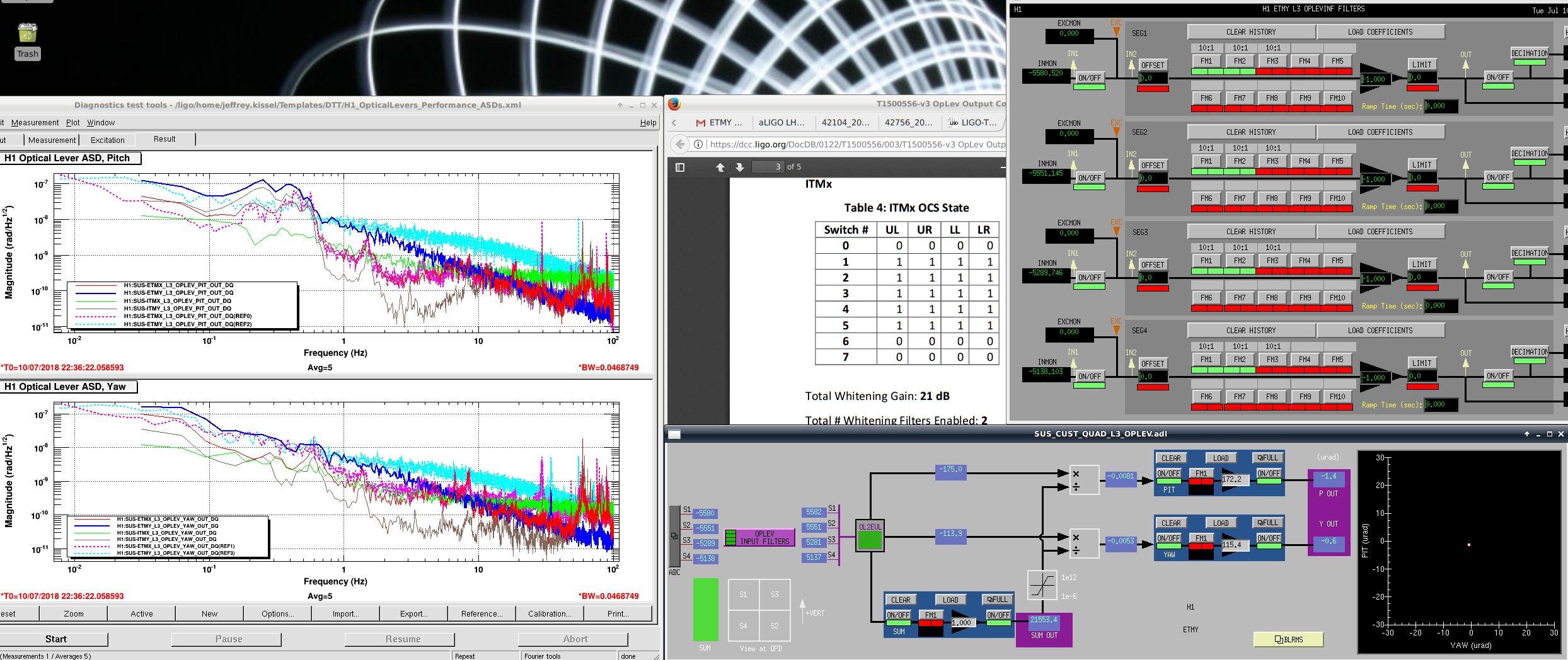
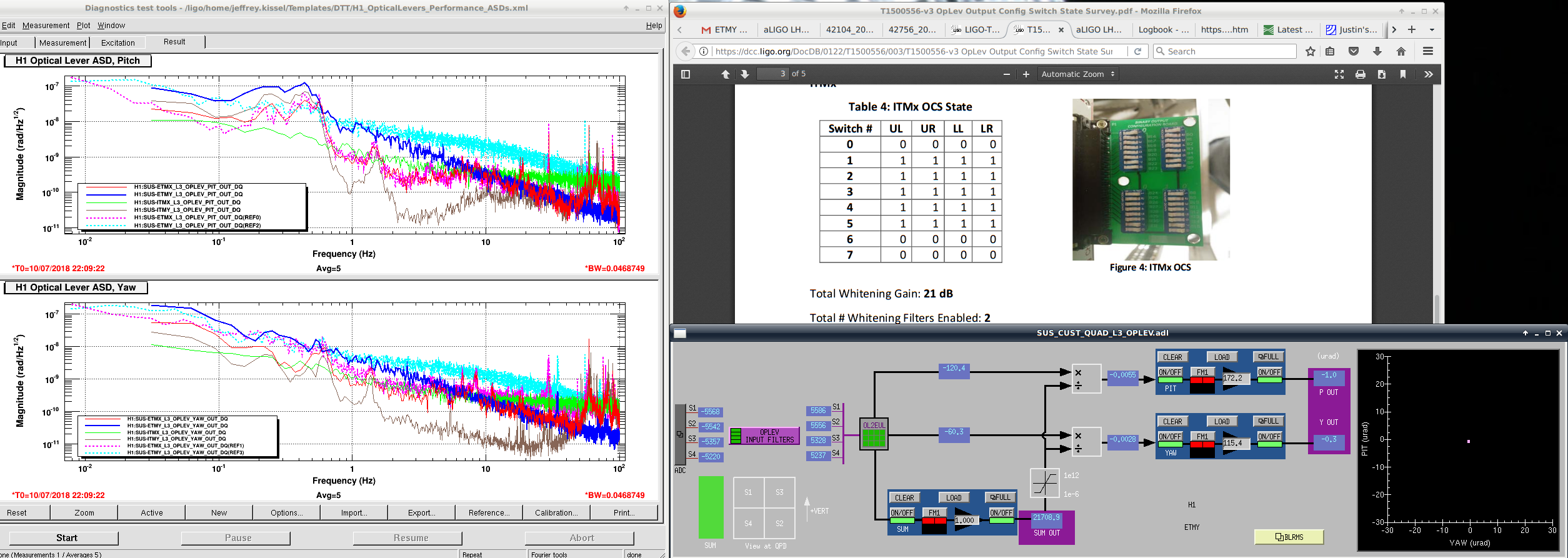
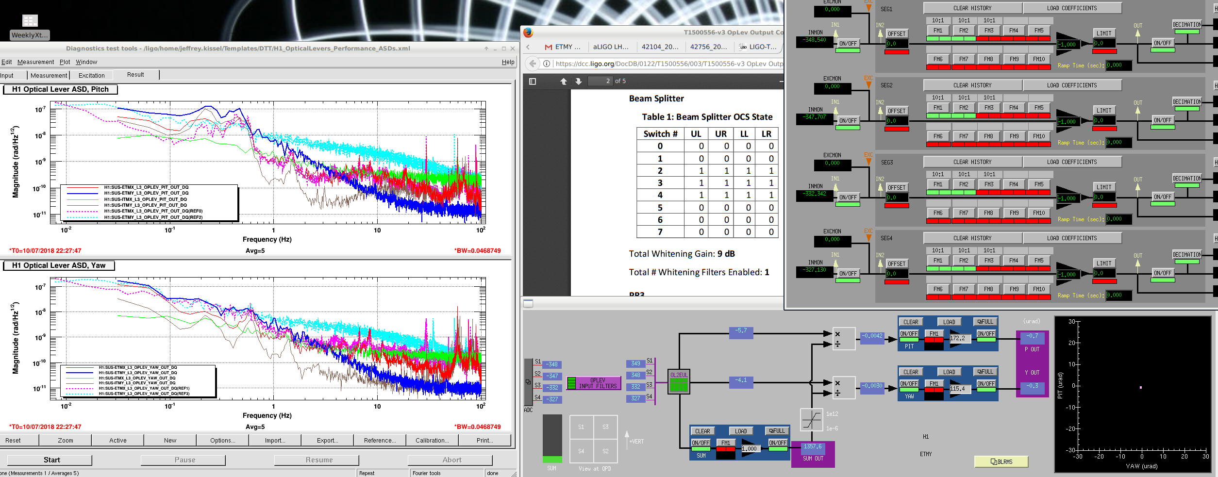
Using scalar FF coefficients for ISI-L_2_M0-L and ISI-L_2_M0-P, we were able to achieve some reduction of the M0 L & P motions at ~ 0.2 Hz (the freq which we tuned the FF for). See the first attached image.
In the measurement we excited the EY ISI second stage with a broadband white noise and then measure the SUSPOINT_L to M0_DAMP_L/P_IN1 transfer functions. The pink and cyan curves were WITHOUT FF, and the red and blue ones were with the FF ON.
We can see that the coherence (top-right panel) was reduced at ~ 0.2 Hz for both M0-L and M0-P. The oplev pitch motion (bottom-right) was also reduced at the same frequency (the oplev rms was a bit misleading as we excited the ISI with white noise so the main resonance at ~ 0.5 Hz dominated the rms; in reality the total rms was dominated by the microseismic). We have not yet fine-tuned the coefficients so the performance can be improved in the future.
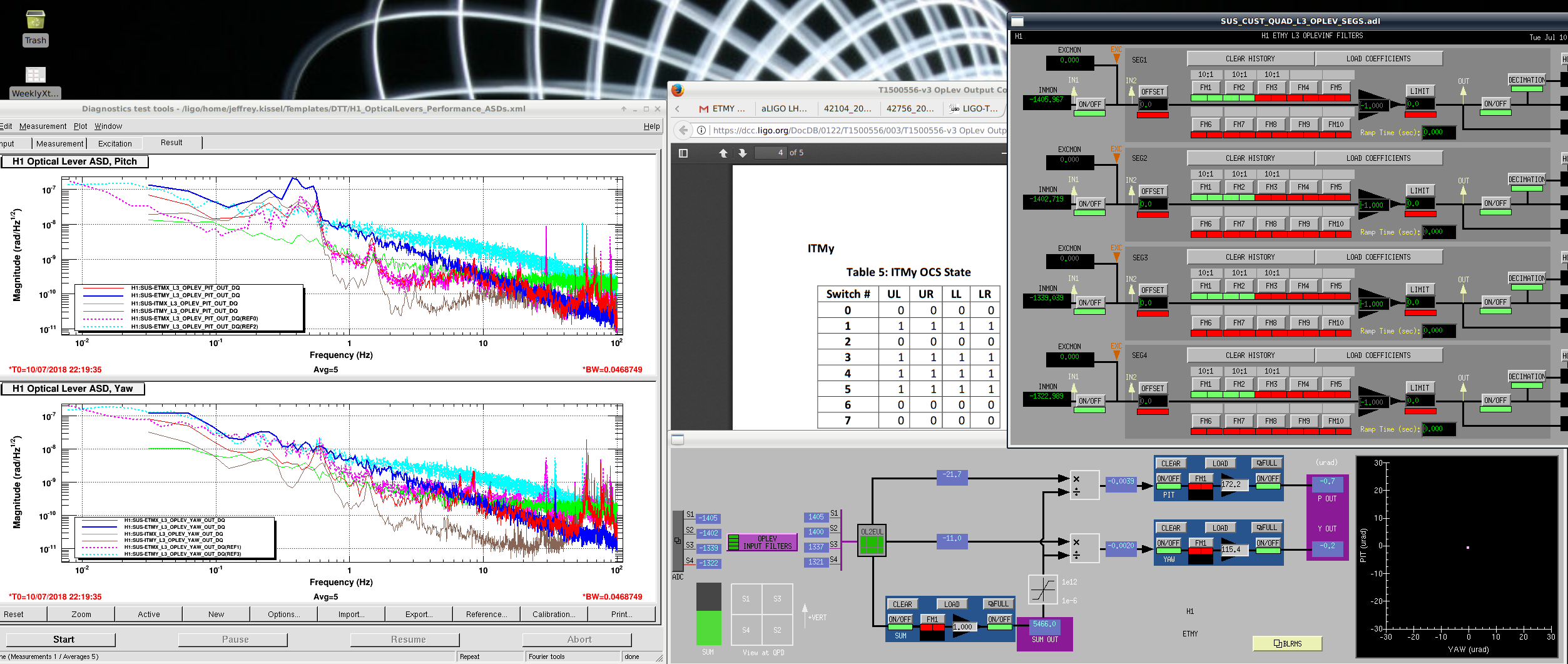
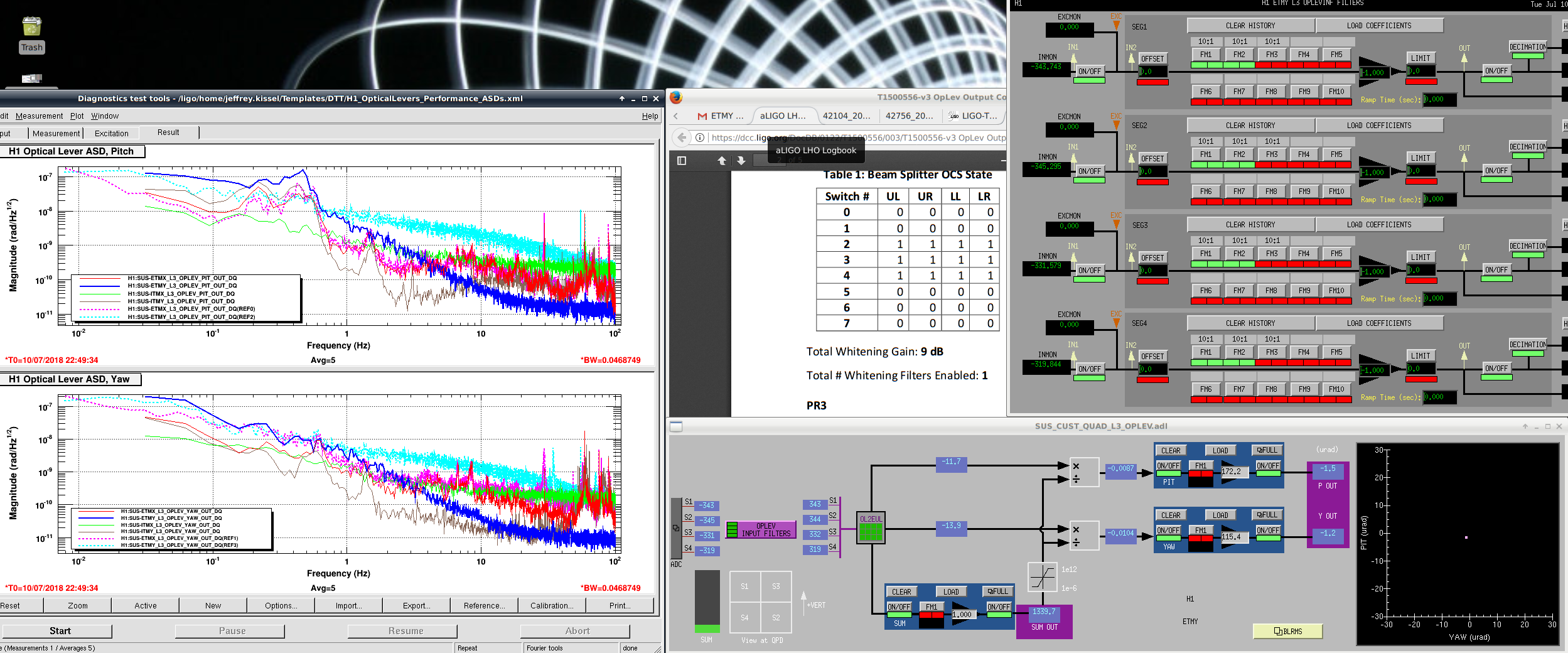
However, we noticed that the optimal FF coefficients appeared to have a strong frequency dependency, and this was what limited our subtraction to a narrow band. This was a bit surprising as we was expecting the coefficients to be essentially a constant according to the model (T1800301). The inferred coefficients based on the measurements were plotted in the third and forth plots, for ISI-L_2_M0-L and ISI-L_2_M0-P, respectively.
====================================================
Details:
Instead of putting in the FF filters based on first principle, we decided to do a completely measurement based FF design.
To do so, we first did 6 measurements:
two for ISI SUSPOINT_ETMY_EUL_L to M0_DAMP_L(P)_IN1, and
four for M0_TEST_L(P) to M0_DAMP_L(P)_IN1.
We denote the ISI drive as d ISI_L and top mass drives as d M0_L(P). The osem sensor responses are denoted by d O_L(P).
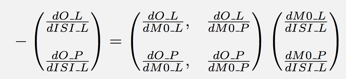
Our goal is to find FF coefficients d M0_L(P) / d ISI_L that satisfies the equation shown in the second attached image (eq_ff_coeff.png). The solutions can be easily obtained from our measurements, and are shown in the third and forth attached images.
Unexpectedly, we saw a strong frequency dependency in those coefficients which was not expected from the first principle calculations.
For now we only put the inferred values at 0.2 Hz, which led to the subtraction results shown in the first image. We will do a more careful measurement to verify the frequency dependence, and if the feature persists we will try to do freq-dependent FF to optimize its behavior.


Keita also in CR and TJ at EX