Ops Shift Log: 07/10/2018, Day Shift 15:00 – 23:00 (08:00 - 16:00) Time - UTC (PT)
State of H1: Unlocked - Commissioning
Intent Bit: Commissioning
Support: N/A
Incoming Operator: N/A
Shift Summary: Maintenance day and commissioning activities across the site.
Activity Log: Time - UTC (PT)
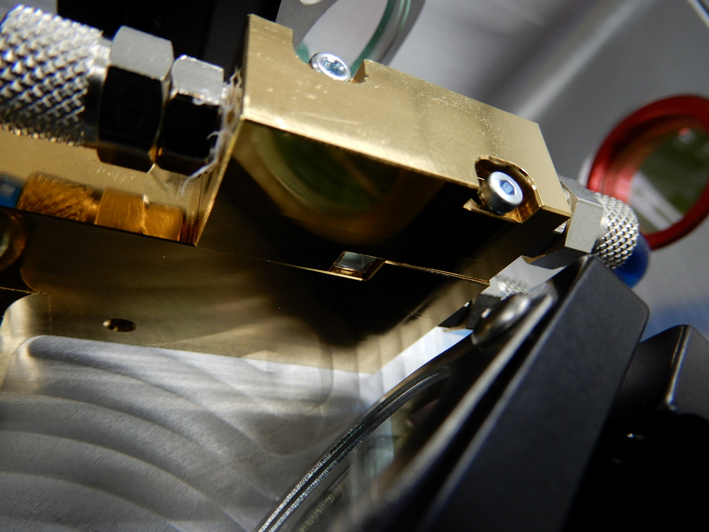
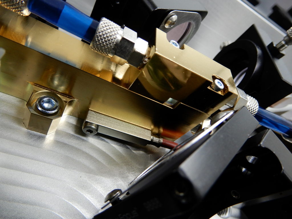
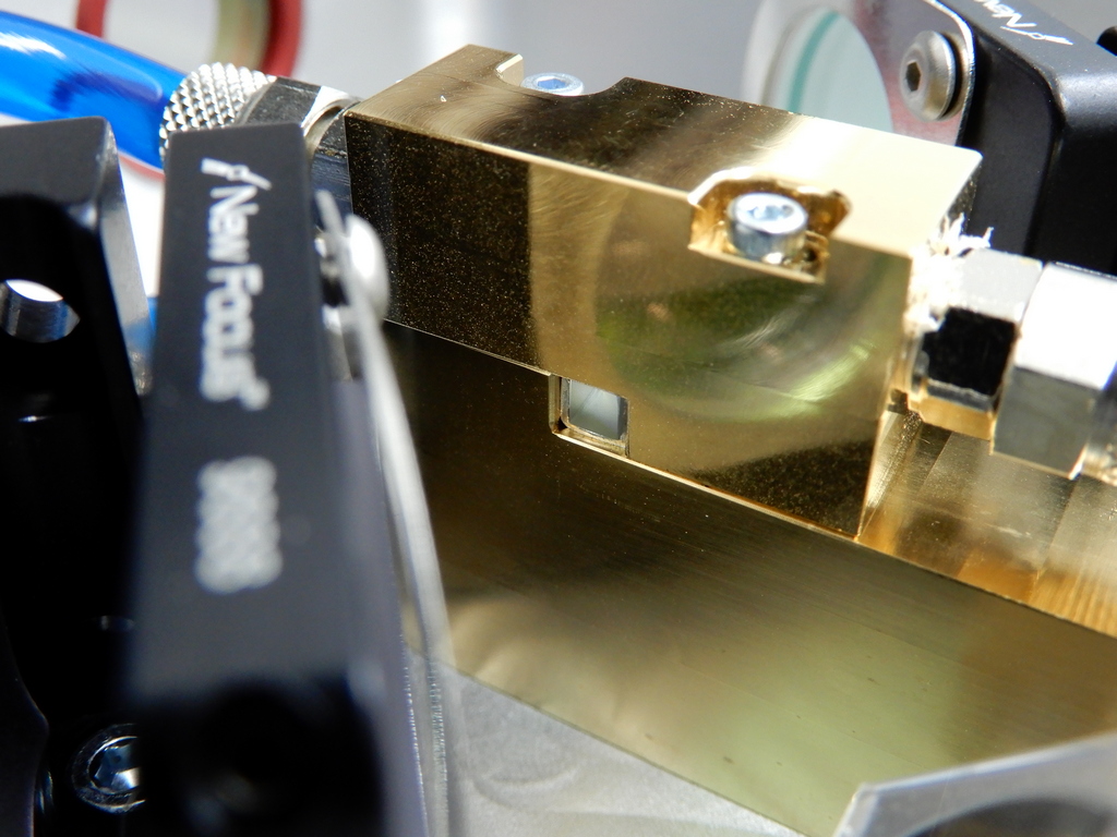
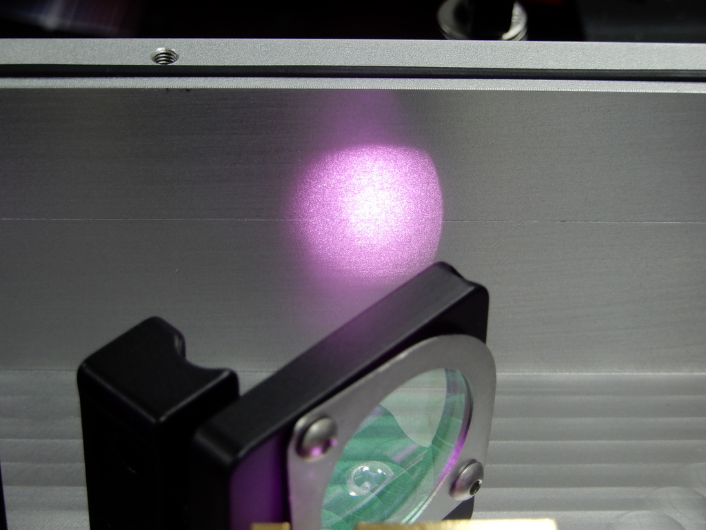
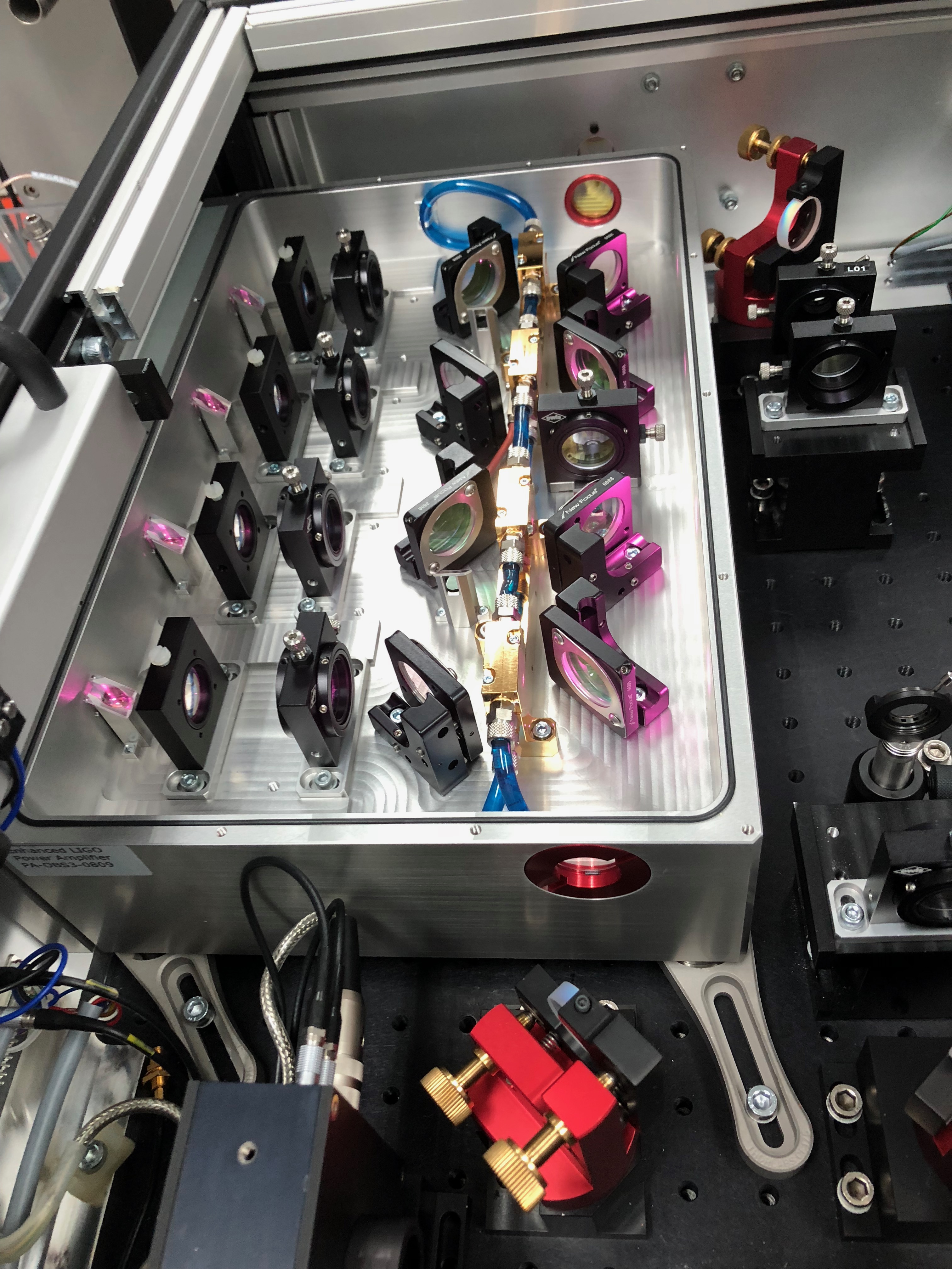
13:05 (06:05) Peter & Richard – Into the PSL Enclosure to work on FE crystal check
14:55 (07:55) Karen – Cleaning in dirty side of VPW
15:00 (08:00) Start of shift
15:17 (08:17) Chris – In the LVEA for monthly equipment checks
15:24 (08:24) Vanessa – Going to End-X
15:38 (08:38) Chris – Finished in LVEA – Going to End stations for same equipment checks
15:55 (08:55) Cintas – On site to service mats
16:02 (09:02) Jason – Going into the PSL
16:13 (09:13) Richard – Out of the PSL Enclosure
16:21 (09:21) Karen – Going to End-Y to clean
16:22 (09:22) Chris – Finished at end stations
16:23 (09:23) Chris – Going into the LVEA to check pest control traps
16:30 (09:30) Peter – Out of the PSL Enclosure
16:33 (09:33) Chris – Out of the LVEA
16:37 (09:37) TJ – Back from End-X
16:41 (09:41) Contractor on site to service Porta-Potty
16:57 (09:57) Norco – On site to deliver N2 to CP1
17:13 (10:13) King Soft – On site to service RO
17:14 (10:14) Norco – On site to deliver N2 to CP2
17:39 (10:39) Mark – Going into the LVEA to park the snorkel lift
17:46 (10:46) Kyle – Going into the LVEA
17:55 (10:55) Karen – Finished at End-Y – Coming back to CS
18:35 (11:35) PSL Crew – Out of the enclosure for lunch
18:50 (11:50) Mark – Out of the LVEA
18:53 (11:53) Contractor on site to service drink machines
18:55 (11:55) Hugh – Going into the CER
19:00 (12:00) Hugh – Out of the CER
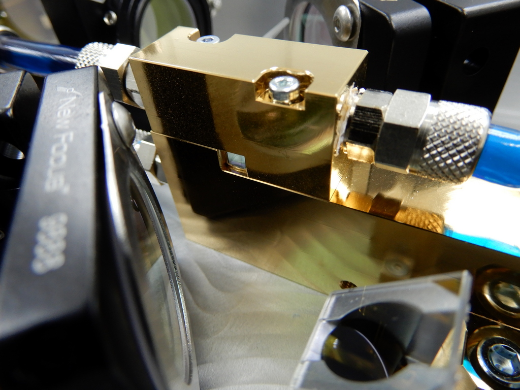
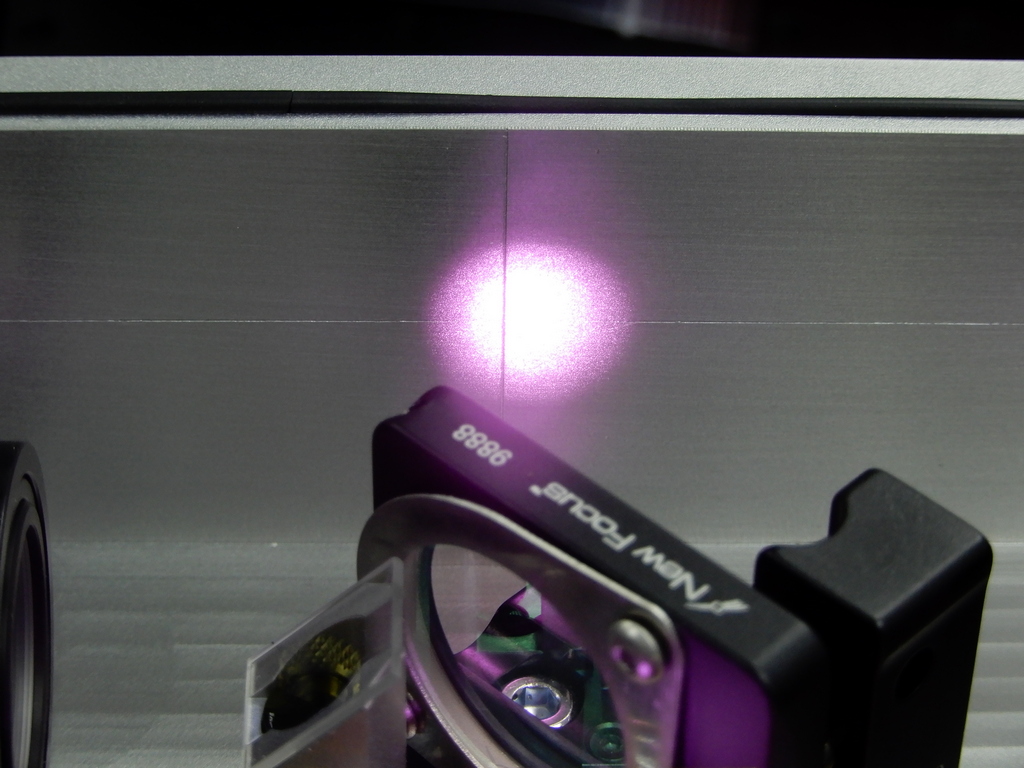
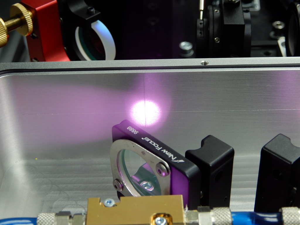
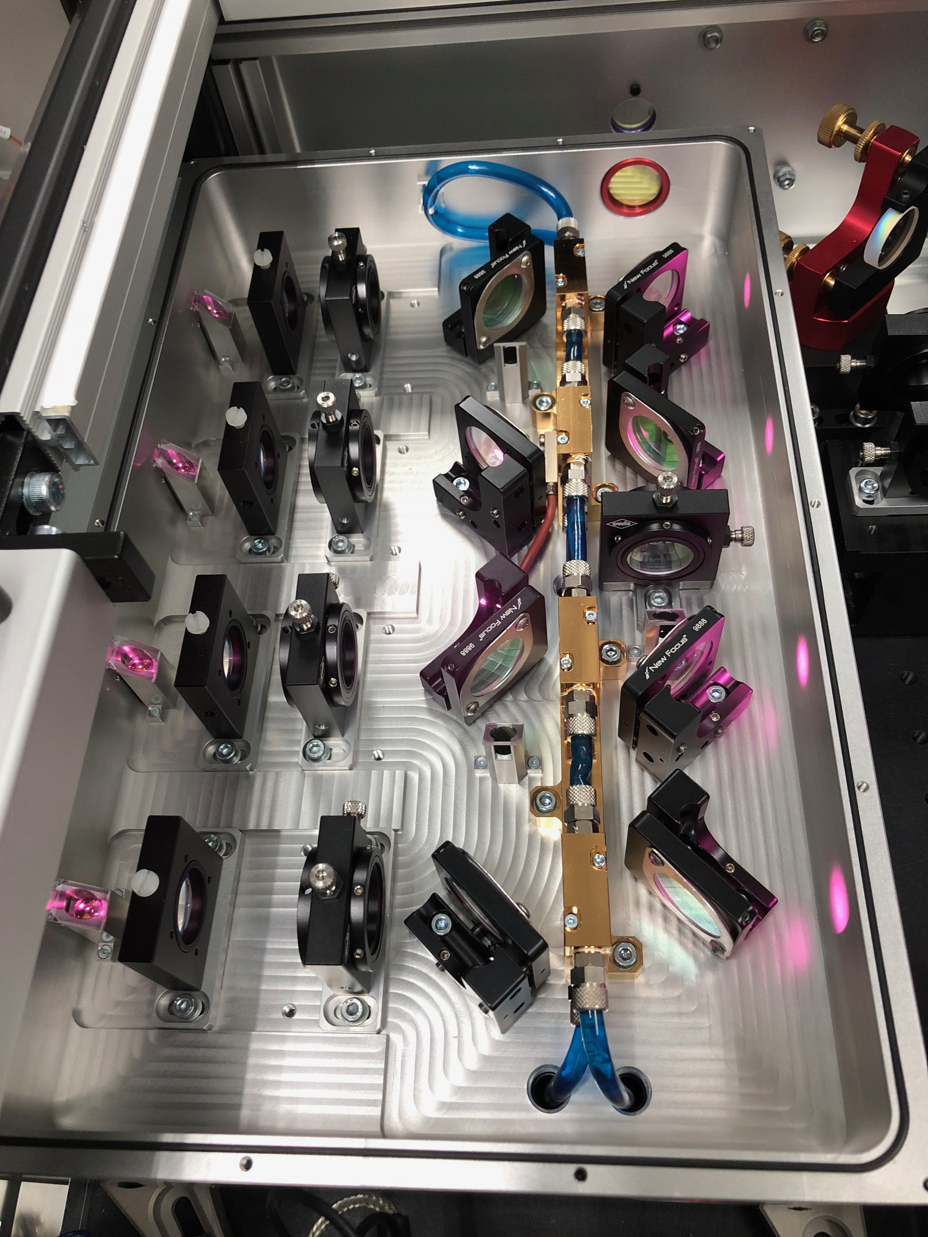
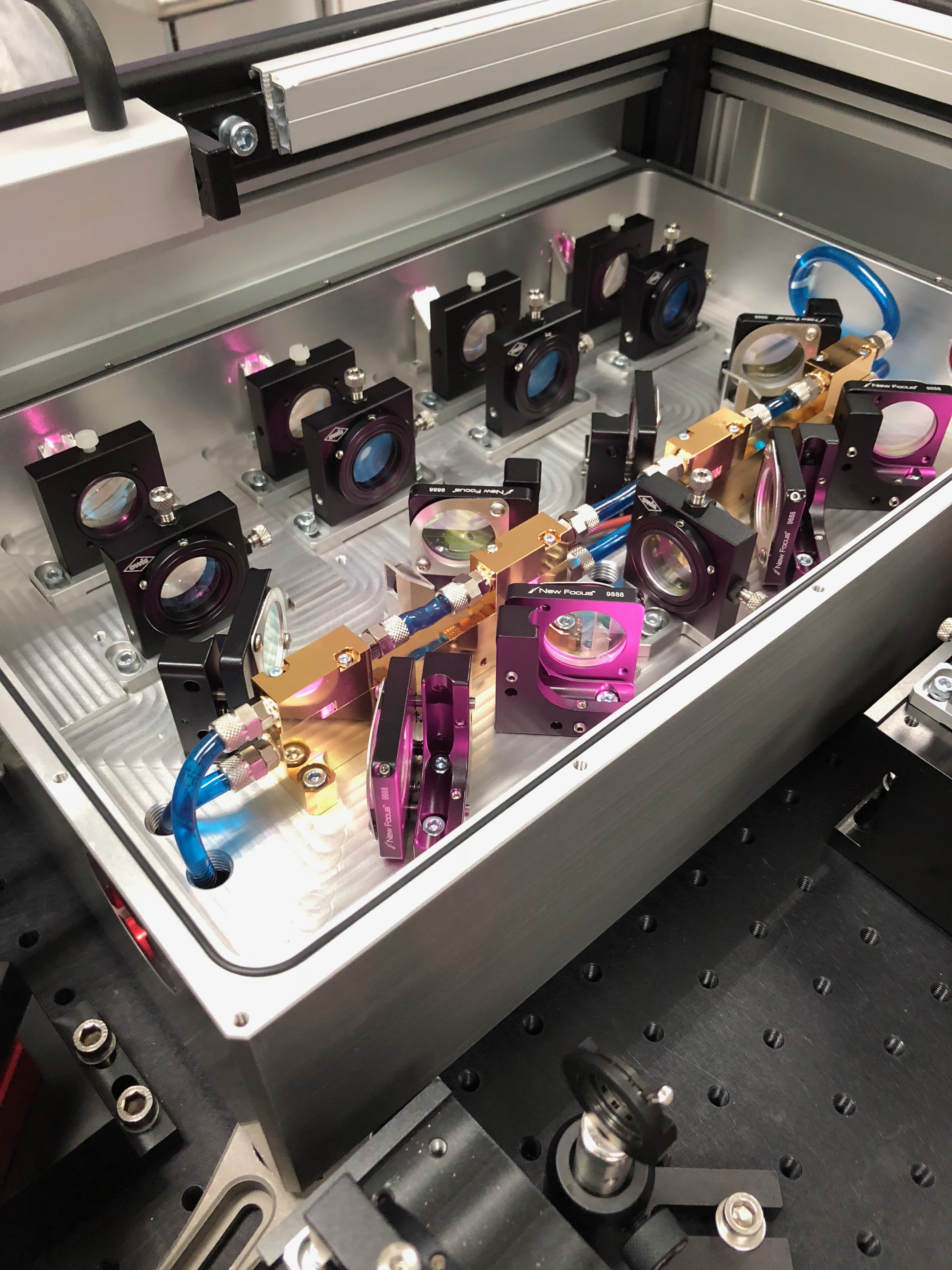
20:22 (13:22) Jason – Going into PSL Enclosure for FE swap
20:38 (13:38) Peter – Going into PSL Enclosure for FE swap
21:40 (14:40) Filiberto – Finished with cable work in the CER (WP #7705)
21:44 (14:44) Filiberto – Going to HAM6 area to pull cables for PEM install (WP #7705)
21:53 (14:53) Robert, Philippe, Kara – Going to HAM2 (IOT2L) to relocate PEM sensors (WP #7707)
23:00 (16:00) End of Shift