[Aidan, Marie, Dan B, Alexei, Keita]
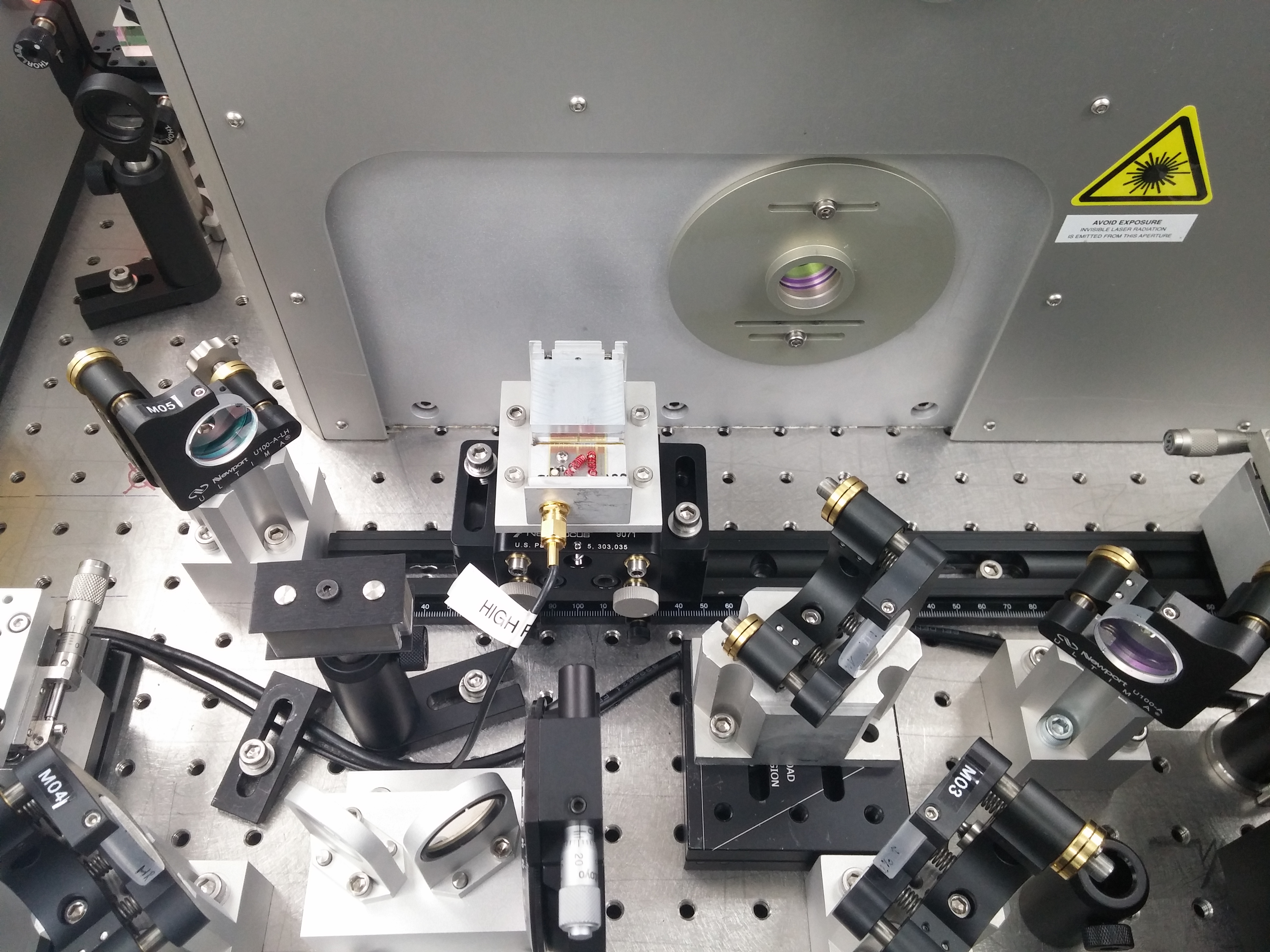
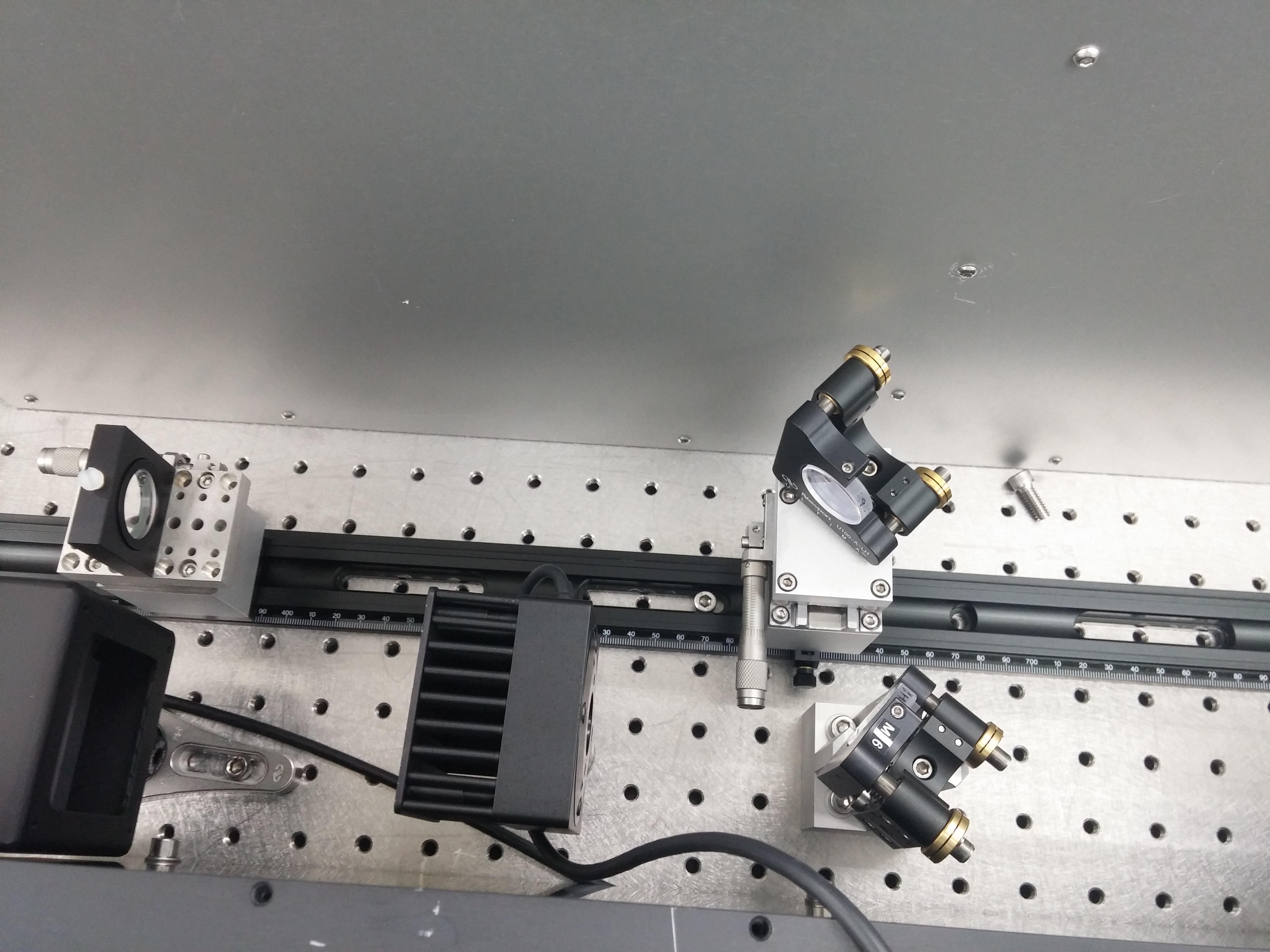
Yesterday morning we realigned the ALS beam into the vacuum system, confirmed it was centered on the TMS QPDs, confirmed it was coming out again and was centered on the in-air WFS and confirmed that it was getting back to the ALS length PD. The two irises installed after the PBS were centered on this ALS beam.
We then aligned the LED beam through the PBS and through the two irises. By carefully fine-tuning this alignment as best we could by eye, we found that there was a return beam coming back to the Hartmann sensor.
The return beam is quite sensitive to alignment. There is a narrow window of adjustment of the pitch and yaw on the final two HWS mirrors. Small changes (fractions of a turn) can make the beam disappear entirely. We don't have picomotors on these actuators so we can't easily quantify what "small" means here.
We were able to get images of the return beam on the Hartmann sensor camera. We started with the Hartmann plate in place but eventually took it off and saw the intensity distribution of the return beam. It looks quite mottled and smaller than expected.
We spent the remainder of the day trying to improve the spatial quality of the return beam. It looks like it might be clipped in multiple places or is experiencing some diffraction off particulates on optics - we're still investigating. We experimented with trying to change the divergence of the beam coming from the fiber launcher as well as removing the iris that was in front to get more of the beam through.
Due to concerns about clipping, we temporarily removed the PBS so that the HWS beam didn't have to contend with that small aperture.
The goals today are to:
- Confirm that the Hartmann sensor is at the conjugate plane of the ETM and move it to that plane if it is not. This will be done by injecting a YAW modulation in the ETM and moving the Hartmann sensor longitudinally along the axis until the position modulation is minimized or zeroed in the sensor.
- Try reducing the beam size coming out of the fiber launcher for some of this initial work
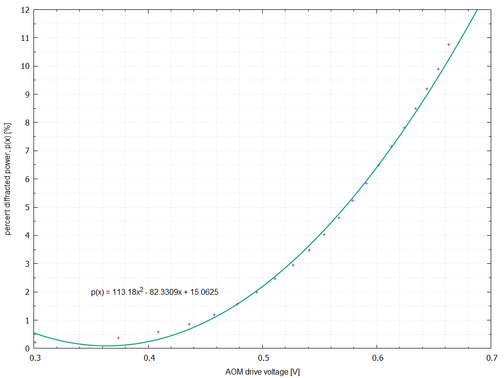
- Measure the beam divergence on the return beam and compare to the beam from the fiber launcher. These should be well matched as the beam is supposed to be retro-reflected from the ETM.
- After optimizing the return beam. Install the Hartmann plate and quantify the spatial distribution and noise in the reconstructed wavefront.


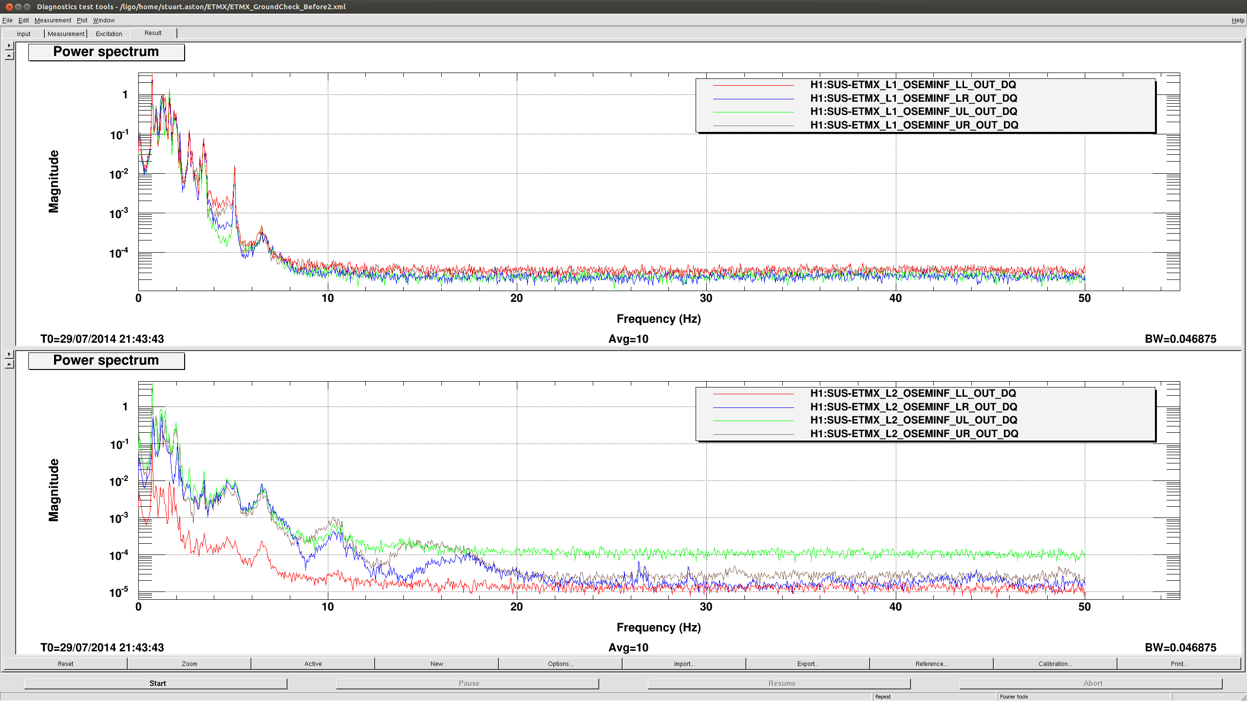
travis.sadecki@LIGO.ORG - 16:23, Tuesday 22 May 2018 (42127)
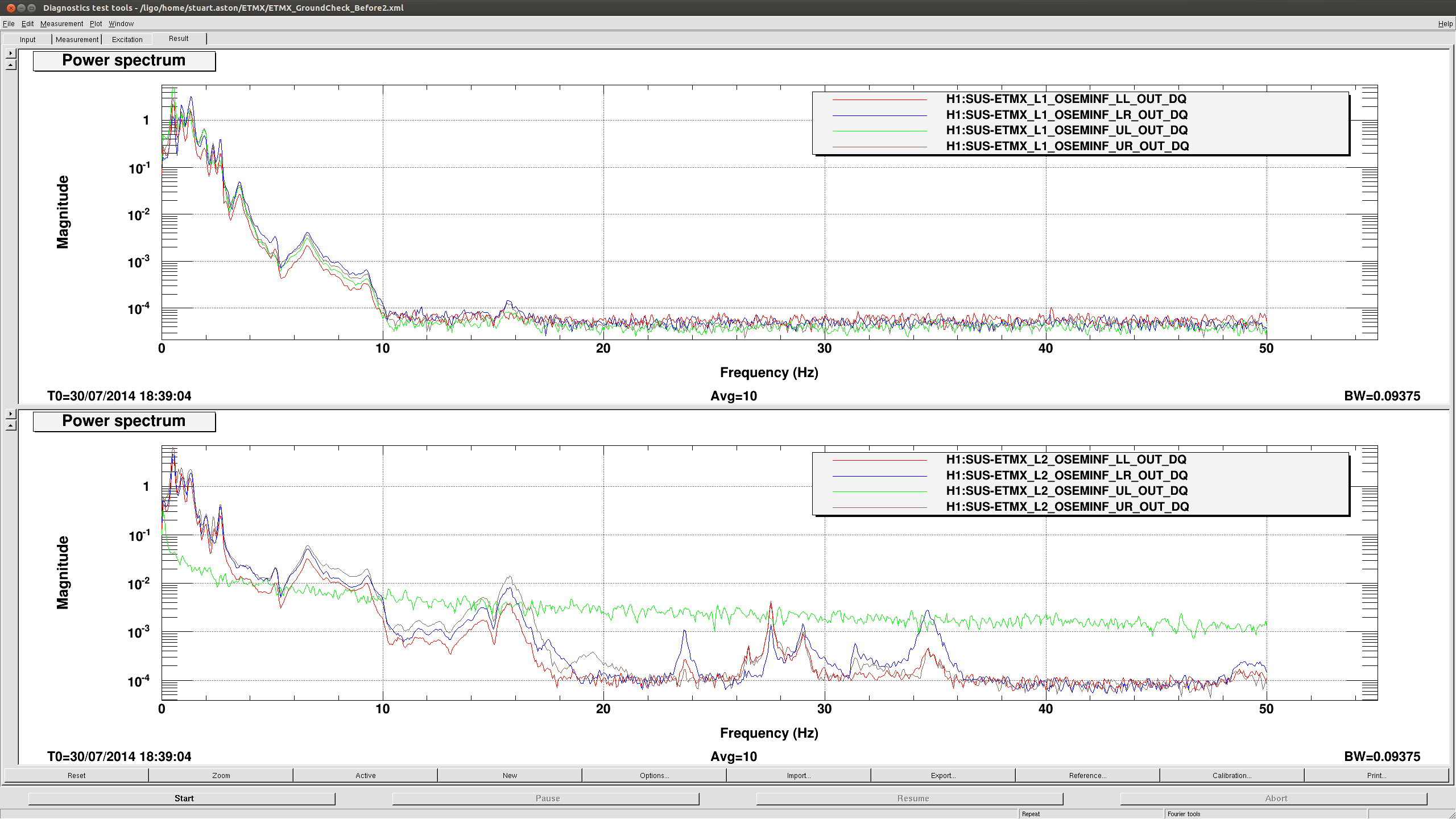
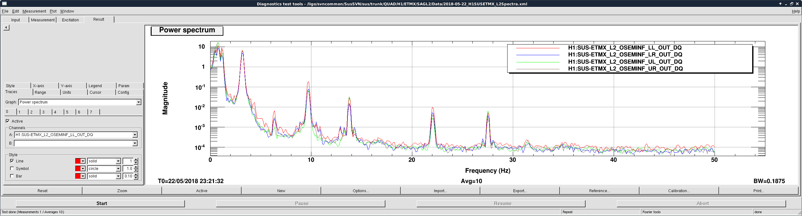
Betsy and I swapped the quadrapuss cable to the L2 (PUM) AOSEMS. This seems to have fixed the noise issue that had been plaguing the UL OSEM for several years. See attached spectra for comparison.
After swapping the cable, we noticed that the 2 lower AOSEMs at the L2 stage (LL and LR) had low OLV values, so we decided to swap these as well. We also took OLV values for UL and UR that were not replaced, but are dying of natural causes.
1.194