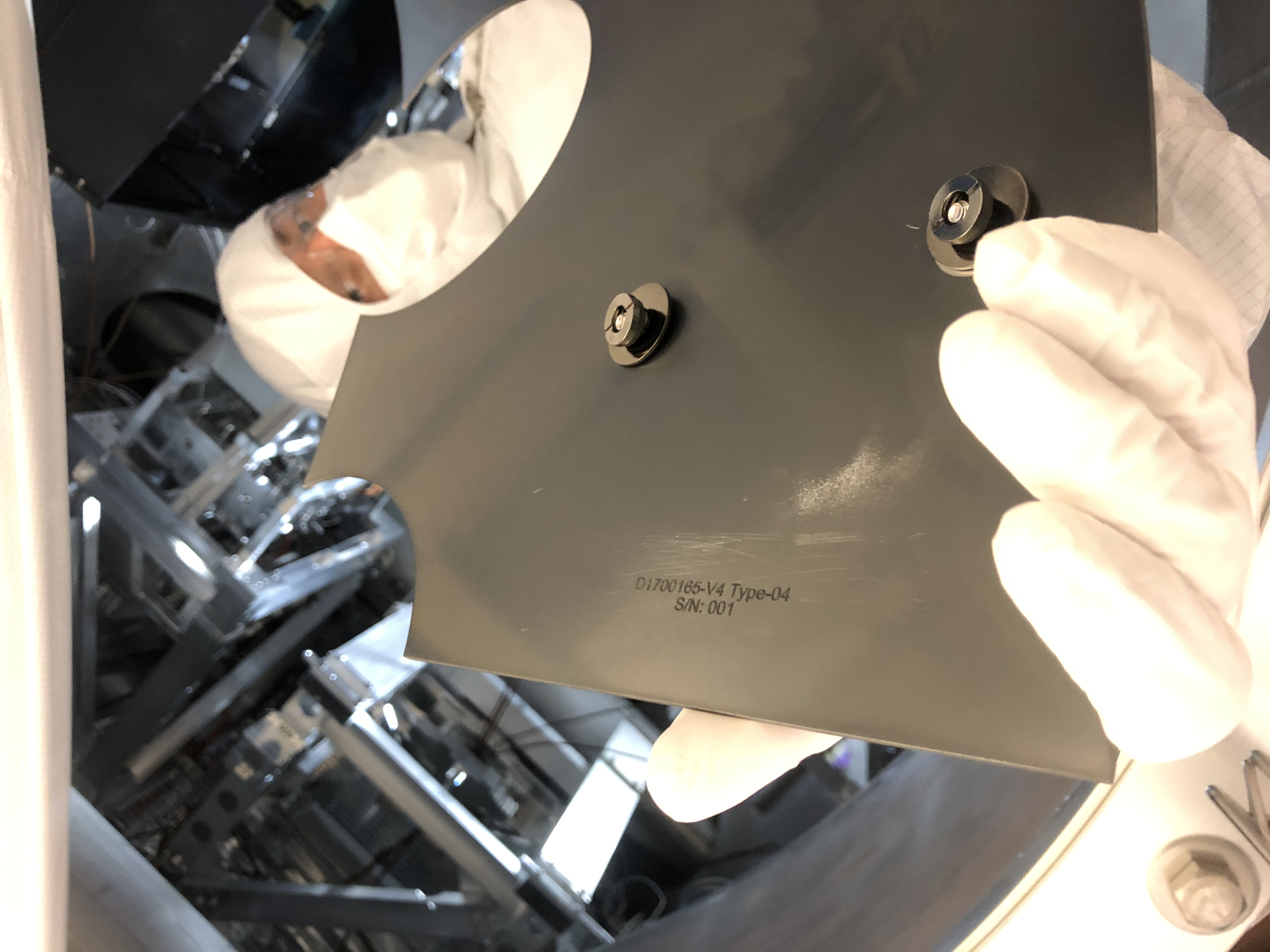
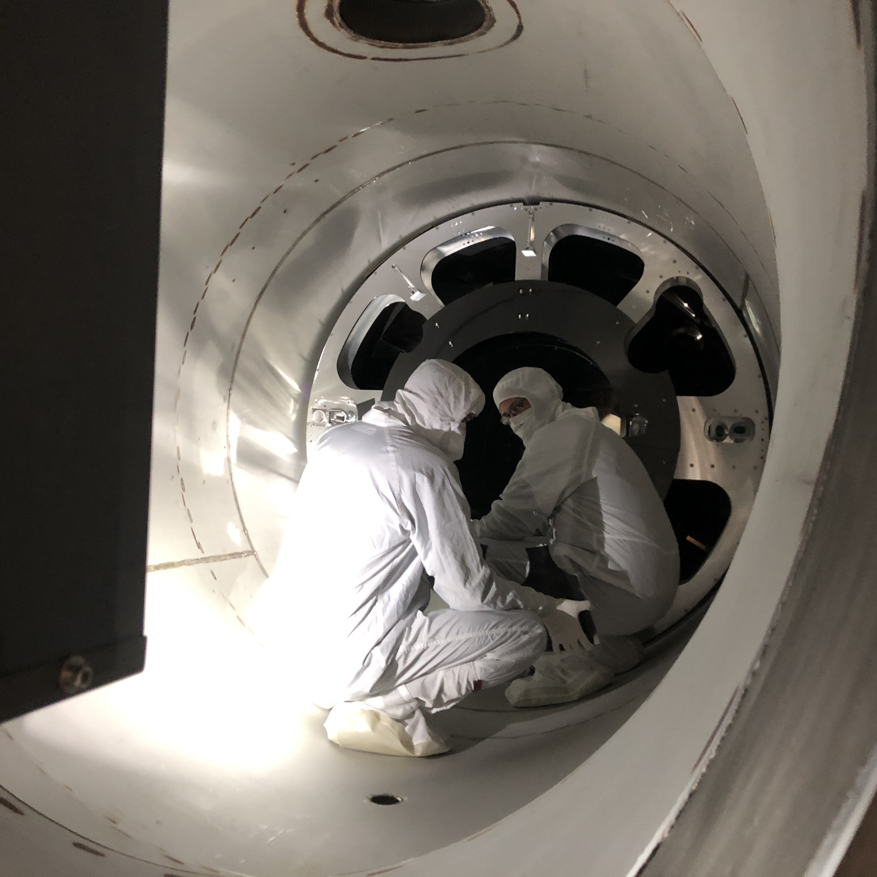
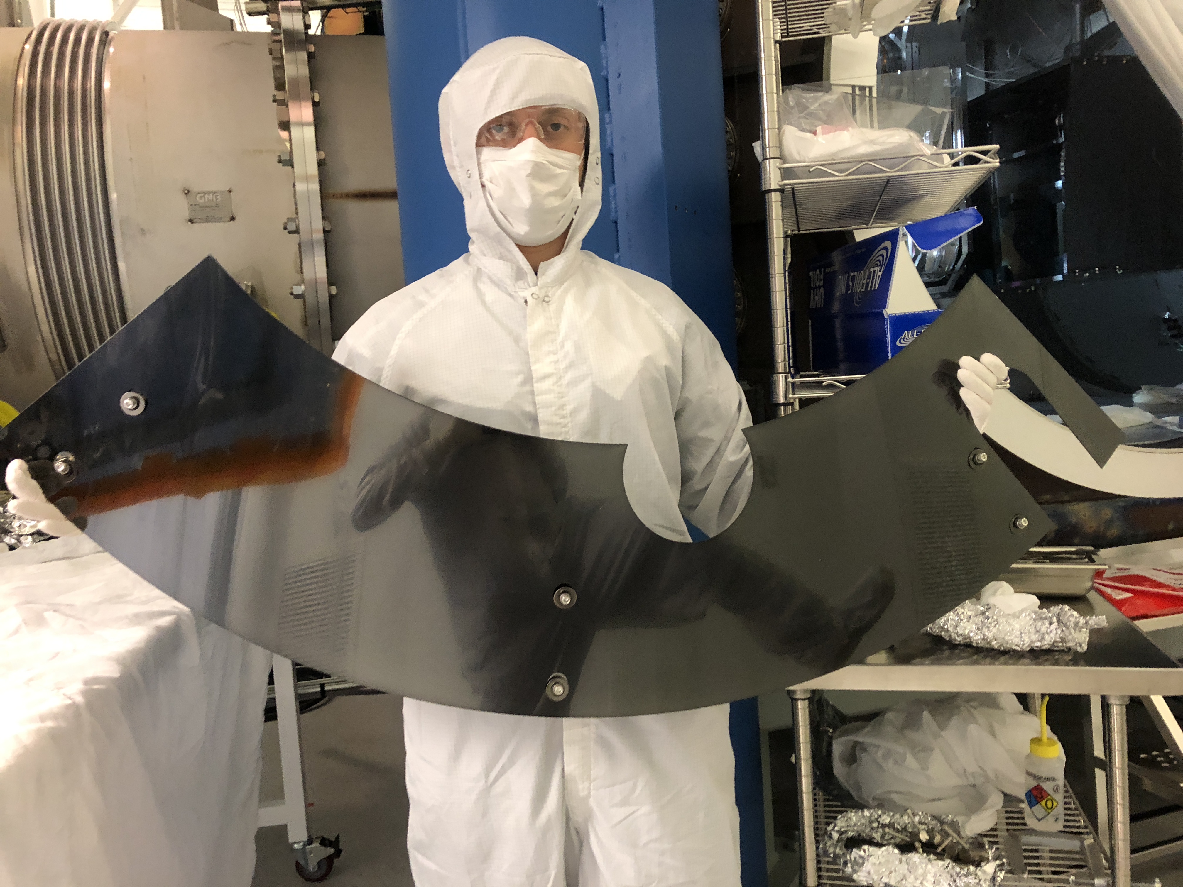
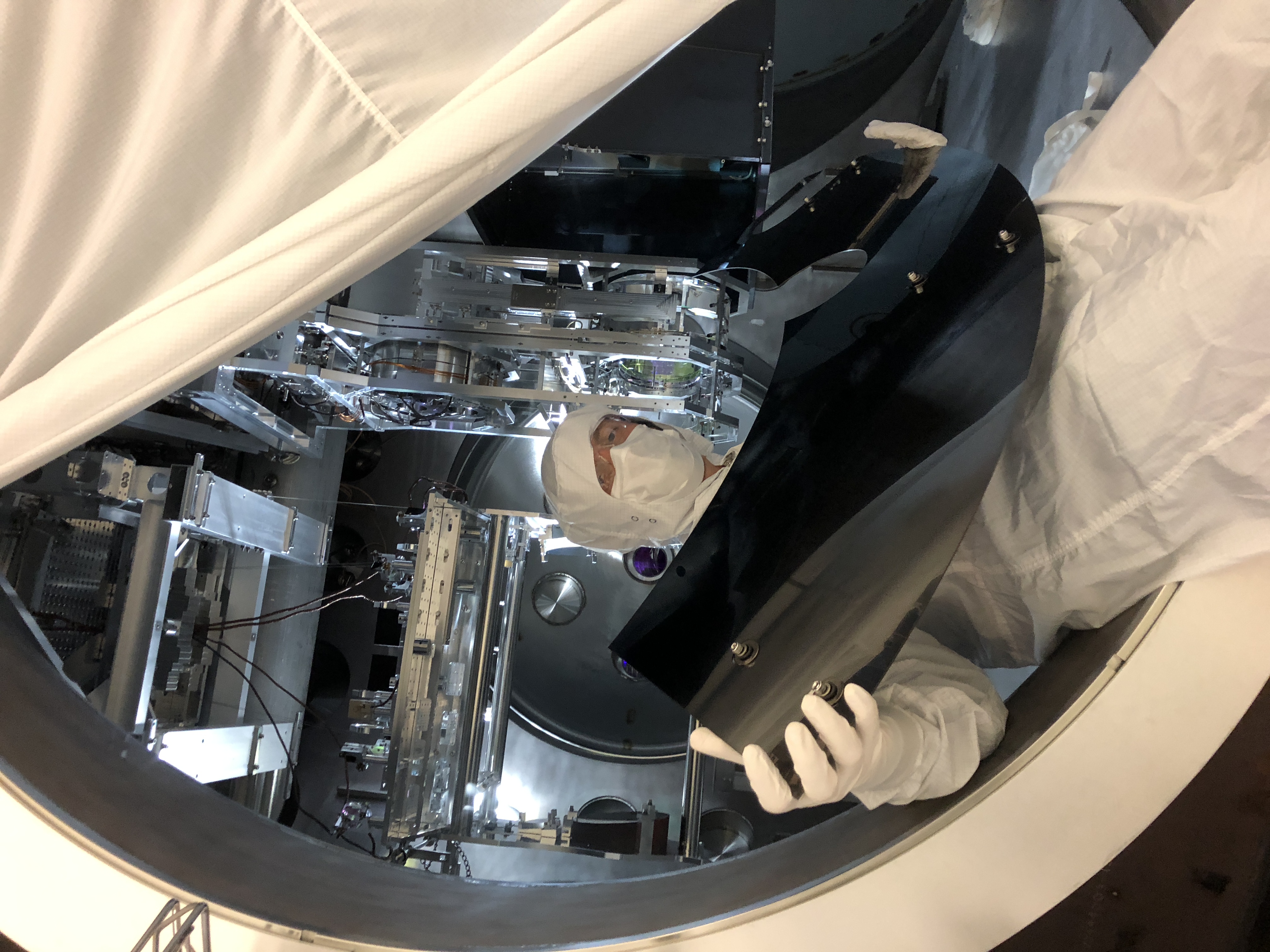
sebastien.biscans@LIGO.ORG - posted 16:10, Friday 18 May 2018 - last comment - 17:48, Friday 18 May 2018(42080)
AMD installation at LHO DONE!
Sebastien, Slawek, Travis
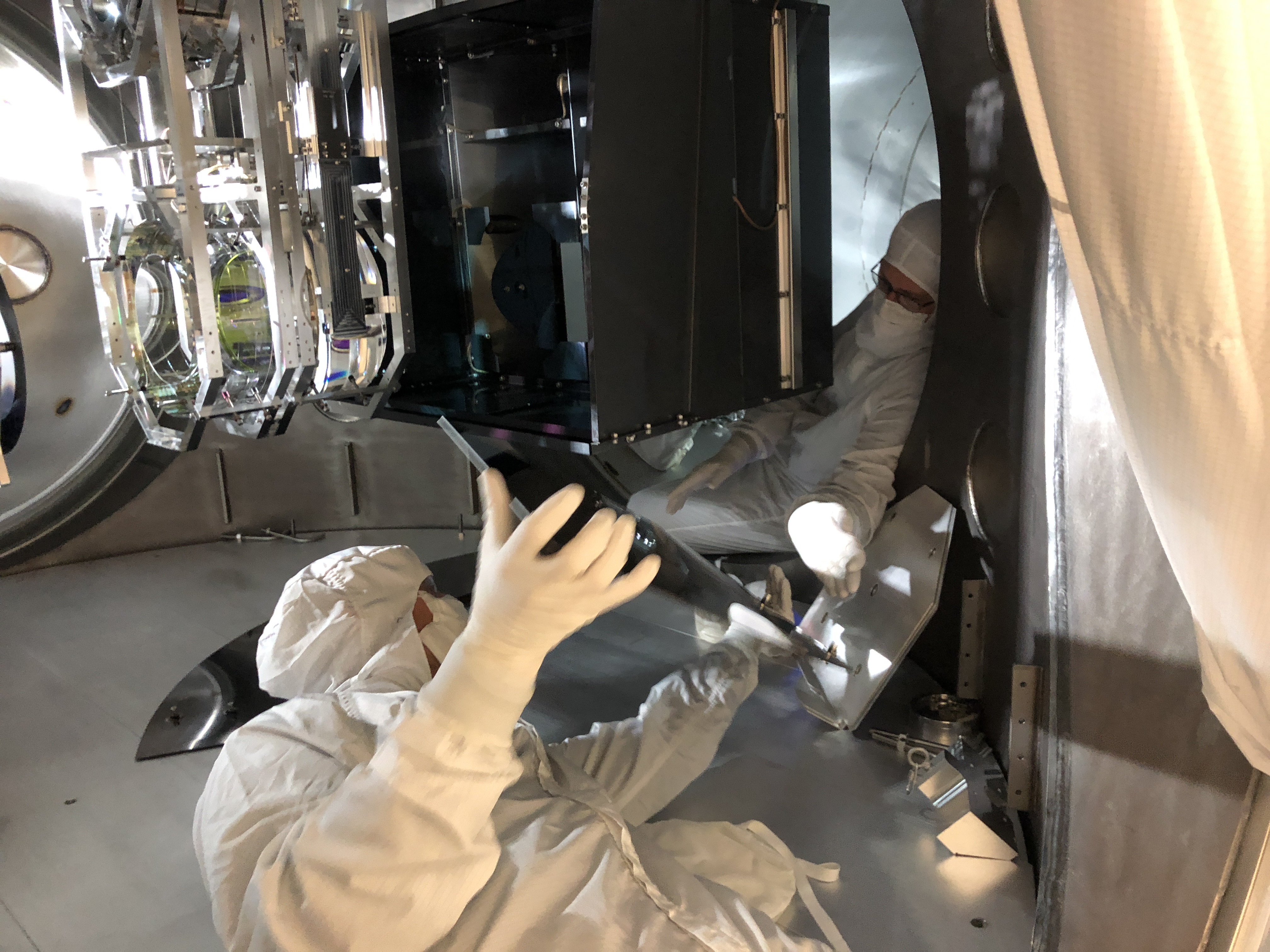
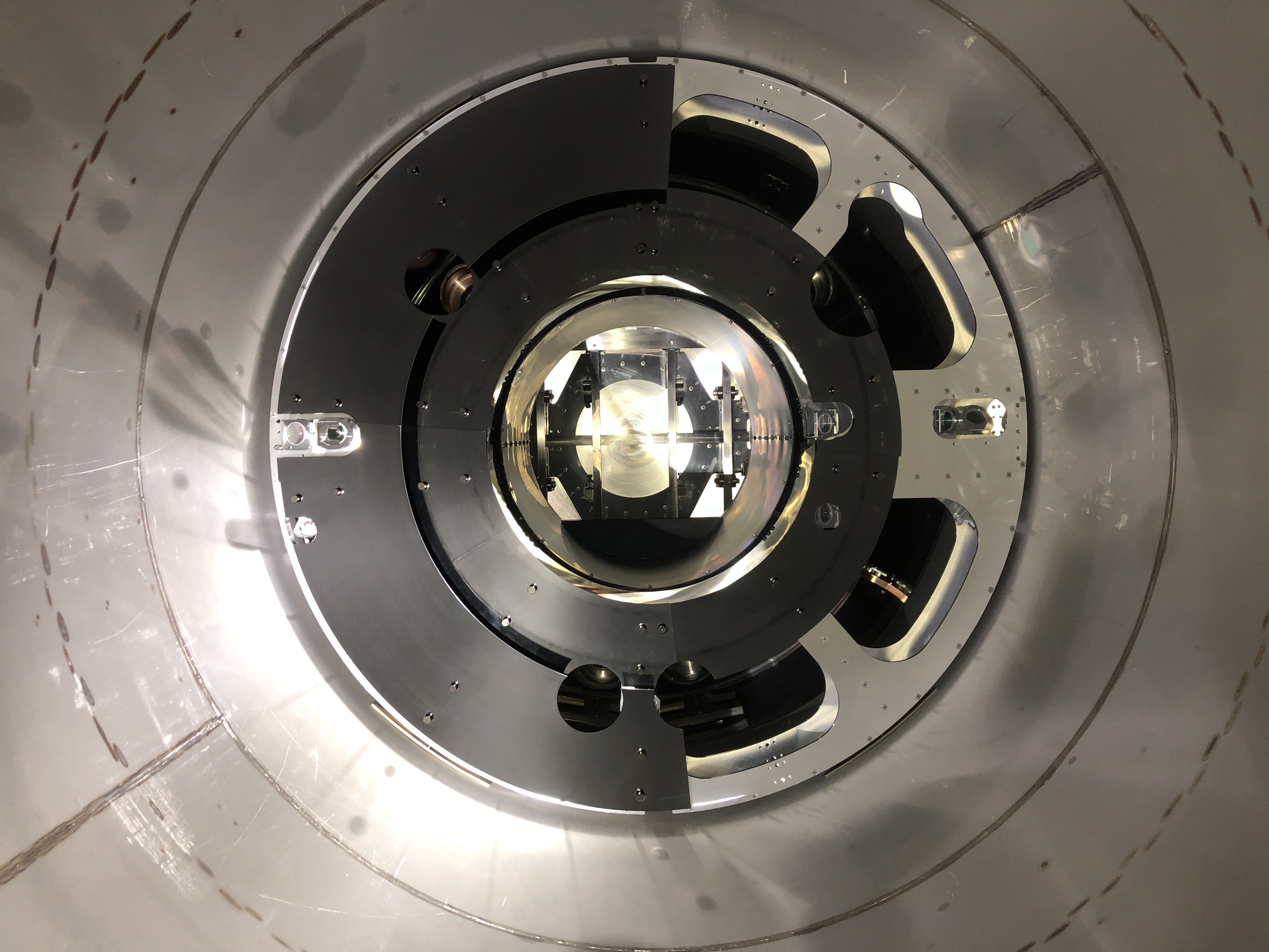
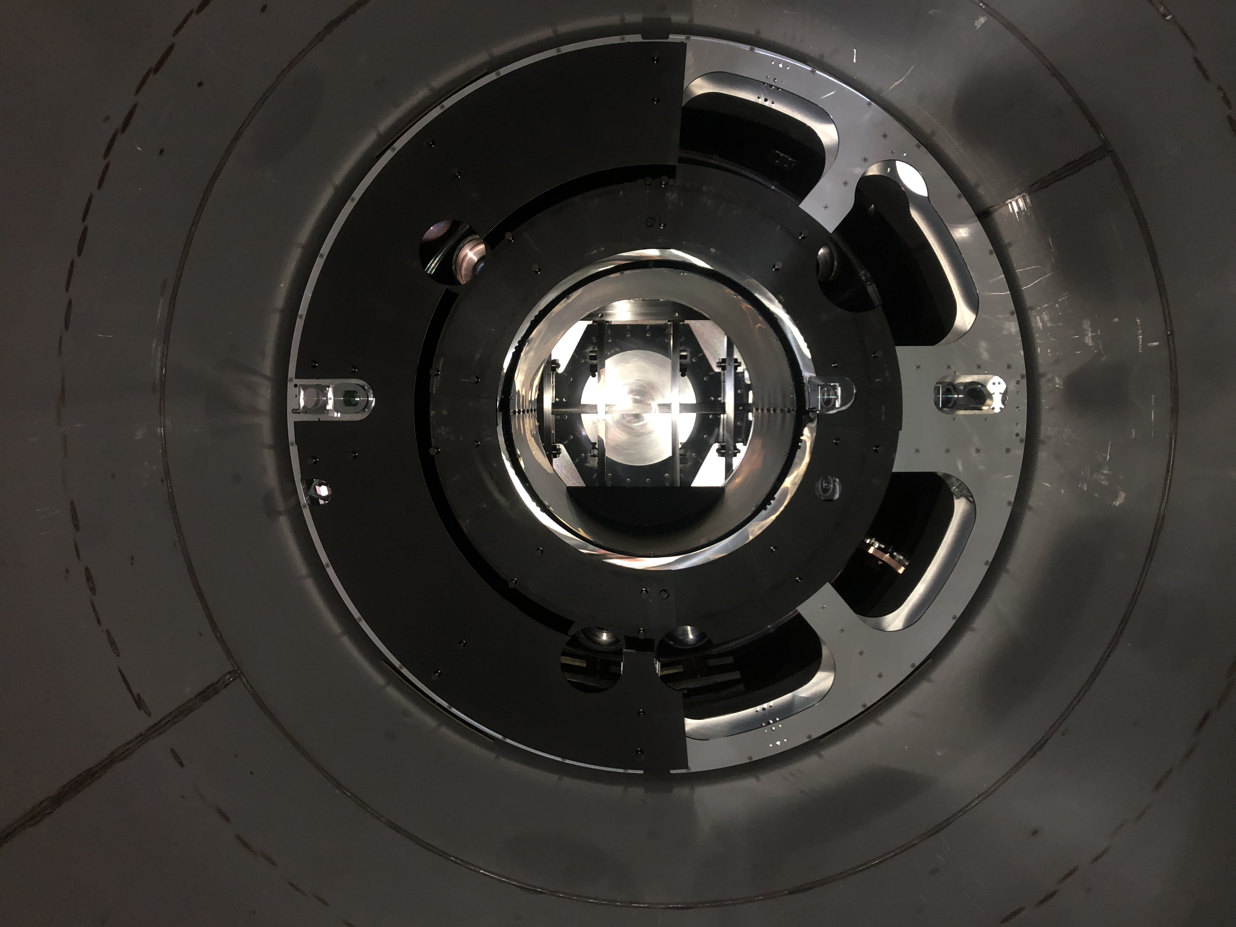
We pulled out the remaining jigs from the ETMX chamber this afternoon. All the AMDs are still in place in their nominal locations, with what looks like homogeneous bond (Slawek will post pictures later). No issue to report.
This was the last chamber: all the test masses are now equipped with 4 AMDs. Big thanks to the team for the warm welcome and the help.
Comments related to this report
Non-image files attached to this comment

ETMx_AMD.pdf
ETMx_AMD_Pos.pdf