Ops Shift Log: 05/17/2018, Day Shift 15:00 – 23:00 (08:00 - 16:00) Time - UTC (PT)
State of H1: Unlocked for upgrades
Intent Bit: Engineering
Support: X
Incoming Operator: X
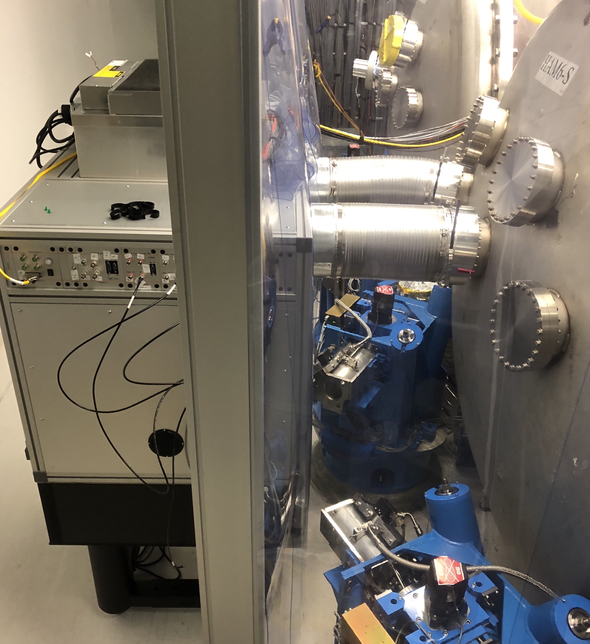
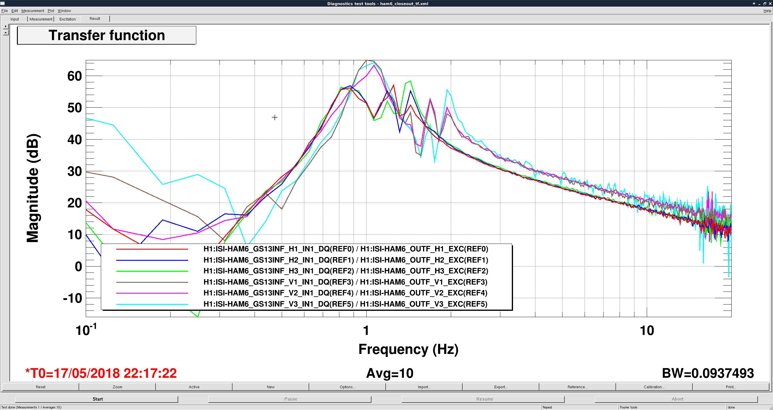
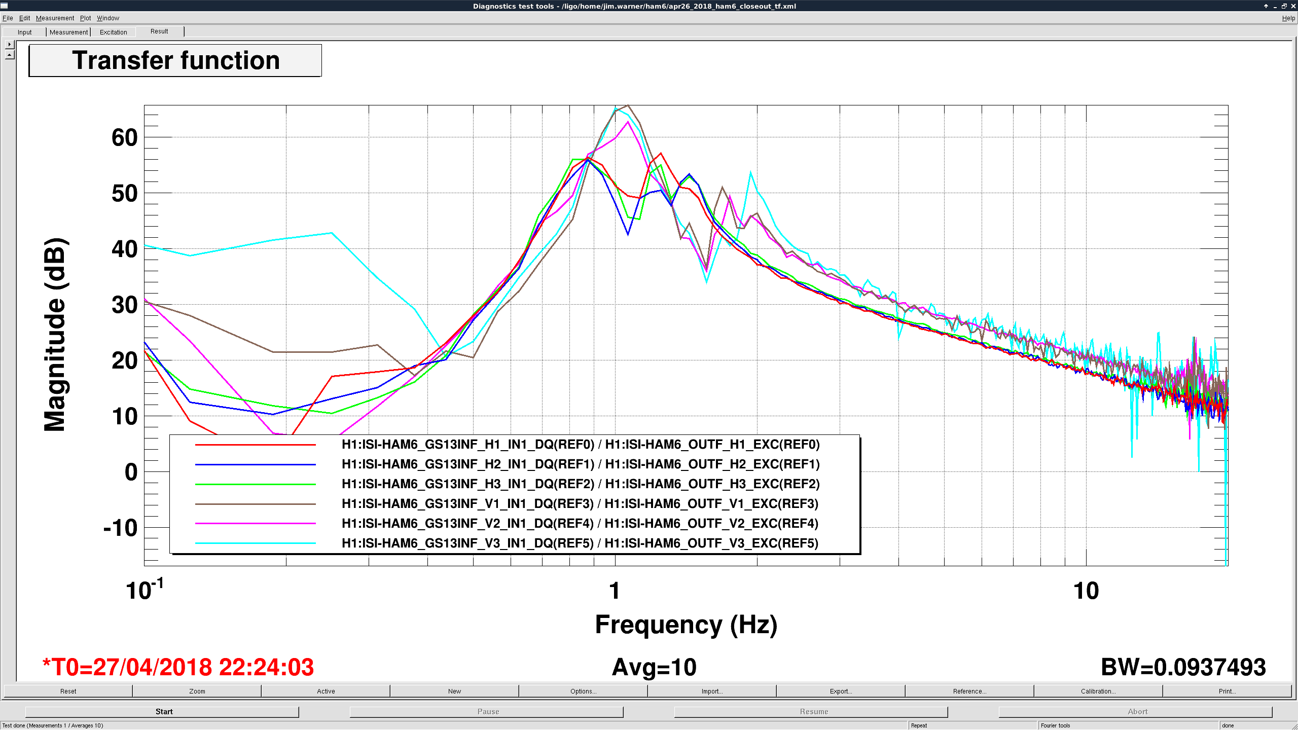
Shift Summary: HAM6 table work, End-X close out, commissioning
Activity Log: Time - UTC (PT)
16:30 (09:30) Take over from Cheryl
16:39 (09:39) Peter – Transition the LVEA to laser hazard
16:56 (09:56) APS on site – Access control system install
17:02 (10:02) Hanford – Testing alarms in 300 area
17:07 (10:07) Daniel S. – Going to Squeezer bay – will turn on laser
17:25 (10:25) School tour of control room
17:25 (10:25) Jenni & Alexie – Going into IOTC6
17:42 (10:42) School tour of control room
17:57 (10:57) Filiberto – Going into the LVEA to move power supply into the CER (WP#7567)
18:11 (11:11) Jenni & Alexie – Out of the LVEA
18:24 (11:24) APS – On site for access controls work
18:25 (11:25) Karen – Cleaning in the H2 room
18:27 (11:27) Marc – Going to the vault
18:43 (11:43) Robert – Going into the PSL Enclosure to mount accelerometers
18:48 (11:48) Richard & Niko – Going into the LVEA
18:53 (11:53) Karen – Out of the H2 building
18:55 (11:55) Richard & Niko – Out of the LVEA
18:55 (11:55) Filiberto – Out of the LVEA
19:04 (12:04) Marc – Back from vault
19:20 (12:20) Daniel S. – Out of the LVEA
19:36 (12:36) Filiberto – Going to the vault
19:41 (12:41) Marc – Going to the vault
19:56 (12:56) Jim – Going to HAM6
20:22 (13:22) Daniel B., - Going to HAM6
20:30 (13:30) Corey – Going to HAM6/Squeezer
20:40 (13:40) School tour of control room
20:45 (13:45) Robert – Out of the PSL enclosure
20:55 (13:55) School tour of control room
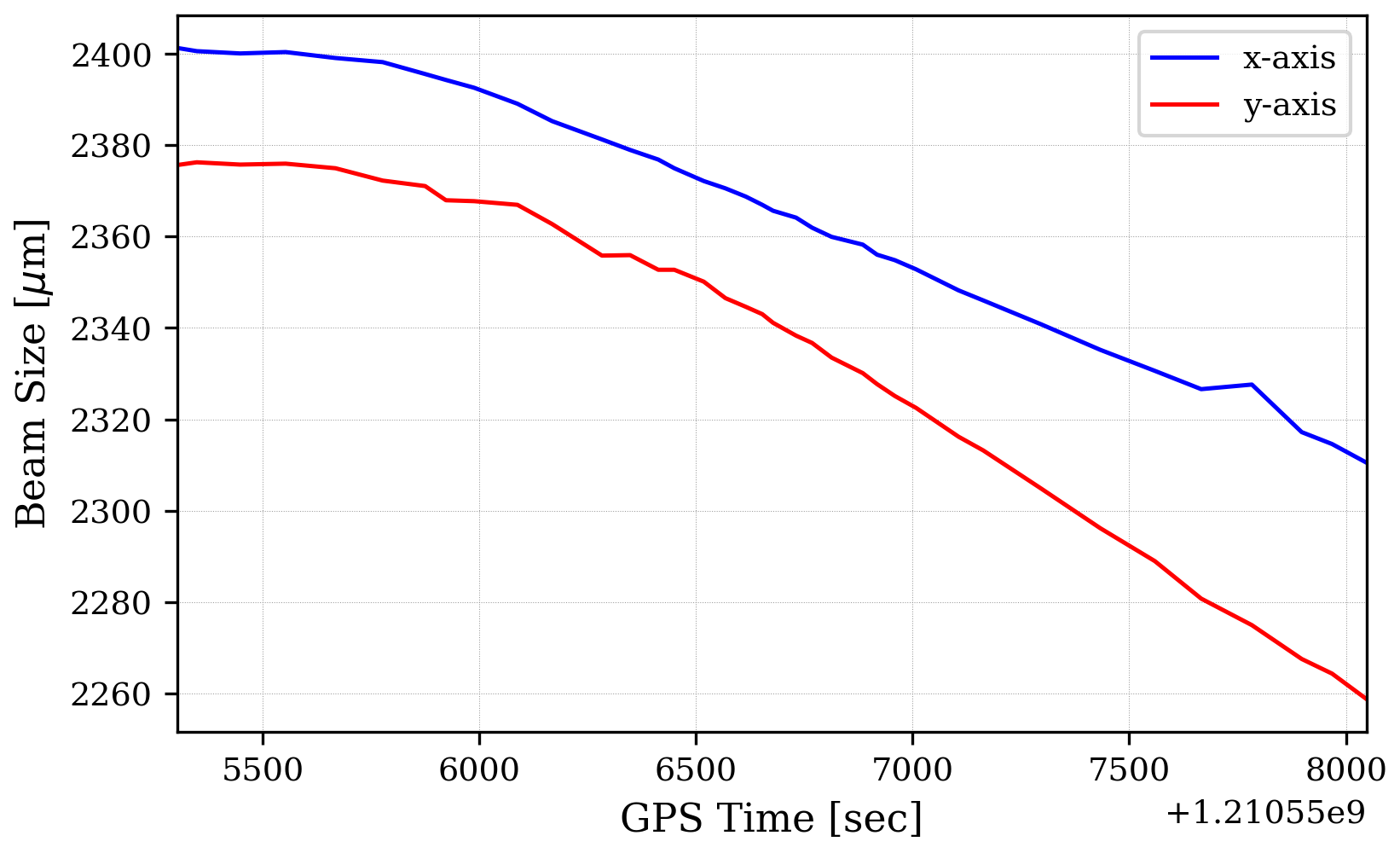
21:05 (14:05) Alexei – Going to HAM6 with beam profiler laptop
21:20 (14:20) Filiberto & Marc – Back from the vault
21:27 (14:27) APS – On site for access control work
21:32 (14:32) Travis & Sebastian – Going to End-X to install AMD
22:14 (15:14) Gerardo – Going to End-X
22:19 (15:19) Corey – Installing light pipes for Squeezer table (WP #7571)
22:25 (15:25) APS – On site for access control system
22:34 (15:34) Gerardo – Back from End-X
21:48 (15:48) Filiberto – Going to HAM6 for ground loop checks
22:48 (15:48) Marc & Peter – Going to the vault
23:00 (16:00) End of shift


Morning Meeting Minutes
Instructions for accessing the backup TeamSpeak server are here: https://wiki.ligo.org/LSC/RemoteParticipation/TeamSpeak
Regular TeamSpeak server usage should be possible again.